llaza SPLENBOX 400 User manual

1
Fecha / Date: 31 Enero 2019 / 31st January 2019
REF. 45098014000
REV. 3
SPLENBOX 400
Manual de Instalación
installation manual

2
0.1–Descripción del producto / Product description
0.2–Leyenda / Icon legend
Usar con sol
Use with sun
No usar con nieve
Don’t use with snow
No usar con lluvia
Don’t use with rain
No usar con granizo
Don’t use with hail
Uso con sol y lluvia
Use with sun and rain
Clasicación por ciclos /
Class by N. of cicles
Manivela
Crank
Motorizado
Motorized
¡Atención! tensión brazos
Danger! Strong arm tension
ART-250
Splendor 300
ART-350
Splendor 400
Onyx
WIN
ART-500
Barra de carga EVO
EVO front prole
B. carga Univers
Univers front prole
0-27 Km/h
28-37 Km/h
+38 Km/h
Información
Informaon
Fabricado en Europa
Made in Europe
Marcado CE
CE standards
Inox
Línea
Width
Salida
Projecon
2 años de garana
2 years of warranty
3 años de garana
3 years of warranty
Eco-friendly
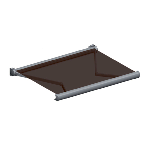
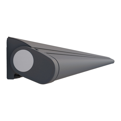
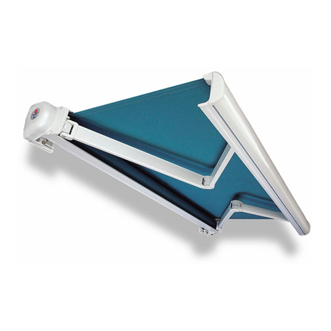
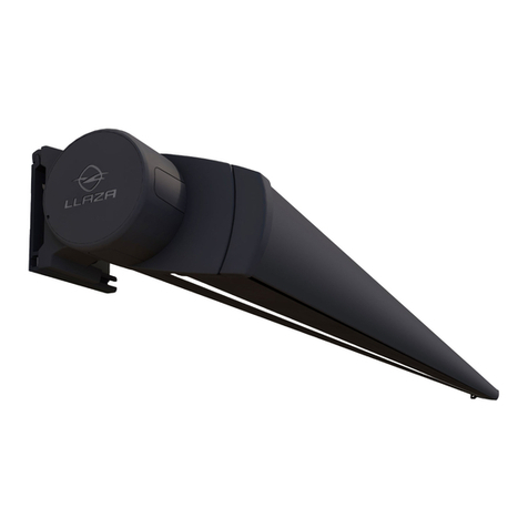
Conjunto Cofre Splenbox 400 con regulación independiente por cremallera
Alineación de los brazos: desde el espárrago externo del soporte.
Inclinación del conjunto: 6-66º a frontal y 18º-66º a techo.
Permite dimensiones de 6,00 m. de línea sin soportes intermedios.
Consigue una salida y capacidad de enrolle de 4,00 m. con tubo de Ø80mm.
Diseñado completamente metálico, por lo que ofrece un aspecto impecable de alto valor estéco y gran calidad.
Splenbox 400 cassee awning with adjustment of slope using an independent rack system.
Alignment of the arms: from the external threaded stud of the support.
Slope: 6-66º (wall mounng) and 18º-66º (ceiling mounng).
This model allows a width of 6.00 m. with no need of intermediate supports.
Its projecon and roll up capacity is 4.00 m. using a Ø80mm tube.
It is designed enrely in metal, giving it an impeccable appearance of high aesthec value and top quality.
SPLENBOX 400

3
2.1.- Despiece del producto / Product parts
2.2.–Nomenclatura / Nomenclature
SPLENBOX 400
SPLENBOX 400
ESTE CONJUNTO TAMBIÉN SE PUEDE CONFIGURAR CON BRAZOS ONYX
THIS MODEL CAN ALSO BE ASSEMBLED WITH ONYX ARMS

4
SPLENBOX 400
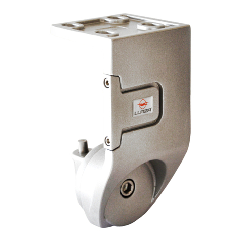
Placa de sustentación
Frontal / Techo
Fixing plate
Wall / Ceiling
1.1..–Secciones acotadas / Section dimensions
FIJACIÓN FRONTAL / WALL MOUNTING FIJACIÓN A TECHO / CEILING MOUNTING

5
4.1 –Información de maniobras y clase / Information about cycles and class
Los brazos llevan una banda protectora de colores para su idencación:
VERDE: Visto desde fuera, lado derecho
ROJA: Visto desde fuera, lado izquierdo
3.1 –Clasificación según norma Europea / Classification according to European standards: EN 13.561:2015
The arms have a protecve band for correct idencaon:
GREEN: Right hand side viewed from outside
RED: Le hand side viewed from outside
SPLENBOX 400
2.1- Tablas de selección motor / Selecction motor table
NUNCA EXTRAER LAS BANDAS DE SEGURIDAD PARA LA TENSIÓN HASTA HABER SUJETADO EL BRAZO AL PERFIL DE CARGA.
NEVER EXTRACT THE SAFETY TENSION BANDS UNTIL THE ARM HAS BEEN FIXED TO THE FRONT PROFILE.
Salida brazo / Arm projecon (m) Línea / Width Clase / Class
4,00 6,00 C.1
Tubo enrolle Ø70 /
Ø70 Rolling tube
Linea / Width (m)
2,00 2,50 3,00 3,50 4,00 4,50 5,00 5,50 6,00
Salida /
Projecon
(m)
1,50 30 30 30 30 30 30 30 30 30
2,00 30 30 30 30 30 30 30 30
2,50 35 35 35 35 35 35 35
3,00 35 35 40 40 40 40
3,50 40 40 40 40 50
4,00 50 50 50 50
Tubo enrolle Ø80 /
Ø80 Rolling tube
Linea / Width (m)
2,00 2,50 3,00 3,50 4,00 4,50 5,00 5,50 6,00
Salida /
Projecon
(m)
1,50 30 30 30 30 30 30 30 30 30
2,00 30 35 35 35 35 35 35 35
2,50 40 40 40 40 40 40 40
3,00 50 50 50 50 50 50
3,50 50 50 50 50 50
4,00 50 50 50 50

6
SPLENBOX 400
5.1- Herramientas y accesorios recomendados para la instalación /
Recommended tools and accessories for installation procedure
6.1- Línea / Width
La distancia entre la parte exterior de las placas, si ulizamos laterales embellecedores, será L-40 mm., siendo L= línea total
The distance between the exterior part of the wall plates, when using the side cover kit, should be: L-40 mm, when L=total width
7.1.- Instrucciones de instalación —Installation instructions
S
Línea total accionamiento motor / Total width for motor operaon (L)
L-40

7
SPLENBOX 400
8.1.- Instrucciones de instalación —Installation instructions
Fijación del conjunto sobre los soportes pared / Fixing the cassee support to the wall bracket.
Para la realización de un cambio de inclinación en el conjunto / To change the cassee slope proceed as
indicated in the drawing.
Al nalizar la regulación apretar de nuevo los tres
tornillos de jación/
Fasten the three screws once the adjustment is
nished.

8
SPLENBOX 400
8.1.–Instrucciones de fabricación / Assembly instructions
Para la realización de un cambio de paralelismo en el conjunto /
To modify the alignment of the arms, proceed as follows.
Regulación paralelismo /
Parallelism regulaon
Fijación paralelismo /
Parallelism xing
Distancia de posicionamiento de los terminales desde el extremo del corte del perl frontal al extremo del terminal /
Posioning distance for the front rail connectors measured from the end of the front prole to the outer end of the
front rail connector.
8.2.–Instrucciones de fabricación / Assembly instructions
IMPORTANTE: Los tornillos del terminal siempre hacia la posición de
exterior (según dibujo)/
VERY IMPORTANT: The screws for the front rail connectors must be
oriented towards the outside (as shown in the drawing).

9
SPLENBOX 400
8.3.–Instrucciones de fabricación / Assembly instructions
8.4.–Instrucciones de fabricación / Assembly instructions
Para la colocación de las regletas y tapas laterales /
Introducon of the joining insert and plasc caps
Fijación de la tapa lateral al conjunto soporte / Mounng the side aluminium cap to the cassee structure.
IMPORTANTE: Vericar que en cada lado del perl de carga estén los panes
IMPORTANT: Do not forget that a plasc runner has to be introduced at each side of the prole
Accionamiento Motor /
Motor operaon
Accionamiento Motor /
Motor operaon

10
BASIC NOTES ON ASSEMBLY AND INSTALLATION:
Assembly and installaon should be done by trained personnel.
IMPORTANT SAFETY CONSIDERATIONS: For proper installaon of the awning, the instrucons for assem-
bly and installaon must be carefully followed step by step. Keep plasc bags or any other mounng
pieces out of children’s reach.
Do not alter the design or the conguraon of the system, nor modify the installaon method without
consulng the manufacturer or an authorised representave.
If the awning is motorised and there is a switch, this should be placed so that the user does not interfere
with the movement of the awning, and at a height of less than 1.3 metres when possible.
If the awning is manually operated, it should be accessible at a height of 1.8 metres.
If the awning is to be installed in windy areas where there are frequent blackouts, manual operaon or
the use of a back-up generator is recommended.
When motorised units are inspected or repaired, always disconnect them from the power supply.
BASIC PRECAUTIONS FOR SAFE HANDLING OF THE AWNING:
The awning must be rolled away:
In the event of ice, if operaon is parcularly dicult and in the absence of safety measures, stop the
operaon unl more favorable condions prevail
During opening and closing, make sure there is no obstacle which could get in the way. NEVER FORCE
THE AWNING!. If the awning does not move at all when you try to operate it, call a professional installer.
In the case of motorized awnings, it should be borne in mind that the motor features a thermal safety
device to avoid overheang and breakdowns. This device is acvated when the operang switches are
pressed insistently.
Do not submit the installaon to addional loads or stresses not covered by the manufacturer’s
conguraon. Do not interfere with the system’s xing components.
Examine the installaon if it has been subjected to adverse weather condions, and if any repairs are
needed do not use it. In such cases, a professional installer should be called.
Keep the installaon clean and in good condion. A yearly maintenance check by an authorized
professional installer is recommended.
IMPORTANT SAFETY INSTRUCTIONS. The system has powerful springs inside it. In the event of
poor installaon, these may cause the awning to open sharply. If any irregularies are observed dur-
ing opening and/or closing, call a professional installer. To avoid possible damage, do not allow
children to play with the awning.
SPLENBOX 400

11
PRECAUCIONES BÁSICAS PARA UN MANEJO SEGURO DEL TOLDO:
Se debe recoger el toldo ante situaciones meteorológicas adversas como:
En caso de hielo, si la maniobra es parcularmente dicil, y en ausencia de disposivos de seguridad, de-
tener la maniobra hasta que se restablezcan unas condiciones más favorables.
Durante las maniobras de apertura o cierre, vericar que no exista ningún obstáculo que cause algún im-
pedimento. ¡NO FORZAR NUNCA EL TOLDO!. Si al intentar maniobrar el toldo, éste no efectúa movimiento
alguno, será necesario avisar a un profesional instalador
En caso de que el toldo esté motorizado, debe tenerse en cuenta que el motor incorpora un dispo-
sivo de seguridad térmica para evitar sobrecalentamientos y averías. Este disposivo se pone en marcha
cuando se pulsan insistentemente los inversores de accionamiento.
No someter la instalación a esfuerzos o cargas adicionales e independientes a la conguración dada por
el fabricante. No actuar sobre los elementos de jación del sistema.
Examinar la instalación si ha sido someda a condiciones climácas adversas, y no ulizarla si es nece-
saria alguna reparación. En tal caso, será necesario avisar a un profesional instalador.
Mantener la instalación limpia y en buenas condiciones, y se recomienda una revisión de man-
tenimiento anual realizada por un instalador profesional autorizado.
INSTRUCCIONES IMPORTANTES PARA LA SEGURIDAD. El sistema dispone de potentes resortes en el
interior que en caso de una instalación en malas condiciones, pueden causar una apertura brusca
del toldo. Si se observa alguna anomalía durante las maniobras de apertura y/o cierre, avisar a un
profesional instalador. No permir a los niños jugar con el toldo para evitarles posibles daños.
SPLENBOX 400
CONSIDERACIONES BÁSICAS PARA EL MONTAJE Y LA INSTALACIÓN:
El montaje y la instalación de este producto debe realizarlo personal cualicado.
INSTRUCCIONES IMPORTANTES PARA LA SEGURIDAD. Atender a las advertencias de seguridad indica-
das junto al producto o en las instrucciones de montaje. Las bolsas de plásco y otros elementos de
montaje no son ningún juguete y deben quedar fuera del alcance de niños o personal ajeno al mon-
taje.
No modicar el diseño ni la conguración del sistema ni las indicaciones dadas para la jación del toldo
sin consultar al fabricante o su representante autorizado.
En caso de toldo motorizado + interruptor, éste debe situarse a una altura del suelo inferior a 1,30m. .
Emplazar evitando la interferencia accidental del usuario.
En caso de accionamiento manual del toldo, éste debe ser accesible desde una altura inferior a 1,80 m.
En caso de instalaciones en zonas de viento y con frecuentes fallos del suministro eléctrico, se reco-
mienda que el accionamiento del toldo sea manual o con una generador eléctrico alternavo.
Durante las inspecciones de mantenimiento o reparaciones en una instalación motorizada, el sistema
debe estar desconectado del sistema eléctrico.

12
LLAZA WORLD, S.A.
Tramuntana, 1. Pol.Ind. Roques Roges
43460 ALCOVER
Tel. +34 990 600 / Fax +34 977 990610
e-mail: [email protected] / E[email protected]
Other manuals for SPLENBOX 400
1
Other llaza Accessories manuals

llaza
llaza STORBOX 300 User manual

llaza
llaza SPLENBOX 400 User manual

llaza
llaza MONOBOX-400 User manual

llaza
llaza STORBOX 250 User manual

llaza
llaza SPLENBOX 300 User manual

llaza
llaza SPLENBOX 300 User manual

llaza
llaza MOONBOX 400 User manual

llaza
llaza COMPLET-PRO 350 User manual

llaza
llaza STORBOX 300 User manual
Popular Accessories manuals by other brands

Kerbl
Kerbl EP535 User information

weinor
weinor Semina Maintenance instructions and directions for use

VWR International
VWR International 3074 operating instructions

ring
ring Doorbell Pro 2 user guide

Aventics
Aventics SM6-AL operating instructions

Keysight Technologies
Keysight Technologies U8480 Series Service guide