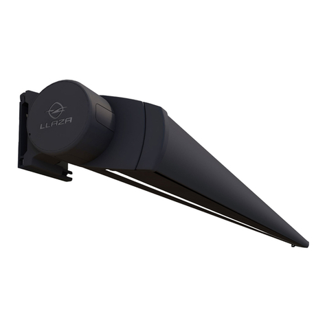
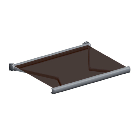
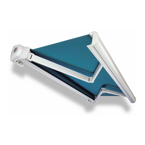
llaza MONOBOX-400 User manual

Page - Copyright Llaza, S.A. - May 2011
Technical Manual
MONOBOX-400

Page 2 - Copyright Llaza, S.A. - May 2011
Contents
Descriptive specifications 3-5
Cutting, selection, and classification tables 6-7
Annotated cross-sectional diagrams 8
Assembly instructions 9-16
Installation instructions 17-19
MONOBOX-400

Page 3 - Copyright Llaza, S.A. - May 2011
Descriptive specifications
1. GENERAL CHARACTERISTICS
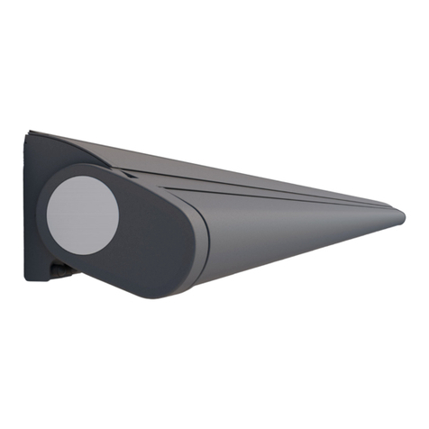
The MONOBOX-400 awning brings together a series of innovative characteristics that make it stand out
from other conventional systems.
The articulated arm system, in conjunction with its other clearly unique characteristics, adds value to result
in a top-of-the-line end product that responds to the needs of today’s professionals in the architecture and
decorating sectors.
Because it can be fully integrated into the appearance of the façade, this sun protection system meets all
the requirements so often cited by professionals in these fields and can be a part of any architectural pro-
ject from the earliest stages of development.
To all of this we can also add the built-in advantages that the Monobloc system provides in terms of instal-
lation, as well as the ease of adjusting the system’s inclination by means of the patented option known as
MATIC, which has been developed by our technical department.
2. DESCRIPTION OF THE SYSTEM
The MONOBOX-400 awning is a system based on:
■ Support of the load-bearing component with Monobloc technology
This system allows the articulated extension arms (with internal elongation mechanisms) as well as the
components that make up the system generating the rotational movement to be anchored to a square bar.
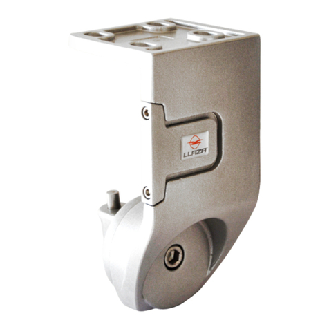
This bar is in turn attached to the front of a wall or below a ceiling using specific anchoring brackets, which
vary in terms of possible dimensions and positions.
The system ensures that the awning is better attached to the surface and is easier to install, since the prod-
uct can arrive at the installation site from the production centre almost fully assembled. This considerably
reduces the amount of time dedicated to installation at the final location.
■ Awning adjustment using the MATIC system
This system increases the range of possibilities for inclination, without requiring excessively large support
brackets.
■ Protection of the fabric component
The area into which the textile element is rolled up is surrounded by an aluminium profile, which is a feature
known as ‘texpro’. This means that when the system is retracted, the fabric is protected from harm from
harsh external elements.
■ Possibility of coupled awning installation
Another advantage of this system is that two awnings can be installed together to cover longer spans. A
cover kit for the gap between the fabrics allows both awnings to be controlled as a single unit.
MONOBOX-400

Page 4 - Copyright Llaza, S.A. - May 2011
As with any sun protection system, this product also seeks to achieve the greatest suitability in terms of two
intrinsic necessities:
■ Dimensions
■ Exposure to the elements (sun, wind, rain)
To address these factors, the materials chosen in the manufacture of this product have taken on vital im-
portance.
3. DESCRIPTION OF THE PARTS THAT MAKE UP THE MONOBOX-400
The square bar that suspends the system is made of extruded aluminium and can allow for projections of 3
metres or even more by placing a 35x35x2 steel pipe inside the bar. The system is suspended on extruded
aluminium brackets, with proven aerodynamic designs to offer unmatched strength and durability.
The rolling tube is anchored to two side brackets that form the ends of the upper cassette, where the fabric
is protected against potentially damaging weather conditions. Both brackets are attached by means of an
interior clamp that prevents the need to drill through the square bar, and to which the aluminium side covers
are also attached. This gives the assembly a novel and modern aesthetic look.
The rotational motion applied to the rolling tube when extending or retracting the fabric is activated by
means of a gearbox with a 1:5 ratio, which if required is accompanied by a tubular compensation spring.
The awning is then operated by either a manual crank or an electric motor positioned inside one end of the
rolling tube.
At the other end (and at the central support as well if the option to divide the width into two awnings has
been chosen), stainless steel ball bearings provide technically calculated support to ensure that the system
operates smoothly and perfectly.
The front profile that serves as a guiding element for opening and closing the system has been designed
with carefully calculated dimensions to be used with extended widths and to improve the aesthetics of the
system even further.
When the awning is extended, it is supported on a structure consisting of the articulated SPLENDOR-type
arms and the corresponding drop bar profile. This model of arm features bearings in the joint, as well as an
internal tensioning system inside the profiles that uses an elongation mechanism, with transmission of the
longitudinal difference by means of a patented flexible tape system. This ensures that the product performs
well above the applicable European EN 13561 standard.
Acrylic or high-tech fabric offers superior sun protection, and is ex-
tended and retracted by rolling onto a steel or aluminium tube. The
MATIC system that attaches the articulated arms to the bar, and
which is made of aluminium, stainless steel, and special bolts, fea-
tures a piston-type action inside, which prevents variability in the incli-
nation of the arm when the awning is fully extended. When retracted,
the cam system returns the arm to a position with 0° inclination. This
allows the movement of the front or drop bar profile with the texpro
system (both made of extruded aluminium) to always occur at this an-
gle.
MONOBOX-400
Page 5 - Copyright Llaza, S.A. - May 2011
Descriptive specifications
With proper use and under suitable conditions, SPLENDOR arms will exceed 60,000 operational cycles.
Also, the appropriate angular calculations for their components prevent them from rubbing against the fab-
ric during the entire extension-retraction process.
An installation with two arms can reach a maximum of up to five metres in width and 3.5 metres of projec-
tion. The Monobloc mounting system allows another identical structure to be added in parallel, both operat-
ed as a single system (see assembly instructions).
4. FINAL CONSIDERATIONS
■ Our manufacturing processes and corresponding management controls have allowed us to be granted
ISO 9001 certification for design and manufacturing.
■ Our compliance with the requirements of the European EN 13561 standard allows us to issue the State-
ment of Conformity for the CE marking.
■ The recommendations found in the TUV standards for strength and safety are rigorously followed.
■ Application of the conditions required by EAA/Qualicoat standards allow us to offer a 3-year guarantee on
lacquer finishes.
5. COMPONENT SPECIFICATIONS
GEOMETRIC PROPERTIES
Geometry Section (mm2) Mt (cm4)
Structure
Structural profile 40x40x3 444 Ixx = 10.19 Iyy = 10.19
Wall support - 3361 Ixx = 438.8 Iyy = 277.7
Ceiling support - 7122 Ixx = 5403 Iyy = 898
Cassette profile - 805 Ixx = 79 Iyy = 255.9
Weather cover - 687 Ixx = 4.6 Iyy = 164.9
Front drop bar - 1253 Ixx = 429.6 Iyy = 39.58
SPLENDOR model arms
Structural components - - -
Front aluminium profile - 319 Ixx = 17.53 Iyy = 39.58
Rear aluminium profile - 379 Ixx = 22.90 Iyy = 77.88
TECHNICAL CHARACTERISTICS
Structure Process Desig. Material ABCD
Components Pressure moulding Aluminium 180 90 2,5 55
Structural profile Extrusion Aluminium 175 130 6-
Wall support Extrusion Aluminium 160 110 5-
Ceiling support Extrusion Aluminium 260 215 6-
Cassette profile Extrusion Aluminium 175 130 6-
Weather cover Extrusion Aluminium 175 130 6
Front drop bar Extrusion Aluminium 175 130 6
Extrusion comp. Extrusion Aluminium 160 110 5
SPLENDOR model arms
Components Pressure moulding Aluminium 180 90 2,5 55
Front alum. profile Extrusion Aluminium 175 130 6-
Rear alum. profile Extrusion Aluminium 175 130 6-
MONOBOX-400

Page 6 - Copyright Llaza, S.A. - May 2011
6. CUTTING, SELECTION, AND CLASSIFICATION TABLES
CUTTING OF PROFILES AND FABRIC (in mm)
MACH. MR-5SOMFY MOTOR DOUBLE WITH MOTOR
WEATHER COVER CASSETTE L-136 L-136 (L-144) / 2
CASSETTE PROFILE L-136 L-136 (L-144) / 2
FRONT DROP BAR PROFILE L-136 L-136 (L-136) / 2
80 mm ROLLING TUBE L-94 L-82 MOTOR L/2 – 72 BEARING L/2 – 60
40 x 40 SQUARE BAR L-136 L-136 (L-144) / 2
FABRIC L-166 L-166 (L-238) / 2
WIND CLASSIFICATION, MONOBOX-400
WIDTH 22.5 33.5 44.5 55.5 6
PROJECTION
1.50 333333333
1.75 33333333
2.00 33333333
2.25 3333333
2.50 3333333
2.75 333333
3.00 33333
3.25 33322
3.50 3222
MOTOR SELECTION TABLE (in Nw/m)
PROJECTION
(m) 1.5 1.75 22.25 2.50 2.75 33.25 3.50
70 Ø ROLLING TUBE
2 arms 40 40 40 40 40 50 50 50 50
80 Ø ROLLING TUBE
2 arms 50 50 50 50 50 55 55 55 55
3 arms 60 60 60 70 85 85 85 85 85
4 arms 85 100 100 100 100 120 120 120 120
EN 13561 STANDARD – WIND CLASSIFICATION TABLE
CLASS RANGE (Km/h) BEAUFORT
CLASS 0 0 to 19 1-3 Beaufort Leaves and small twigs constantly moving.
CLASS 1 20 to 28 4 Beaufort Dust and loose paper raised. Small branches begin to move.
CLASS 2 29 to 38 5 Beaufort Branches of a moderate size move. Small trees in leaf begin to
sway.
CLASS 3 39 to 49 6 Beaufort Large branches in motion. Umbrella use becomes difficult.
DESCRIPTION
AResistance to traction Rm (Mpa)
BElastic limit Rp 0.2 (Mpa)
CElongation A50 mm (%)
DBrinell hardness HBS
MONOBOX-400

Page 7 - Copyright Llaza, S.A. - May 2011
CUTTING, SELECTION, AND CLASSIFICATION TABLES
MINIMUM WIDTH
PROJEC-
TION
(m)
NUMBER OF ARMS
2344
4 BRACKETS 6 BRACKETS 8 BRACKETS 8 BRACKETS
2 CASSETTES W/O FG KIT 2 CASSETTES WITH FG KIT
1.50 2300 3280 4530 4910
1.75 2550 3655 5030 5410
2.00 2800 4030 5530 5910
2.25 3050 4405 6030 6410
2.50 3300 4780 6530 6910
2.75 3550 5155 7030 7410
3.00 3800 5530 7530 7910
3.25 4050 5905 8030 8410
3.50 4300 6280 8530 8910
A wall or ceiling bracket must be installed on either side of the arm bracket.
If the outermost arm brackets are more than 500 millimetres from the end of the awning, an additional wall or ceiling
bracket must be placed at each end of the awning to prevent torsion on the square bar.
NUMBER OF BRACKETS
2
ARMS
3
ARMS
4
ARMS
MONOBOX-400
4 BRACKETS
5 BRACKETS
7 BRACKETS
8 BRACKETS
12 BRACK-
ETS

Page 8 - Copyright Llaza, S.A. - May 2011
FACE MOUNTING CEILING MOUNTING
WALL BRACKET CEILING BRACKET
MONOBOX-400
ANNOTATED CROSS-SECTIONAL DIAGRAMS

Page 9 - Copyright Llaza, S.A. - May 2011
Assembly instructions
1. ASSEMBLY OF THE CASSETTE
A
Insert one of the side brackets into one end of
the square bar with the nut already placed on the
end of the tightening bolt. Ensure that the bar
goes all the way inside the bracket. Tighten the
allen bolt (A) firmly. This will cause the nut to
slide along the internal ramp and become an-
chored on the interior walls of the bar.
A
Attach the cassette profile to the
side brackets using the screws
(B). On the other end, insert the
bracket into the square bar while
tightening the screws (B) to the
cassette profile. After this step
has been performed (and not
before), firmly tighten the bolt (A)
as done with the bracket on the
other side.
A
B
B
IMPORTANT
Prior to installing the last side bracket, be sure to
insert the attachment plates (C) into the slot as
shown. These will be needed later for attaching
the intermediate cassette brackets, as well as
the components of the fabric gap kits in installa-
tions requiring them.
C
MONOBOX-400

Page 10 - Copyright Llaza, S.A. - May 2011
Assembly instructions
2. INSTALLATION OF THE ROLLING TUBE AND FABRIC
E
Install the clear PVC sheet (E) on the inner face
of the cassette profile by inserting it into the lodg-
ing points built into the profile for this purpose.
This will prevent the fabric from rubbing against
the aluminium.
Also, attach the U-shaped edging (D) to the
edge of this profile, which prevents possible fric-
tion against the fabric.
D
H
GF
Insert the fabric’s hem rod into the rolling tube, and
using the motor, roll the fabric onto the tube.
Do not roll up all of the fabric; leave enough to be able
to later place the front drop bar on the free end of the
fabric.
Place the rolling tube inside the cassette.
Use the hex-head bolts provided to attach the HiPro motor bracket (F) to
the side bracket adaptor. The bolts go inside the bracket, and the nuts go on the outside (see detail
drawing). Insert the motor with the drive gear and the adapter crown inside one end of the rolling
tube, and attach the adaptor to the side bracket using the two allen bolts (G), which thread directly
into the bracket.
At the other end of the rolling tube, position the end bearing and insert it into the adapter with the
ball bearing (H). The adapter is then attached to the side bracket, just as on the motor side.
MONOBOX-400

Page 11 - Copyright Llaza, S.A. - May 2011
Assembly instructions
3. PREPARATION OF THE ARMS AND BRACKETS
On the forks, replace the arm end caps with the cam
devices (I) that activate the awning’s MATIC inclination
system.
Look carefully at these two pieces as shown in the
drawing, and notice that they are different for the right
arm (marked with an R) and for the left arm
(marked with an L).
Press in the cam piece until it is held inside of the arm
by the clip.
I
L
KJ
Place the arm brackets on the square bar, and attach them using the allen bolts (J).
IMPORTANT
The inclination levelling bolt (K) comes from the factory already set so that the inclination of the
bracket will be 0°. It is absolutely essential that this level of inclination is maintained through-
out the installation process of the brackets and arms.
Once this has been ensured, place the arm on the bracket and insert the pin (L), so that it passes
through the ring in the cam piece (I).
MONOBOX-400

Page 12 - Copyright Llaza, S.A. - May 2011
Assembly instructions
4. LEVELLING THE ARMS
N
O
M
5. INSTALLATION OF THE WEATHER COVER
R
P Position the weather cover profile (P) and attach it
to the brackets using the bolts supplied (B).
Remember to attach the rubber strip (R) to the front
of this profile, which cushions the closing of the cas-
sette.
B
MONOBOX-400
Remove the pin or shaft (O) that attaches the
arm fork, and note that this model has two
tightening studs:
an internal one (M), which is used to level the
height of the arm joint, and an external one
(N), which secures the pin within the bracket
and acts as a limit for the first one.

Page 13 - Copyright Llaza, S.A. - May 2011
Assembly instructions
6. INSTALLATION OF THE FRONT PROFILE
Attach the front end piece (P) at
the end of the arm.
Insert the attachment plates (Q),
which attach to these end pieces,
into the drop bar profile, as well
as the slipper system with its at-
tachment plate (R), which assists
with the closure process for the
MONOBOX-400 system.
Insert the profile by sliding it into
the hem in the fabric.
R
Q
P
Attach the ends of the arms to
the attachment plates (Q),
which were previously inserted
into the drop bar profile.
After inserting the Mikalor
threaded plates (S) in the
groove, attach the aluminium
side caps to the front drop bar
profile.
S
Q
MONOBOX-400

Page 14 - Copyright Llaza, S.A. - May 2011
Assembly instructions
7. ADJUSTMENT AND LEVELLING
Position the previously inserted slipper (R) so that the when the cassette is closed, it lines up with
the arm bracket.
Attach the joint-guard clip (T) at the location where the arm joint meets the profile.
These steps will make the MONOBOX-400 easier to close and prevent rubbing or damage to the
lacquer finish.
RT
Thanks to attachment plate (C), which was inserted into
the cassette profile at the beginning of the assembly, the
intermediate support can be attached to prevent to the
cassette profile from bulging.
This is necessary for awnings 4 metres in width or wider.
C
On the rear part of this intermediate bracket, there is a projection
that clips onto the ridge that runs along the cassette profile for
this purpose.
MONOBOX-400

Page 15 - Copyright Llaza, S.A. - May 2011
Assembly instructions
8. Double MONOBOX-400 with central transmission (optional)
Insert the centre bracket into
the square bar at the end with
the bearing in it, as shown in
the drawing. There is a left-
hand and right-hand version of
the centre bracket, to be used
depending upon how the sys-
tem was initially assembled.
V
U
Before inserting this bracket into the square bar, be sure to
insert the nut (U), which along with the stud (V), will later be
used to attach the other part of the square bar.
This first bar will be tightened to this centre bracket using the
same system as used for the side bracket.
Attach the cassette profiles to the bracket
using the screws (B), and then tighten the
bracket to the square bar with the allen bolt
(A).
Insert the other square bar into the centre
bracket, and hold it in position using the
stud (V) and the previously positioned nut.
V
A
B
MONOBOX-400

Page 16 - Copyright Llaza, S.A. - May 2011
Assembly instructions
Insert the slots on the other
cassette profile onto the
tongues on the centre brack-
et, and attach using the
bolts (X).
The upper profile of this cas-
sette is attached by first in-
serting an attachment plate
with its bolt (Y) into the slot,
then once the profile is in
position, by sliding the plate
to the end until this bolt is
lodged in the bolt slot on the
tab projecting from the up-
per part of the bracket.
Y
X
MONOBOX-400

Page 17 - Copyright Llaza, S.A. - May 2011
Installation of the awning
9. INSTALLATION OF THE WALL OR CEILING BRACKETS
R
Install the bar brackets on the wall or ceiling, taking special care to align them correctly. The proper
functioning of the product will depend upon this.
Consult the tables in the technical data section (see contents) to determine the number of brackets
required.
Insert the square bar from the assembled system into the brackets, and anchor the system using the
allen bolts (1).
Attach the decorative cover (2) that conceals the bolts, simply by pressing it on.
Then firmly tighten the allen bolts.
2
1
Insert the aluminium side covers by lining up the
clips (3) in the covers with the holes in the side cas-
sette bracket.
From the interior of the bracket, insert the bolt (4)
and screw it directly into the threads on the cover.
3
MONOBOX-400
4

Page 18 - Copyright Llaza, S.A. - May 2011
Installation of the awning
10. INSTALLATION OF THE COVER KIT FOR THE FABRIC GAP
7
5
C
Once both brackets and the tube with
the fabric are installed, use the attach-
ment plates (C), which were inserted for
this purpose at the beginning of the pro-
file assembly, to attach the L-shaped
brackets (6). These will allow a guide
roller to be attached, which raises the
fabric and brings it close to the fabric of
both awnings.
6
Place the spring inside of the rolling tube, paying
special attention to the side in which it is placed
so that it functions correctly.
Place the axle-fabric assembly into the brackets
(5) attached to the square bar.
As a final step, the fabric with its hem rod is insert-
ed into the slot (7) for this purpose in the front pro-
file.
The recommended measurement for the fabric to
cover the gap between the two awnings is 600 milli-
metres in width, and it must be manufactured with-
out side seams.
MONOBOX-400

Page 19 - Copyright Llaza, S.A. - May 2011
Installation of the awning
11. INSTALLATION ADJUSTMENTS
Y
KK
Open the awning, and by adjusting the bolts (K) in the arm brackets, establish the desired inclina-
tion.
When performing this adjustment, it is important to alternate screwing in the bolts for each bracket,
so that the MONOBOX-400 unit does not tilt too far in the horizontal direction.
IMPORTANT
The cam system to lock inclination is only activated during the final one-third of the opening of the
awning.
Once the desired position has been
achieved, ensure that the inclination
does not change by using the stud
(Y), which internally locks a spring
against the threads of the bolt (K).
K
MONOBOX-400

Page 20 - Copyright Llaza, S.A. - May 2011
LLAZA WORLD, S.A. - Tramuntana, 1 - Polígono Ind. Roques Roges (P.O. Box 11) - 43460 -
ALCOVER Tel. +34 977 990 600 - Fax +34 977 990 610 [email protected] - [email protected]
www.llaza.com
Table of contents
Other llaza Accessories manuals

llaza
llaza SPLENBOX 400 User manual

llaza
llaza COMPLET-PRO 350 User manual

llaza
llaza SPLENBOX 400 User manual

llaza
llaza MOONBOX 400 User manual

llaza
llaza STORBOX 300 User manual

llaza
llaza STORBOX 300 User manual

llaza
llaza STORBOX 250 User manual

llaza
llaza SPLENBOX 300 User manual

llaza
llaza SPLENBOX 300 User manual
Popular Accessories manuals by other brands

NTI
NTI ENVIROMUX Series Installation and operation manual

Image Sensing Systems
Image Sensing Systems RTMS G4 user manual

Biral
Biral BTD-200 SOFTWARE UPDATE INSTRUCTIONS

Arizona Air Coolers
Arizona Air Coolers Kool Kube AZ100MA owner's manual

Janam
Janam XM60 quick start guide

Anyload
Anyload DD-KC1 instruction manual