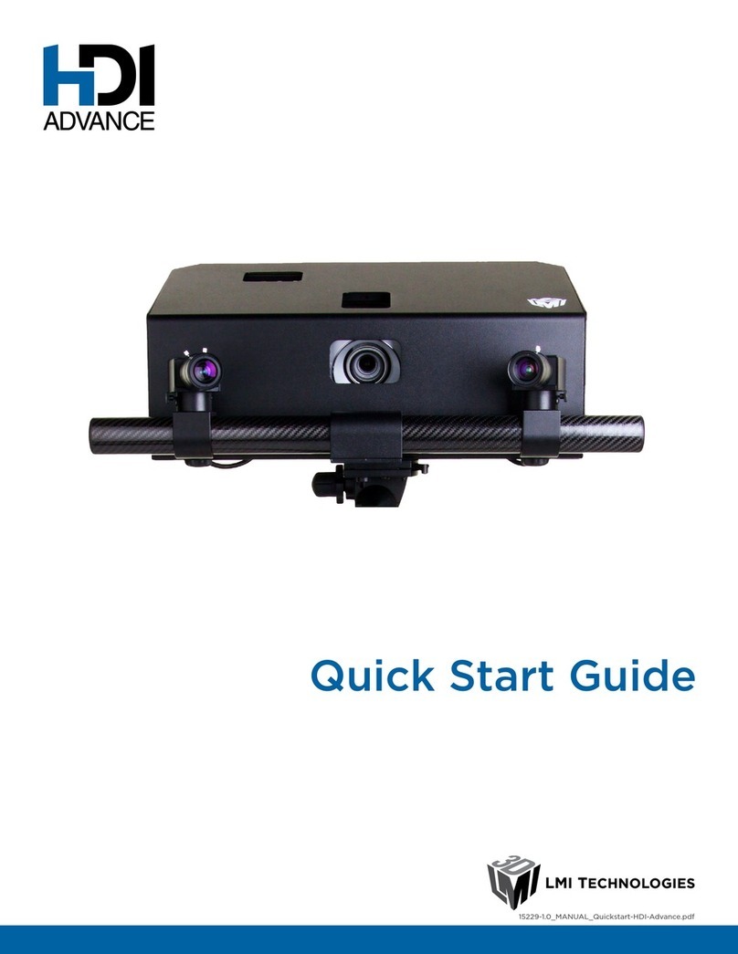
LMI Technologies HDI 120 User manual

USER MANUAL HDI 120
Version 1.0 Revision: A

2HDI 120
Copyright © 2013 by LMI Technologies, Inc. All rights reserved.
Proprietary
This document, submitted in condence, contains proprietary information which shall not be
reproduced or transferred to other documents or disclosed to others or used for manufacturing or any
other purpose without prior written permission of LMI Technologies Inc.
No part of this publication may be copied, photocopied, reproduced, transmitted, transcribed, or
reduced to any electronic medium or machine readable form without prior written consent of
LMI Technologies, Inc.
Trademarks and Restrictions
HDI™ is a registered trademark of LMI Technologies, Inc. Any other company or product names
mentioned herein may be trademarks of their respective owners.
Information contained within this manual is subject to change.
Contact Information
For more information, please contact LMI Technologies.
LMI Technologies, Inc.
1673 Cliveden Ave.
Delta, BC V3M 6V5
Canada
Telephone: +1 604 636 1011
Facsimile: +1 604 516 8368
www.lmi3D.com

3HDI 120
Introduction
The HDI 120 is a precalibrated scanner that creates digital 3D models from physical objects. HDI
scanners are congured and used with proprietary software called FlexScan3D. This guide describes the
installation and hardware of HDI 120 scanners; for the documentation of the FlexScan3D software, go to
http://manual.lmi3d.com/index.php/Main_Page.
Notational Conventions
This guide uses the following notational conventions:
!
Warning Follow these safety guidelines to avoid potential injury or property damage.
Note Consider this information in order to make best use of the product.

4HDI 120
Introduction 3
Table of Contents 4
Safety and Maintenance 5
Electrical Safety 5
Environment and Lighting 6
Scanner Maintenance 6
Getting Started 7
Overview 7
Hardware 8
HDI 120 Scanner 8
Master 100 9
HDI 120 Cordsets 10
Calibration Board (Optional) 10
Rotary Table System (Optional) 10
Travel Case (Optional) 10
Installation 11
Grounding - HDI 120 Scanner 11
Mounting and Orientations 11
Connection Setup 13
Connecting to a New Scanner 13
FlexScan3D Software Overview 15
Getting Started Page 15
Scanners Page 16
Scanner Health 17
Updating Firmware 18
Project Page 19
Settings Page 20
Advanced Settings 21
Troubleshooting 23
Mechanical/Environmental 23
Connection 23
3D Acquisition 23
Specications 24
HDI 120 24
Table of Contents
HDI 120 25
Power/LAN Connector 27
Grounding Shield 27
Power 27
Safety Input 28
Scanner I/O Connector 29
Grounding Shield 29
Digital Inputs 29
Master 100 31
Master 100 Dimensions 32
Parts and Accessories 33
WarrantyandReturnPolicy 34
Warranty Policy 34
Return Policy 34
Software Licenses 35
Support 42

5HDI 120
Safety and Maintenance
Electrical Safety
Scanners should be connected to earth ground
All scanners should be connected to earth ground through their housing. All scanners should be
mounted on an earth grounded frame using electrically conductive hardware to ensure the housing
of the scanner is connected to earth ground. Use a multi-meter to check the continuity between
the scanner connector and earth ground to ensure a proper connection. Note that if the scanner is
connected to the Master 100, the ground is already properly connected.
Minimize voltage potential between system ground and scanner ground
Care should be taken to minimize the voltage potential between system ground (ground reference for
I/O signals) and scanner ground. This voltage potential can be determined by measuring the voltage
between Analog_out- and system ground. Refer to Scanner I/O Connector (page 29) for a description of
the connector pins.
Use a suitable power supply
The +24 to +48 VDC power supply used with HDI 120 scanners should be an isolated supply with inrush
current protection or be able to handle a high capacitive load.
Use care when handling powered devices
Wires connecting to the scanner should not be handled while the scanner is powered. Doing so may
cause electrical shock to the user or damage to the equipment.
!
Failure to adhere to the guidelines described in this section may result in electrical shock or equipment
damage.

Safety and Maintenance • 6HDI 120
Environment and Lighting
Avoid strong ambient light sources
The imager used in this product is highly sensitive to ambient light hence stray light may have adverse
eects on scanning. Do not operate this device near windows or lighting xtures that could inuence
scanning. If the unit must be installed in an environment with high ambient light levels, a lighting shield
or similar device may need to be installed to prevent light from aecting scanning.
Avoid installing scanners in hazardous environments
To ensure reliable operation and to prevent damage to HDI scanners, avoid installing the scanner in
locations:
• that are humid, dusty, or poorly ventilated
• with a high temperature, such as places exposed to direct sunlight
• where there are ammable or corrosive gases
• where the unit may be directly subjected to harsh vibration or impact
• where water, oil, or chemicals may splash onto the unit
• where static electricity is easily generated
Ensurethatambientconditionsarewithinspecications
HDI scanners are suitable for operation between 0 – 50 °C and 25 – 85% relative humidity (non-
condensing). Measurement error due to temperature is limited to 0.015% of full scale per degree C.
The Master 100 is similarly rated for operation between 0 – 50 °C.
The storage temperature is -30 – 70 °C.
!
When a scanner is properly heat sunk, the dierence between ambient temperature and the temperature
reported in the scanner's health channel is less than 15 °C.
!
HDI scanners are high-accuracy devices. It is critical that the temperature of all of its components are in
equilibrium. When the scanner is powered up, a warm-up time of at least one hour is required in order to
reach a consistent spread of temperature within the scanner.
Scanner Maintenance
Keep scanner windows clean
HDI scanners are high-precision optical instruments. To ensure the highest accuracy is achieved in all
scans, the windows on the front of the scanner should be kept clean and clear of debris.
Use care when cleaning scanner windows
Use dry, clean air to remove dust or other dirt particles. If dirt remains, clean the windows carefully with
a soft, lint-free cloth and non-streaking glass cleaner or isopropyl alcohol. Ensure that no residue is left
on the windows after cleaning.
Turnodevicewhennotinuse
To maximize the lifespan of the scanner, turn o the device when not in use.

7HDI 120
Overview
HDI scanners can be connected to a computer’s Ethernet port for setup.
HDI 120
HDI SCANNER
MASTER 100
USER PC
(can be disconnected
after setup)
POWER/ETHERNET TO
MASTER CORDSET
SENSOR TRIGGER
CORDSET
Getting Started

Getting Started • 8HDI 120
Hardware
HDI 120 Scanner
CAMERAS
EMITTER
I/O CONNECTOR
POWER/LAN CONNECTOR
SERIAL NUMBER
POWER AND LIGHT
INDICATORS
Item Description
Cameras Observe light reected from target surfaces.
Light Emitter Emits structured light for scanning.
I/O Connector Accepts power and input/output signals.
POWER/LAN Connector Connects to 1000 Mbit/s Ethernet network.
Power Indicator Illuminates when power is applied (blue).
Light Indicator Illuminates when light safety input is active (amber).
Serial Number Unique scanner serial number.

Getting Started • 9HDI 120
Master 100
The Master 100 is used by the HDI 120 scanner as a controller.
Scanner IO Port
3
Master Host Port
Master Power Port
Encoder/Output Port
NOT USED
Master Ethernet Port
48V Power Supply
(Pin 1)
(Pin 1)
Connect the Master Power port to the HDI 120's Power/LAN connector using the Power/Ethernet to
Master cordset. Connect power RJ45 end of the cordset to the Master Power port. The Ethernet RJ45
end of the cordset can be connected directly to the Ethernet switch, or connect to the Master Ethernet
port. If the Master Ethernet port is used, connect the Master Host port to the Ethernet switch with a
CAT5e Ethernet cable.
Item Description
Master Ethernet Port Connects to the RJ45 connector labeled Ethernet on the Power/Ethernet to Master
cordset.
Master Power Port Connects to the RJ45 connector labeled Power/Sync on the Power/Ethernet to Master
cordset. Provides power and light safety to the HDI scanner.
Scanner I/O Port Connects to the Sensor Trigger cordset (pin 5 Trigger_in+ and pin 6 Trigger_- only).
Master Host Port Connects to the host PC's Ethernet port.
Power Accepts power (+48 V).
Power Switch Toggles scanner power.
Safety Switch Toggles safety signal provided to the scanner [O= light o, I= light on].
Trigger Button Signals a digital input trigger to the HDI scanner.
Refer to Master 100 (page 31) for pinout details.

Getting Started • 10HDI 120
HDI 120 Cordsets
HDI 120 scanners use two cordsets. First, the Sensor Trigger cordset provides digital I/O connections.
Second, the Power/Ethernet to Master cordset provides power and a safety interlock to the scanner. It is
also used for sensor communication via 1000 Mbit/s Ethernet with two standard RJ45 connectors.
M16 I/O CONNECTOR
19 PIN, MALE
OPEN WIRE
May be delivered pre-wired to
Master connector
CORDSET, SENSOR TRIGGER, Xm
M16 CONNECTOR
14 PIN, FEMALE
CORDSET, POWER/ETHERNET TO MASTER, Xm
RJ45 8 PIN JACK
RJ45 8 PIN JACK
The maximum cordset length is 60m. Refer to Scanner I/O Connector (page 29) for pinout details.
Refer to Parts and Accessories (page 33) for cordset lengths and part numbers. Contact LMI for
information on creating cordsets with custom length or connector orientation.
Calibration Board (Optional)
The calibration board can be used to automatically align the positions or orientations of the rotary table
with respect to the scanner.
Rotary Table System (Optional)
The rotary table system automates the process of performing multiple scans of a single object and
automatically aligns and merges the scans to form a 360° model. It also reduces scanning processing
time.
Travel Case (Optional)
This crushproof, IPX 7 rating travel case fully protects the scanner and its standard accessories.

Getting Started • 11HDI 120
Installation
Grounding - HDI 120 Scanner
HDI 120 scanners should be grounded to the earth/chassis through their housings and through the
grounding shield of the Power I/O cordset. HDI scanners have been designed to provide adequate
grounding through the use of M5 x 0.8 pitch mounting screws. Note that if the scanner is connected to
the Master 100, the ground is already properly connected. Always check grounding with a multi-meter to
ensure electrical continuity between the mounting frame and the HDI scanner's connectors.
!
The frame or electrical cabinet that the HDI scanner is mounted to MUST be connected to earth ground.
Mounting and Orientations
The HDI scanner is typically used on a tripod, mounted horizontally.
Scanner mounted on tripod
The scanner can however be mounted to a bracket.
Scanner mounted on robot arm

Getting Started • 12HDI 120
When mounting a scanner to a bracket, use four M5 x 0.8 pitch screws of suitable length. The
recommended thread engagement into the housing is 8 - 10 mm. Proper care should be taken in order
to ensure that the internal threads are not damaged from cross-threading or improper insertion of
screws.
When mounted on a tripod, the operating temperature range of the scanner is 0-40 °C. If the
temperature exceeds this range, the scanner should be mounted to a metal bracket. When mounted on
a bracket, the operating temperature range of the scanner is 0-50 °C.
Scanners should not be installed near objects that might occlude a camera’s view of the reected light.
!
When a scanner is properly heat sunk, the dierence between ambient temperature and the temperature
reported in the scanner's health channel is less than 15 °C.
!
HDI scanners are high accuracy devices. It is critical that the temperature of all of its components are in
equilibrium. When the sensor is powered up, a warm-up time of at least one hour is required in order to
reach a consistent spread of temperature within the sensor.

Getting Started • 13HDI 120
Connection Setup
The HDI scanner is shipped precalibrated and can produce 3D point clouds out-of-the-box using
proprietary software called FlexScan3D. For details on this software, please go to http://manual.lmi3d.
com/index.php/Main_Page.
The following sections walk through the steps required to set up the scanner to scan objects.
Connecting to a New Scanner
The FlexScan3D application can automatically congure a scanner's IP address and when necessary can
also automatically congure the host PC's network settings.
You can also manually modify a scanner's IP if necessary (see Networking Panel on page 16).
To connect to a scanner for the rst time:
1 Connect cables and apply power.
Scanner cabling is illustrated in Overview (page
7)
HDI 120
HDI SCANNER
MASTER 100
USER PC
(can be disconnected
after setup)
POWER/ETHERNET TO
MASTER CORDSET
SENSOR TRIGGER
CORDSET
2 Launch FlexScan3D.
3 Go to the Scanners Panel.
You can click directly on the Scanners panel tab
or you can click on the Scanners Panel button in
the Getting Started panel.
4 Click on the Add button.
FlexScan3D will detect the attached scanners.

Getting Started • 14HDI 120
5 Select the scanner to add.
»Click HDI 120 in the dialog box that opens.
»Click on OK.
FlexScan3D will connect to the chosen scanner.
If you wish to remove a scanner, click on Remove.
If you wish to rename a scanner, click on Rename.
6 ClickontheAuto-Congurebuttoninthe
Scanners page.
7 Click on OK in the network connection
congurationdialogs.
Dialogs will appear while FlexScan3D attempts
to congure network settings and then when
settings are successfully applied.
Refer to Troubleshooting (page 23) if you experience any problems while attempting to establish a
connection to the scanner.

15HDI 120
FlexScan3D Software Overview
This section gives you an overview of the FlexScan3D software. For details on this software, please go to
http://manual.lmi3d.com/index.php/Main_Page.
Getting Started Page
This page gives you quick access to other pages and to various resources.
1
2
Element Description
1 Quick Access Buttons Provide direct access to the Scanners and Project pages, in addition to license
information and license upgrade options.
2 Additional Resources Provides access to an online user manual, patches, and forum.

FlexScan3D Software Overview • 16HDI 120
Scanners Page
The Scanners page is where you manage scanners and access other scanner-related functions.
1
2
3
Element Description
1 Scanners Panel Contains buttons that let you add, remove, and rename scanners.
2 Sensor Panel Provides scanner information and allows you to update rmware.
3 Networking Panel Lets you manually congure the network settings of the scanner. You can also
choose to congure the network settings via DHCP.
In the Scanners panel, click on the Add button to add a new scanner. A dialog will be displayed that lets
you choose the scanner to add. To remove a scanner, click on the Remove button. To rename a scanner,
click on the Rename button.
The FlexScan3D application can automatically congure a scanner's IP address and when necessary can
also automatically congure the host PC's network settings. See Connecting to a New Scanner (page
13).
Scanner addresses can be set manually after checking Advanced Network Conguration. Scanners are
shipped with the following default network conguration:
Setting Default
DHCP Disabled
IP Address 192.168.1.10
Subnet Mask 255.255.255.0
Gateway 0.0.0.0

FlexScan3D Software Overview • 17HDI 120
Scanner Health
By default, scanner health information is not displayed. To display the Health panel, you must rst
activate this feature. (See "Advanced Settings" and "Calibrating" on page 21).
Once the feature has been activated, the Health panel will be displayed next to the Sensor panel.
The following health information is available in the Health panel:
Health Statistics
Name Description
Firmware Version HDI rmware version.
FireSync Version FireSync version.
Temperature Scanner internal temperature (C).
Memory Scanner memory utilization (MB).
Storage Scanner ash utilization (%).
CPU Scanner CPU utilization (%).
Network Network output utilization.
Uptime Length of time since the sensor was power-cycled or reset.
State The state of the scanner. State is Ready, Running, or Disconnected.
Camera 1 Errors Count of camera #1 errors.
Camera 1 Drops Count of frame drops due to camera #1 errors.
Camera 2 Errors Count of camera #2 errors.
Camera 2 Drops Count of frame drops due to camera #2 errors.
Message In Drops Number of times Ethernet data is dropped (from PC to sensor).
Message Out Drops Number of times Ethernet data is dropped (from sensor to PC).

FlexScan3D Software Overview • 18HDI 120
Updating Firmware
LMI recommends updating the rmware after installing a new version of the FlexScan3D software.
Clicking on the Update Firmware button in the Sensor panel automatically updates the scanner to the
latest rmware.

FlexScan3D Software Overview • 19HDI 120
Project Page
The Project page is where you manage projects. You can also instruct the scanner to scan objects once
a project has been created or opened, and then work with the resulting scans or with scans that were
performed previously.
1
Element Description
1 Project Panel Lets you create, open, and delete projects.
To create a new project, click on the New button in the Project panel. To open an existing project,
click on Open. To delete a project, click on Delete and select the project to delete in the dialog this is
displayed.
Once a project has been created or opened, additional tools are displayed next to the Project panel.
These tools let you perform various operations on scans.
To scan an object, either press the Trigger button on the Master 100 controller or click on the Scan
button in the FlexScan3D interface.

FlexScan3D Software Overview • 20HDI 120
Settings Page
The Settings page allows you to congure the scanner and the FlexScan3D software.
The General tab allows you to set Project and Calibration paths, and also allows you to congure
advanced mesh, post-processing, and scanning options.
By default, only the General tab is displayed. To display additional tabs, check the Show Advanced
Settings checkbox.
Other manuals for HDI 120
1
Table of contents
Other LMI Technologies Scanner manuals

LMI Technologies
LMI Technologies FocalSpec User manual

LMI Technologies
LMI Technologies HDI 109 User manual

LMI Technologies
LMI Technologies HDI 100 Series User manual

LMI Technologies
LMI Technologies chroma+scan 20 0 Series User manual

LMI Technologies
LMI Technologies Gocator 1300 User manual

LMI Technologies
LMI Technologies HDI 120 User manual

LMI Technologies
LMI Technologies MikroCAD premium User manual

LMI Technologies
LMI Technologies Chroma+scan 21X5 User manual

LMI Technologies
LMI Technologies MikroCAD User manual

LMI Technologies
LMI Technologies HDI Advance User manual