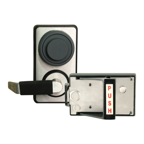
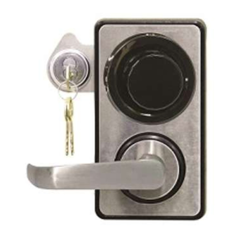
LockMasters X-Lock X-O7 User manual

DELUXE HIGH
SECURITY SET
LKM116 INSTRUCTIONS
S&G 8400/8500 DRILL GUIDE
LKM115 INSTRUCTIONS

The X-Lock Dial Puller & Drill Guide is a unique set of tools that have been designed to aid
the safe technician in neutralizing a lock out on the Mas-Hamilton/Kaba Mas X- Lock Series.
Although the X-Lock Dial Puller & Drill Guide is simple to use, it will nevertheless be wise
for all new owners and users to read this book with care. Keep in min as you read, and as
you begin to use the X-Lock Dial Puller & Drill Guide that it is, in a sense, a hand tool. Like
any other hand tool, continued use and practive will increase the operator’s skill. Power
tools will be required in the use of the X-Lock Dial Puller & Drill Guide.
GENERAL SAFETY INSTRUCTIONS FOR POWER TOOLS
Know Your Power Tool
Read and understand the owner’s manual and labels affixed to the tool.
Ground All Tools
Ensure your tools has an approved 3 conductor cord and a 3 prong grounding
type plug to fit the proper grounding type receptacle.
Keep Work Area Clean
Cluttered areas and benches invite accidents. Floor must not be slippery
due to waxes or other liquids.
Keep Children Away
All visitors should be kept a safe distance from your work area.
X-O7 DIAL PULLER INSTRUCTIONS
STEP 1 - Insert the X-O7 dialspacer ring inside the
puller cup handle and align the 3-pointed hex sctews
with the X-O7 dial spacer ring. Thread the three screws
into tthe spacer to hold it in place.
Follow steps 2-8 to remove dial.
NOTE: The spacer ring is only used when pulling the
dial on an X-O7 lock.
X-O7 DIAL PULLER & DRILL GUIDE
COMPONENTS
PULLER CUP
CUP HANDLE
PULLER BOLT
SPINDLE BOLT
3/32” , 3/16”, 9/64” & 5/32”
ALLEN WRENCHES
X-O7 DIAL SPACER RING
SPINDLE KNOB
8400/8500 DRILL GUIDE
FENCE DRILLING
JIG & DRILL X-LOCK DRILL GUIDE

STEP 2 - Place the Puller Cup over the nose of the dial,
which will self-center over the spindle. Use the provided
3/16” Allen wrench and firmly tighten the
3-pointed Hex head screws. Tighten pointed Hex head
screws until the start biting into the nose of the dial.
STEP 3 - Thread the Cup Handle onto the Puller Cup
and hand tighten.
STEP 4 - Thread the Spindle Bolt into the center of the
Puller Cup until it stops. The guide hole in the center of
the Spindle Bolt will accommodate a 1/4” high-speed drill
bit. The dial is aluminum and zinc alloy so it is very soft.
The best approach to drilling is a sharp drill bit, low RPM
and moderate pressure. Hold your drill in one hand and
the Cup Handle in the other to insure the dial does not
spin as the drill is turning.
STEP 5 - There are two hardened set screws that hold
the dial onto the spindle, this will be the stopping point.
The depth from the face of the dial nose to the first set
screw is 7/32”. Using the Spindle Bolt as a guide, drill
into the Dial Nose until you feel a vibration, this is the
drill bit making contact with the first hardened set-screw.
Stop drilling at this point.
STEP 6 - Remove the Spindle Bolt from the Puller Cup
and replace it with the Puller Bolt. The Puller Bolt has
an extension rod that will make contact with the dial
spindle. Using a adjustable wrench or a 15/16” box end
wrench and holding firmly onto the Cup Handle, start
threading the Puller Bolt clockwise into the Puller Cup.
The dial will start separating from the spindle.

STEP 7 - The distance required to completely remove
the dial is approximately 3/8” from the bottom of your
drilled hole or 9/16” from the face of the Puller Cup.
When the dial has been removed, the Puller Cup can
be separated from the dial by loosening the 3-set
screws. Remove the Spindle Bolt from the Puller Cup
and set aside.
STEP 8 - The Spindle Knob provides turning torque
needed to retract the bolt after the hole has been
drilled. The Spindle Knob attaches to the Spindle with
a set-screw. Use the 3/32” Allen wrench to tighten the
Spindle Knob to the Spindle.
X-07 Dial Replacement Parts
Note: Replacement parts for the X-07
are no longer available.
X-08 Dial Replacement Parts
Note: Replacement parts for the X-08
are no longer available.
X-09 Dial Replacement Parts
MAS504068 X-09 Snap-on Dial
MAS501226 X-09 Hub Assembly
MAS504069 X-09 Spindle 4.5”
MAS104017 Tube Kit 4.5”

THE X-LOCK DRILL GUIDE OPERATION
The X-Lock drill guide has four drill points
mapped out. Hole P targets the pin on the
X-O7 lever. This will usually be the primary
drill point because the pin is located well
inside the diameter of the dial ring, making
repair much easier. Hole L targets the X-O7
lever screw which is usually the secondary
drill point since this hole is located near the
perimeter of the dial ring making repair a
little more difficult. Hole L targets the internal
relock device on all X-Locks. Hole M targets
the motor gear on the X-O8 and X-O9 lock,
which is the primary drill point for these locks
With the dial ring removed attach the drill
guide to the container using the 8-32x5/8”
cap screws provided. Notice the eight mount-
ing holes. The four inner most holes are for installation on a Mosler container, the four
outer most holes are for Hamilton, Overly HHM, etc.
The layout of the attaching screws will allow the drill guide to be mounted in four differ-
ent positions depending on the handling of the lock, vertical up (VU) vertical down (VD)
right hand (RH) left hand (LH). The drill guide is marked with an arrow and “Bolt Side”
stamped on it.
Spindle Knob
The Spindle Knob attaches to the spindle with a set screw.
Use the 3/32” Allen wrench provided to tighten the set screw
to the spindle. The Spindle Knob provides the turning torque
needed to dial the lock and to retract the bolt.

8400/8500 DRILL GUIDE
The 8400/8500 Drill Guide is a unique
drilling template that has been designed
to target the fence, relock and lever
screw on Sargent & Greenleaf 8400 and
8500 Series Group I Combination Locks
with the Spy-Proof dial and dial rings.
The 8400/8500 Drill Guide attaches
directly to the dial ring with 4 hex head
cap screws. There are 2 additional hex
head cap screws that will stabilize the
dial. There is no need for dial or dial ring
removal. The 8400/8500 Drill Guide is
designed to target the fence, relock and
lever screw in any of the 4 mounting
positions of the lock. There is no techni-
cal expertise needed to lay out drill points.
lthough the 8400/8500 Drill Guide and Fence Drilling Jig are simple to use, it will never-
thelesss be wise for all new owners and users to read this book with care. Keep in mind
as you read, and as you begin to use the 8400/8500 Drill Guide and Fence Drilling Jig
that it is, in a sense, a hand tool. Like any other hand tool, continued use and practice will
increase the operator’s skill. Power tools will be required in the use of the 8400/8500 Drill
Guide and Fence Drilling Jig.
8400/8500 Drill Guide Operation
The 8400/8500 Drill Guide has been specifically designed to fit over the Spy-Proof dial
and dial ring of the Sargent & Greenleaf 8400 or 8500 Series locks.
There are 2 index pins that will align the 8400/8500 Drill Guide to the Spy-Proof dial and
dial ring.
Once the 8400/8500 Drill Guide is in place, tighten the 4 hex head cap screws at 20, 40,
60 and 80 to the dial ring with the 3/16” Allen wrench provided. Then tighten the 2 hex
head cap screws at 90 and 10 to the dial. There are 2 purposes for these last 2 hex head
cap screws. First, to stabilize the dial at “0”, the position at which the lever will drop, and
secondly, to provide more holding power for the 8400/8500 Drill Guide.
The drill guide is made in 2 pieces. The outer cup, which remains stationary when secured,
and the inner template which can be rotated to compensate for the hand of the combination
lock. The drill guide in the diagram is set up to drill a right hand mounted lock. When it is
necessary to change the handing of the drill guide, remove the 2 cap screws located on the
front of the drill guide. Rotate the inner template for the desired lock handing to the index
mark located on the right hand side of the outer cup. Once the inner template has been
positioned, replace the 2 cap screws in the front.
There are 3 drill points mapped out on the drill guide. Hole A will be the primary target
which is the location of the fence. Hole B will usually be the secondary target and is the
location of the lever screw. Drilling for the lever screw is more difficult since you have little
margin for error. Hole C is used to neutralize the internal spring-loaded relock.
It is suggested that your finish hole be 5/16” in diameter. This will allow for extra room
to maneuver within the drilled hole in order to neutralize the fence or the lever scrw. The
use of this tool requires a 6” drill bit.
INDEX PIN
INDEX
MARK
V U
R H
V D
L H

Tips for Drilling the Fence
All you have to be is close. Close enough that
is to bend the fence towards the center of the
drilled hole. With this accomplished, there are
a couple of ways to eliminate the fence. You
could try drilling it off freehand, use a hole saw
to remove that portion of the lever holding the
fence or use the Fence Drilling Jig provided
with the 8400/8500 Drill Guide. The Fence
Drilling Jig has 2 parts, the tube with knurled
brass handle and 6” extension drill and the 2
parts together.
The Fence Drilling Jig is designed to aid the safe technician in removing the fence
on combination locks whose fence is coming towards you as it is on some Sargent &
Greenleaf, LaGard and Ilco locks. The drilled hole size cannot be less than 1/4” and the
depth from the face of the safe to the lever shoudl not exceed 3-1/2”. It is not ciritical for
the drilled hole to be centered on the fence. If your drilled hole is off center, use an ice
pick or similar tool to bend the fence towards the center of the drilled hole. To use, insert
the drill into your hand held drill motor. Insert the tube into the drilled hole of the safe.
While twisting the tube back and forth, slide the tube onto the fence allowing it to bottom
out on the lever. Hold the tube firmly, insert the drill into the tube, turn on the drill motor
and carefully drill away the fence. The depth required to completely remove the fence
from the lever is 5/8” for a 3 wheel lock. For a 4 wheel lock, the depth required is 3/4”.
INDEX
MARK
V U
R H
V D
L H
A
B
C
A-Fence
B-Lever Screw
C-Relock

2101 John C. Watts Drive • Nicholasville, Kentucky 40356
800.654.0637 • 859.885.6041 • Fax 859.885.7093
www.lockmasters.com • [email protected]
LKM116_LKM115INST Copyright © 2011 Lockmasters Inc. 10/11
This manual suits for next models
2
Table of contents
Other LockMasters Lock manuals