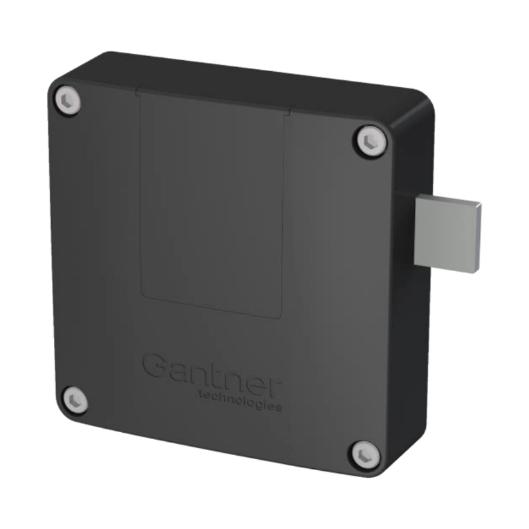
Gantner GAT SMART.Lock 7000 System Quick guide

www.gantner.com
HB_GAT-SMARTLOCK7000--EN_10
1
GAT SMART.Lock 7000 System
Electronic wired locking system
W
Installation, Configuration, Operation
Document Version 1.0


GAT SMART.Lock 7000 System
www.gantner.com
HB_GAT-SMARTLOCK7000--EN_10
3
Copyright 2014, GANTNER Electronic GmbH, Schruns (Austria).
General warning and safety instructions
Dear customer,
We congratulate you on having selected a product (appliance or software) from GANTNER Electronic GmbH. Our aim is to ensure
that our product operates with safety and to your complete satisfaction. To achieve this aim please take this opportunity to familiar-
ise yourself with the following guidelines:
1. Installation, commissioning, operation and maintenance of the purchased product must be carried out in accordance with the
instructions, i.e., in accordance with the technical conditions of operation as described in the corresponding product documen-
tation.
2. Before installation, commissioning, operation, or maintenance it is therefore essential that you read the corresponding chapter
within this manual and observe its instructions.
3. If there are still some points on which you are not entirely clear, please do not take a chance. All queries can be clarified by
your GANTNER company representative or by contacting the GANTNER Electronic GmbH hotline.
4. Where not otherwise specifically documented, the appropriate installation, commissioning, operation, and maintenance of the
product is the customer’s responsibility.
5. Directly on receipt of the goods, inspect both the packaging and the product itself for any signs of damage. Also check that
the delivery is complete and includes all accessories, documentation, and auxiliary devices, etc.
6. If the packaging or product has been damaged in transport or should you suspect that it may have a fault, the product must
not be put into service. In this case, contact your GANTNER company representative. The representative will make every ef-
fort to resolve the problem as quickly as possible.
7. Installation, commissioning and servicing of our appliances must only be carried out by suitably trained personnel. In particu-
lar, electrical connections must only be made by correspondingly qualified specialists. All applicable installation provisions in
accordance with the relevant national Electrical Engineers construction regulations (e.g., ÖVE, [Austrian] VDE, [German]...)
must be observed.
8. Where not otherwise stated, installation and maintenance work on our appliances must be carried out when disconnected
from the power supply. This applies in particular to appliances which are normally supplied by low-voltage current.
9. It is prohibited to make alterations to the appliances, or to remove protective shields and covers.
10. Do not attempt to repair an appliance yourself after a defect, failure or damage, or to put it back into operation again. In such
cases, it is essential you contact either your GANTNER company representative or the GANTNER Electronic GmbH hotline.
11. GANTNER Electronic GmbH accepts no responsibility for any injuries or damage caused as a result of improper use.
12. Although every care is taken and we are continuously aiming for improvement, we cannot completely exclude the possibility
of errors appearing in our documentation. GANTNER Electronic GmbH therefore accepts no responsibility for the complete-
ness or the accuracy of this manual. The right is reserved to make alterations and we may carry out alterations at any time
without prior notice.
13. Should you discover any fault with the product or in its accompanying documentation, or have any suggestions for improve-
ment, you may confidently approach either your GANTNER company representative or GANTNER Electronic GmbH directly.
4
!

GAT SMART.Lock 7000 System
4
HB_GAT-SMARTLOCK7000--EN_10
www.gantner.com
14. However, even if you just want to tell us that everything has functioned perfectly, we still look forward to hearing from you.
We wish you a successful application of our product and look forward to welcoming you as a customer again soon.
Contact address / manufacturer:
GANTNER Electronic GmbH
Montafonerstrasse 8
A - 6780 Schruns/Austria
Tel.: +43 5556 73784 - 542
Fax: +43 5556 73784 - 8020
E-Mail: info@gantner.com
Web: www.gantner.com

GAT SMART.Lock 7000 System
Table of Contents
www.gantner.com
HB_GAT-SMARTLOCK7000--EN_10
5
TABLE OF CONTENTS
1. Introduction ..................................................................................................................................................7
1.1 About this manual ...................................................................................................................................7
1.2 Contact for Enquiries...............................................................................................................................7
2. General Information .....................................................................................................................................9
2.1 System Parts...........................................................................................................................................9
2.2 Ordering Guide......................................................................................................................................10
2.3 GAT SMART.LockAxx 6350 Central Reader........................................................................................12
2.4 Basic Function of the GAT SMART.Lock 7001 System........................................................................13
2.5 Term Definitions....................................................................................................................................13
3. Installation ..................................................................................................................................................15
3.1 Definition of the Door Hinge..................................................................................................................15
3.2 Measurement Diagrams for the Installation ..........................................................................................17
3.2.1 Door Width.....................................................................................................................................17
3.2.2 GAT SMART.Lock 7001 Housing..................................................................................................18
3.2.3 Door Shackle and Mounting Plate .................................................................................................18
3.2.4 Important Measurements for the Installation .................................................................................19
3.3 Mounting the GAT SMART.Lock 7001 on the Inner Side of the Locker ...................................................20
3.4 Mounting the GAT SMART.Lock 7001 in the Locker Intermediate Wall...............................................20
3.5 Mounting the Door Shackle...................................................................................................................21
3.6 Mounting Security Bolt / Emergency Opening......................................................................................23
3.7 Points to be Observed during Installation.............................................................................................23
3.8 Test Installation.....................................................................................................................................24
3.9 Replacement after a Burglary Attempt..................................................................................................24
4. Electrical Connection.................................................................................................................................25
4.1 System Structure...................................................................................................................................25
4.2 Cable Connection of the GAT SMART.Lock 7001................................................................................26
4.2.1 Power Supply.................................................................................................................................26
4.2.2 Locking Return Message...............................................................................................................26
4.3 Connection of the GAT SMART.Controller S 7000...............................................................................27
4.3.1 Connection of the GAT SMART.Lock 7001 to the GAT SMART.Controller S 7000 .....................27
4.3.2 Network Connection.......................................................................................................................27
4.3.3 Power Supply.................................................................................................................................29
4.3.4 Signalling .......................................................................................................................................31
4.4 Connection of the GAT NET.Controller M 7000 Master Controller.......................................................32
4.4.1 Connection of the GAT SMART.Controller S 7000 slave controller to the Master Controller .......32
4.4.2 Ethernet Connection ......................................................................................................................32
4.4.3 Connection of the Power Supply ...................................................................................................33
4.4.4 Signalling .......................................................................................................................................33
4.5 Connection of the "MOXA N-Port" COM Converter..............................................................................34
4.6 Connection of the GAT SMART.LockAxx 6350 Central Reader...........................................................34
4.6.1 Connection of the GAT SMART.Controller S 7000 Slave Controller and Ethernet.......................35
4.6.2 Connection of the Power Supply ...................................................................................................35
5. Configuration..............................................................................................................................................37
5.1 Configuration of the GAT SMART.LockAxx 6350 Central Reader .......................................................37
5.1.1 Open / View the Configuration of a Central Reader ......................................................................37
5.1.2 Configuration Parameters and the Corresponding Default Settings .............................................39
5.2 Configuration of the MOXA COM Converter.........................................................................................42
6. Operation ....................................................................................................................................................47
6.1 Locker User Operation..........................................................................................................................47
6.1.1 Lock a Locker.................................................................................................................................47

GAT SMART.Lock 7000 System
Table of Contents
6
HB_GAT-SMARTLOCK7000--EN_10
www.gantner.com
6.1.2 Open a Locker............................................................................................................................... 47
6.2 GAT Relaxx –Operating Software for GAT SMART.Lock 7001.......................................................... 48
6.2.1 Software Licensing........................................................................................................................ 48
6.2.2User and Role Management......................................................................................................... 48
6.2.3 General and User Interface........................................................................................................... 48
7. Technical data............................................................................................................................................ 51
7.1 GAT SMART.Lock 7001....................................................................................................................... 51
7.2 GAT NET.Controller M 7000................................................................................................................ 51
7.3 GAT SMART.Controller S 7000 ........................................................................................................... 52

GAT SMART.Lock 7000 System
Introduction
www.gantner.com
HB_GAT-SMARTLOCK7000--EN_10
7
1. INTRODUCTION
1.1 About this manual
This manual contains all the information required to install the GAT SMART.Lock 7001 electronic locker locks into
lockers. The operation procedure for the end user is also described.
In order to use the GAT SMART.Lock 7001 locks, other hardware components including the GAT SMART.Controller
S 7000 & GAT NET.Controller M 7000 control units, a MOXA Com Converter or a central reader are required in ad-
dition to PC software for configuration and control of the locker system. These system parts are also described in
this manual. Further detailed information on the additional hardware is available in separate manuals and data
sheets.
1.2 Contact for Enquiries
If you have any enquiries concerning the GAT SMART.Lock 7000 locking system please get in touch with your rep-
resentative / distributor or directly with one of the GANTNER Technology branch offices. The addresses, phone and
fax numbers are listed on the inner side of the manual cover.

GAT SMART.Lock 7000 System
Introduction
8
HB_GAT-SMARTLOCK7000--EN_10
www.gantner.com

GAT SMART.Lock 7000 System
General Information
www.gantner.com
HB_GAT-SMARTLOCK7000--EN_10
9
2. GENERAL INFORMATION
2.1 System Parts
The GAT SMART.Lock 7000 system consists of the following system parts:
Figure 2.1 - System parts of the GAT SMART.Lock 7000 system
12. Ethernet Patch Cable
1. GAT SMART.Lock 7001
5. GAT SMART.LockAxx 6350
(Central Reader)
11. GAT NET.Lock Connector
Coupling for cable connection
8. GAT NET.Power Plug 1.0
6. GAT NET.Power Supply 230V EU
Power Supply Unit
2. GAT SMART.Lock 7000 Bolt Set
(Bolt Set)
4. GAT NET.Controller M 7000
(Master Controller)
3. GAT SMART.Controller S 7000
(Slave Controller)
10. GAT SMART.Lock Cable
2m OE and … 4m OE
(2 m/4 m connection cable
with one unterminated end)
9. GAT NET.Lock Cable 4m
(Connection cable, length 4 m)
7. GAT NET.Power Cord XX
Different power cables for
the power supply

GAT SMART.Lock 7000 System
General Information
10
HB_GAT-SMARTLOCK7000--EN_10
www.gantner.com
1. GAT SMART.Lock 7001
Electronic locker lock without connection cable and bolt set.
2. GAT SMART.Lock 7000 Bolt Set
Consisting of a door shackle, door plate and a distance plate. The bolt set is mounted on the locker door.
3. GAT SMART.Controller S 7000
The slave controller is a control unit where up to 24 GAT SMART.Lock 7001 can be connected.
4. GAT NET.Controller M 7000
The master controller is a control unit to connect up to 8 GAT SMART.Controller S 7000 slave controllers. The
master controller is used to connect the slave controllers to a server / PC.
5. GAT SMART.LockAxx 6350
Central reader to check user authorisation and control the GAT SMART.Lock 7001.
6. GAT NET.Power Supply 230V EU
Power supply for the slave and master controller. Different power cables sold separately (see item 7).
7. GAT NET.Power Cord XX
Power cord for the GAT NET.Power Supply 100-240V available in different versions:
XXX = "EU" (Euro plug), "UK" (UK), "AUS" (Australia), "US" (United States of America), "IND" (India)
8. Power Plug
Plug to supply multiple controllers with a single power supply.
9. GAT NET.Lock Cable 4m
4-pin connection cable (4 m) to connect a GAT SMART.Lock 7001 to a GAT SMART.Controller S 7000 slave
controller. MOLEX connector on both ends.
10. GAT SMART.Lock Cable 2m/4m
4-core connection cable (2 or 4 m) to connect a GAT SMART.Lock 7001 to a slave controller. With one unter-
minated cable end for connecting to a customer-specific controller.
11. GAT NET.Lock Connector
Connection socket to connect two GAT NET.Lock Cable 4m.
12. Ethernet Patch Cable
Standard network cable (min. CAT 5) to connect the slave controller to the master controller.
13. COM Converter
Different COM Converters are available to convert RS 485 to Ethernet.
2.2 Ordering Guide
For the planning and ordering of the GAT SMART.Lock 7000 system components, an ordering guide is available in
a separate document (“DK_GAT-SMARTLOCK7000_Bestellhilfe-EN ").

GAT SMART.Lock 7000 System
General Information
www.gantner.com
HB_GAT-SMARTLOCK7000--EN_10
11

GAT SMART.Lock 7000 System
General Information
12
HB_GAT-SMARTLOCK7000--EN_10
www.gantner.com
2.3 GAT SMART.LockAxx 6350 Central Reader
1 Display
2 LED traffic light display (red/green)
3 Confirmation button
4 Illuminated, round scan field (to read the RFID data carriers)
5 Screw terminals for cable connection
Figure 2.2 –Central reader GAT SMART.LockAxx 6350
The GAT SMART.LockAxx 6350 is a terminal designed for reading electronic RFID (Radio Frequency Identification)
data carriers, enabling system users to identify themselves with their data carriers. The GAT SMART.LockAxx 6350
operates online, i.e., after reading a data carrier, the central reader sends a query to a higher-level host computer
and in the event of a corresponding reply, indicating that the user is authorised to open the locker, the central reader
sends a command to the corresponding slave controller to unlock/open the locker.
The central reader is connected to a host computer via Ethernet and the slave controllers are connected via the se-
rial RS 485 interface.

GAT SMART.Lock 7000 System
General Information
www.gantner.com
HB_GAT-SMARTLOCK7000--EN_10
13
2.4 Basic Function of the GAT SMART.Lock 7001 System
The GAT SMART.Lock 7001 electronic lock is the ideal solution for the convenient locking of various locker designs
in different areas of industry, logistics, organisation and education. The GAT SMART.Lock 7001 is suitable for any
type of material (sheet metal, wood, HPL, solid plastic and glass) and can be used for left and right-hinged doors
alike. Due to its slim design, the GAT SMART.Lock 7001 can also be installed in the side wall of the locker body.
The GAT SMART.Lock 7001 can be installed either on the inner side of the locker or in the locker intermediate wall.
The door shackle, which is used to lock the door, is mounted on the door.
The GAT SMART.Lock 7001 is controlled by the GAT SMART.Controller S 7000 slave controller. Up to 24 GAT
SMART.Lock 7001 locks can be connected to one slave controller unit. The slave controllers are connected to a
central reader or PC software. To open a locker the user must first present their data carrier to a reader terminal.
After valid identification and authorisation, the central reader or the PC software sends a command to the slave con-
troller that controls the corresponding lock to unlock the locker for the user.
2.5 Term Definitions
Several terms are used often in this manual and are defined as described below.
Locker:
The term "locker" in this manual refers to a wardrobe locker, a deposit locker, or similar that is locked by a GAT
SMART.Lock 7001.
Lock:
Lock is used as a general term for the GAT SMART.Lock 7001.
Slave Controller:
Up to 24 GAT SMART.Lock 7001 are connected to a GAT SMART.Controller S 7000 slave controller. The slave
controllers receive control signals via the serial RS 485 network that control the electronic locks.
Master Controller:
A GAT NET.Controller M 7000 master controller can be used to connect a slave controller via Ethernet to a higher-
ranking PC/server with control software.
COM Server:
A COM server (e.g., a MOXA COM server) can be used like a master controller to connect the slave controllers via
Ethernet to a PC/server.
Central Reader:
An electronic device (terminal) where users can identify themselves with their RFID data carriers in order to unlock
their lockers. GANTNER Electronic GmbH offers the GAT SMART.LockAxx 6350 for this function. When a user’s
data carrier has been identified as valid, the central reader sends a command to the corresponding slave controller
to unlock the user’s locker.
PC Software:
A software application that is installed on a PC or server and used to configure and control the locker system (e.g.,
the GAT Relaxx software).

GAT SMART.Lock 7000 System
General Information
14
HB_GAT-SMARTLOCK7000--EN_10
www.gantner.com
User:
A person who wants to use a locker that is equipped with a GAT SMART.Lock 7001.
Data Carrier:
Data carriers can be used by users for identification in order to unlock their lockers. This can be done, for example,
at a central reader. Contactless RFID (Radio Frequency Identification) chips are used in data carriers. The data car-
riers are available in different designs such as cards in ISO standard size, key tags, wristlets, and also for different
identification systems (LEGIC®, MIFARE®or ISO 15693).

GAT SMART.Lock 7000 System
Mounting and Installation
www.gantner.com
HB_GAT-SMARTLOCK7000--EN_10
15
3. INSTALLATION
These installation instructions describe how to install the GAT SMART.Lock 7001 locker locks. Please read
and follow these instructions carefully prior to working on the lockers or installing the locks.
As there are a wide variety of applications and locker types, a test installation that includes functional test-
ing must always be performed prior to the serial production of the lockers and the installation of the locks.
A test installation must be done before preparing the lockers and installing the locks (see chapter "3.8. Test
Installation"). Please also read the most important points for installation summarised in the chapter "3.7.
Points to be Observed during Installation"!
3.1 Definition of the Door Hinge
For the lock installation, it is important to determine whether the door is hinged to the left or the right. This is defined
as follows:
Figure 3.1 - Definition of the door hinge (right / left)
In the following pages, the installation process for right-hinged locker doors will be described. The installation pro-
cess for left-hinged locker doors is, in principle, the same as for right-hinged locker doors, only with reversed lock
and door orientation.

GAT SMART.Lock 7000 System
Mounting and Installation
16
HB_GAT-SMARTLOCK7000--EN_10
www.gantner.com
1. GAT SMART.Lock 7001
2. Fastening screws (3x) depending on the locker material
3. Door shackle
4. Door plate
5. Distance plate
6. Connection cable
7. Connection plug
8. Mounting safety / emergency opening
Figure 3.2 - Mounting overview GAT SMART.Lock 7001 for right-hinged locker doors
The GAT SMART.Lock 7001 is fastened with 3 screws (1). Depending on the type of locker, the lock can be mount-
ed on the locker side wall or in the locker intermediate wall.
On the inner side of the locker door, the door shackle is mounted with the door and distance plate.

GAT SMART.Lock 7000 System
Mounting and Installation
www.gantner.com
HB_GAT-SMARTLOCK7000--EN_10
17
3.2 Measurement Diagrams for the Installation
In this section you will find the measurement information for the hardware parts in the GAT SMART.Lock 7000 sys-
tem (lock, door shackle, etc.), and other important dimensions that must be considered during installation.
Please read and observe this important measurement information before planning and starting the installa-
tion.
3.2.1 Door Width
The minimum door width (measured from the door shackle to the hinge) is 230mm. If the door is narrower, the door
shackle will hit the locker body when the door is being closed.
Figure 3.3 - Minimum door width

GAT SMART.Lock 7000 System
Mounting and Installation
18
HB_GAT-SMARTLOCK7000--EN_10
www.gantner.com
3.2.2 GAT SMART.Lock 7001 Housing
For the length and diameter of the screws required
for installation, observe the length and diameter of
the mounting holes shown in Figure 3.4.
Figure 3.4 - GAT SMART.Lock 7001
3.2.3 Door Shackle and Mounting Plate
Figure 3.5 - Dimensions of the door shackle
Figure 3.6 - Dimensions of the door plate Figure 3.7 - Dimensions of the distance plate

GAT SMART.Lock 7000 System
Mounting and Installation
www.gantner.com
HB_GAT-SMARTLOCK7000--EN_10
19
3.2.4 Important Measurements for the Installation
Please pay close attention to the following measurements:
Figure 3.8 –Important measurements for the installation
: The centre of the door shackle must be 1 mm higher than the centre of the door shackle opening of the GAT
SMART.Lock 7001. This enables the door to close correctly, even when the door’s position adjusts within the
tolerance range of maximum 3.5 mm downwards or 1.5 mm upwards (tolerance ±2.5 mm).
: The distance between the front surface of the GAT SMART.Lock 7001 and the distance plate must be 1 to
1.5mm when the locker door is closed.
Figure 3.9 - Distance between the front surface of the lock and the distance plate

GAT SMART.Lock 7000 System
Mounting and Installation
20
HB_GAT-SMARTLOCK7000--EN_10
www.gantner.com
3.3 Mounting the GAT SMART.Lock 7001 on the Inner Side of the Locker
Observe the following instructions to mount the GAT SMART.Lock 7001 on the inner side of the locker door.
Drill the fastening holes according to the measurement diagram (Figure 3.4).
Attention: Position the holes according to the measurements shown under "3.2.4. Important Measurements
for the Installation "!
Fasten the GAT SMART.Lock 7001 onto the locker wall, observing the maximum tightening torques.
Install the connection cable and insert it into the GAT SMART.Lock 7001. The cable must be correctly installed
to allow future connection to the GAT SMART.Controller S 7000.
Note: To function correctly, the mounting security bolt must be removed from the GAT SMART.Lock 7001. Re-
move the bolt after first completing the trial installation and functional testing (see “3.6. Mounting Security
Bolt / Emergency Opening”).
3.4 Mounting the GAT SMART.Lock 7001 in the Locker Intermediate Wall
Figure 3.10 - Installation in the locker intermediate wall
Drill the fastening holes according to the measurement diagram in Figure 3.4.
Attention: Position the holes according to the measurements shown under "3.2.4. Important Measurements for
the Installation Measurements for the Installation"!
Fasten the GAT SMART.Lock 7001 onto the locker wall, observing the maximum tightening torques.
Install the connection cable and insert it into the GAT SMART.Lock 7001. The cable must be correctly installed
to allow future connection to the GAT SMART.Controller S 7000.
Note: To function correctly, the mounting security bolt must be removed from the GAT SMART.Lock 7001. Re-
move the bolt after first completing the trial installation and functional testing (see “3.6. Mounting Security
Bolt / Emergency Opening”).
Table of contents
Other Gantner Lock manuals

Gantner
Gantner GAT NET.Lock 7020 System Quick guide

Gantner
Gantner GAT ECO.Side Lock 7000 User manual

Gantner
Gantner GAT Lock 6010 B User manual

Gantner
Gantner GAT Lock 6010 F User manual

Gantner
Gantner GAT ECO.Side Lock 7010 F/ISO Quick guide

Gantner
Gantner GAT ECO.Side Lock 7000 BA Guide

Gantner
Gantner Mifare Gat ECO.Lock 7 F/ISO Series Quick guide
Popular Lock manuals by other brands

Assa Abloy
Assa Abloy Effeff 519 Installation and fitting instructions

Kwikset
Kwikset Powerbolt 250 Installation and user guide

Hoffman
Hoffman AutoLoc AUTKL400 User guide and installation manual

iglooworks
iglooworks IoT Deadbolt Installer/user guide

CDVI
CDVI I500ER manual

Safety 1st
Safety 1st OutSmart HS271 user guide