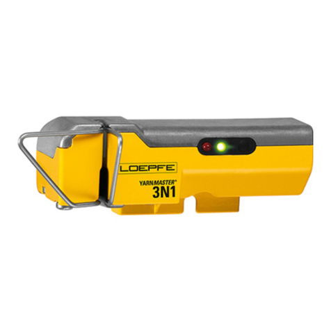
Loepfe YARNMASTER 3N1 Install guide

YARNMASTER ®3N1
46359003en
Fitting Instruction
Savio FRS 3000


Loepfe Brothers Ltd.
Kastellstrasse 10
P. O. Box 582
8623 Wetzikon/Switzerland
Phone +41 43 488 11 11
Fax +41 43 488 11 00
E-Mail service@loepfe.com
Internet www.loepfe.com
YarnMaster®is a registered trademark of Loepfe Brothers Ltd.
for Switzerland and other countries.
All further company and product names are trading names or
registered trademarks of the relative companies.
The content of this Operating Instruction is protected by cop-
yright. All rights reserved. No part of this may be reproduced
in whatever form (by printing, photocopying, microfilm or oth-
er) without a written grant of Loepfe Brothers Ltd., nor may it
be processed or distributed by any electronic mean.
Copyright©2012 Loepfe Brothers Ltd., Switzerland
03. 2012 / Version 1.0.0

43N1
INHALTSVERZEICHNIS

TABLE OF CONTENTS
Table of Contents
Safety Instructions 7
Norms and Regulations 7
Service Notes 7
Instruction Manual 8
Liability 8
Operational Notes 8
Introduction 9
About this Manual 9
Parts List 9
Principle 9
System Specifications 10
General Instructions 11
Installation 11
SCU 11
Lamp Tree 12
SCU Connections 12
Power Cable 13
Lamp Tree 13
LAN Bus to SE 13
Machine Signals 13
SE-Units 14
Installing and Connecting Detectors 18
System Setup 19
Start Up 19
Settings 19
System Test 20
Trouble Shooting 22
Service 23
F / P Functions enable / disable 23
Hardware Locks 23
Fuse and Battery Change SCU 24
Fuse and Battery Change SE 25
Replacing a SE-Board 26
Replacing a Detector 26
Spare Part Numbers 26
Software 27
SCU Software Upgrade 27
Software for Section Electronic (Q-Board) 29


73N1
SAFETY INSTRUCTIONS
Norms and Regulations
The LOEPFE YarnMaster®3N1 yarn clearing system is a prod-
uct which has been inspected for technical safety. It complies
with the following directives:
2006 / 42 / EC Machinery Directive
2006 / 95 / EC Low Voltage Directive
2004 / 108 / EC Electromagnetic Compatibility
Service Notes
The servicing of the equipment should only be performed
by qualified personnel being familiar with all safety
checks, installation and service guidelines.
Switch-off the power of the spinning machine before ser-
vicing.
The disconnection device of the “SE UNIT 3N1” is locat-
ed inside in the “SE UNIT 3N1”.
Unplug the power connector near F1 to disconnect the
“SE UNIT 3N1” from the supply.
After servicing, close all covers before starting-up the ma-
chine.
Fuse
– For continued protection against risk of fire, replace fuses
only with the same type and rating of fuse.
Battery
– Caution, risk of explosion if battery is replaced by an in-
correct type. Dispose of used batteries according to the
instructions.
Safety Instructions

83N1
SAFETY INSTRUCTIONS
Instruction Manual
To prevent faults and operating errors, we recommend to
carefully read this Instruction Manual and to carefully follow
the instructions given.
!Indicates warnings which, if not properly observed,
could harm your health, impair the functioning of
the equipment or the security of your data.
Note: The screen representations in this manual serve as il-
lustration only. They should not be used as setting examples!
A copy of this Instruction Manual must be kept easily acces-
sible near the machine.
Liability
The manufacturer assumes no liability for damage caused by:
Noncompliance with the safety, operating and mainte-
nance instructions contained in this Manual.
The use of spare parts / non-OEM parts / conversion parts
not supplied by us.
Unauthorized conversion and modification of the yarn
clearer.
Normal wear.
Operational Notes
This yarn clearing equipment may only be installed, initiated
and operated by trained personnel.
Improper operation of the equipment could cause hazards.
In accordance with 2006 / 42 / EC, 2006 / 95 / EC, 2004 / 108 /
EC. Do not open any covers (cooling, fire protection, contami-
nation, spark interference etc.)
Do not open any sensing head.
Electronic components and assemblies (printed circuit
boards) are endangered by electrostatic charges! Be-
ware of touching the soldered connectors, pin contacts be-
fore they have been discharged statically. Hold the units at
the periphery only.

93N1
SYSTEM SPECIFICATIONS
Introduction
Warning: Switch off all the power sources from the machine and make sure it has come to a standstill before
starting the installation or servicing. Follow the safety instructions in the machine’s technical documentation.
About this Manual
This manual applies to the standard Loepfe 3N1 ready quality control system 1 for Savio FlexiRotorS 3000 rotor spinning
frames. In this manual, quality is abbreviated as Q, foreigner fibre as FF and polypropylene as PP.
This manual has been written for software A700909 V8.08.
Parts List
LOEPFE Description Quantity Savio
LOEPFE Description Quantity
A280066600 SCU and Software Basic 1 per machine
A280066300 SCU and Software Full 1 per machine
A250438100 SE for 48 units Basic 1 per 2 sections
A250438000 SE for 48 units Full 1 per 2 machines
A905264100 SH for 24 Untis Basic 1 per section
A905264000 SH for 24 Untis Full 1 per machine
A589760000 Accessory cable set 1 per machine
Principle
Machine Head First Section Last Section
Empty SE LOEPFE SE LOEPFEElectronic Board
Savio
Right Side Savio
Section Controller
Left Side Savio
Section Controller
Power
SCU
n-11 n1 24
1 24 n-11 n
Ground
LAN-Communication
Top View

10 3N1
SYSTEM SPECIFICATIONS
System
Concept Modular, integrated in spinning System / Components individually replaceable / Power supply
depends on machine type
SCU One control station per machine / Date and time indication / Data memory in case of power
failure / Bus connection to section electronic / Data connection to machine control station
LAN connection to local network
Operating Setting of the conventional clearing parameters via touch screen
Operating temperature +0° up to +50° C
Humidity Up to max. 95% relative humidity not condensing
Section electronic 1 Board per Section (24 Rotors)
Sensing head 1 Sensor per rotor
Range of application For staple-spun yarn of natural, synthetic or blends
Central Unit (SCU)
SCU Graphics-capable display backlit and, touch screen Keyboard and mouse connection via USB
possible Microsoft ®Windows CE ®
Connection 24V DC SELV, +25% / -15% Max. Current: 4A / Fuse: 2xT3.15AL
FRS3000: Up to 480 clearers can be connected
Settings / side FRS3000: 2 different settings (each side)
Dimension Approx. 483 x 266 x 83 mm (W x H x D)
Max. power consumption - no lamp tree is connected: 30 Watt
- lamp tree with lamps of 3W is connected: 45 Watt
- lamp tree with lamps of 5W is connected: 53 Watt
Weight Approx. 5.25 kg
Printing Printout via USB stick
Evaluation Unit (Section Electronic)
SE-Board 24 rotors
Spinning speed Up to 400 m / min (LOEPFE side)
Max. power supply and consumption
(incl. SH)
Basic: max. 675 mA at 24V DC SELV, +25% / -15%
Full: max. 750 mA at 24V DC SELV, +25% / -15%
Max current: 1.1A / fuse: 1xT2AL.
Sensing Head
Basic 1 Sensor for diameter measurement integrated
Full 3 Sensor for Q / F / P measurement integrated
Yarn Count Range (Optical scanning principle)
TK Type Limit Range Coarse Limit Range Fine
Sensor basic / full Nm 5 Nm 100
System Specifications
113N1
INSTALLATION
!
General Instructions
Attention
– Make sure cables are not jammed, bent or stretched.
– Keep cables away from hot surfaces.
– Route cables in existing cable channels. If no cable channel is available, fix with cable ties to the ma-
chine’s stationary parts and avoid moving parts to touch cables.
– Do not block ventilation openings of SCU with cables. Allow air circulation.
Installation
SCU
Open SCU front door
The SCU is installed in the headstock at the right side of the Savio PC.
1. Add the SCU earth wire to the earth stud located at the right side in the SCU opening.
Put the ring tongue between a spring washer and washer. (see picture below)
2. Install the SCU. Use the four screws M6 x 20 DIN85 and finishing washers
3. Open the SCU connections cover (4 screws) to connect the cables that are routed to
the SCU backside.
Compact Flash
(Detail)

12 3N1
INSTALLATION
Lamp Tree
Lamp tree set A589759.
1. Use ready made holes on top of the headstock.
2. Put the grommet in the cable hole.
3. Put cable through the mounting foot and grommet.
4. Mount the foot with the four screws M6x16 DIN912 at the top side and four washers M6 DIN125, four spring washers
DIN6798 and four nuts DIN934 at the bottom side.
5. Fix the lamp tree in the foot.
6. Route the cable to the SCU.
60mm ± 0.2
mounting foot outline
4 mounting holes
Ø 6.5 mm (deburr)
60mm ± 0.2
cable hole Ø 10 mm (deburr)
insert grommet A577840
SCU Connections
LAN to SE (A5005113) SCU
Machine signals (A500750)
Power (A5006221)
Savio control box
KA5 / KA7
Relays
X15
Power connection block
!LOEPFE 3N1 device is supplied with 1 lamp tree set only.

133N1
INSTALLATION
Power Cable
Cable A5006221
1. Connect the wire ends of the power cable to 24VDC of
the Savio power connection block:
– blue = negative (–) = terminal 500
– brown = positive (+) = terminal 503
2. Route the cable to the backside of the SCU and plug in
the SCU Power connector.
Lamp Tree
Connect the lamp tree cable to the SCU Lamp tree R(ight)
connector.
Connection (R) Wire
aux no connection
blue lamp green
orange lamp brown
red lamp white
common yellow
LAN Bus to SE
Parts: 1 x cable A5005113.
Plug one cable in the SCU SE Bus connector and route the
cable in the left cable channel to the first SE Board.
KA5/KA7 give to the SCU the run/stop state of each machine
side.
Machine Signals
Cable A500750.
1. Plug the connector labeled “right” in the SCU
Machine signals R(ight) connector.
2. Plug the connector labeled “left” in the
Machine signals L(eft) connector.
3. Route the cables to the Savio control box.
4. Plug “X15” in the Savio X15 connector.
5. Connect the remaining wires to the KA5 and KA7 relay
contacts.
6. Close the SCU connections cover.
Wire Relay / contact Terminal Side
white KA5 / COM 562 Right (DX)
brown KA5 / NO 563
green KA7 / COM 564 Left (SX)
yellow KA7 / NO 565
KA5 / KA7
X15

14 3N1
INSTALLATION
SE-Units
Preparation of the SE-Units
Parts: SE-Units A250438 / A2504381, label set A579664, earth wire A5004037 and fixation parts.
1. Fix the earth wire to the SE-Unit:
2. Stick the largest labels on the SE Unit bottom (see figure 5, page 18).
3. Stick the smallest labels near the first and last detector connector at both sides (see figure 5, page 18).
4. Each machine section module has a SE -Unit: one for both machine side. Please set the right address:
– Nut DIN934 R366105
– Ring tongue
– Nut DIN934 R366105
– Washer DIN125 R367380
– Contact spacer B367380
Backside
– Washer DIN125 R367380
Bolt M 6 x16 DIN933 A577501
Machine module number 1 2 3 4
Detector number labels
SE Label
Adress DIP-switches
Numbering starts
near headstock
Machine module number 5 6 7 8 9
Detector number labels
SE Label
Adress DIP-switches
Machine module number 10 11 12 13 14
Detector number labels
SE Label
Adress DIP-switches
Machine module number 15 16 17 18 19
Detector number labels
SE Label
Adress DIP-switches
Machine module number 20 21
Detector number labels
SE Label
Adress DIP-switches
1 12 13 24 25 36 37 48
1 12 13 24 25 36 37 48
49 60 61 72 73 84 85 96 97 108
49 60 61 72 73 84 85 96 97 108
109 120
169 180
229 240 241 252
181 192 193 204 205 216 217 228
121 132 133 144 145 156 157 168
109 120
169 180
229 240 241 252
181 192 193 204 205 216 217 228
121 132 133 144 145 156 157 168
12 717 2
14 919 4
11 61621 1
13 818 3
10 51520

153N1
INSTALLATION
Cabling
Overview of the cables of one machine module (1 SE Module):
DIP switch
Route the cables for the SE -Unit in the left cable channel.
Module 1: A5005113
from SCU, Other
modules: A5004281
Module 1: A500425
from Savio power supply,
Other modules: A500752
Savio right section
controller A500429
Savio left section
controller A500429
(B338810)
(A5004281)
(A500752)
Next machine
module
Right machine front
Left machine front
() = not used for last module
Address
Power
SE-bus
Earth
(A5004037)
(A500426)
Top View

16 3N1
INSTALLATION
Location of the SE-Unit
Power for First Machine Module
Parts: 1 x power cable A500425, labels “+”, “–“, grommets
1. Connect the wires of one power cable to the power supply
GS14(SX) and label the wires:
– brown wire = positive (+)
– blue wire = negative (–)
2. Route the cable in the left cable channel to the first SE Unit
location.
3. Put a grommet over the cable near the connector.
Power for Subsequent Machine Modules
Parts: 1x power cable A500752 per SE -Unit, grommets
1. Put a grommet over both cable ends.
2. Connect the wires to the connector of the previous power
cable.
Match the wire colors.
3. Route the cable to the next SE-Unit location.
SE-bus
Parts per SE unit: 1x data cable A500426, 1x data cable
A5004281 and 1x T-junctions B338810.
1. Insert the SE-bus cable from the previous SE-Unit location
for the same side in a T- junction B338810. For the SE-Unit
in the first machine module, the cable A5005113 comes
from the SCU.
2. Plug the short cable A500426 at the other side of the T-
junction.
3. Plug the long cable A5004281 in the remaining T-junction
socket and route the cable to the next SE Unit location.
For the last SE-Unit location, no T-junction is used.
24Vdc line to first QB
A500426 to SE unit
A5004281
to next
SE unit
A5004281 to
previous SE unit
A5004281
to next
SE unit
Machine Tail Headstock
SE-Electronic

173N1
INSTALLATION
Stop Signals
Per SE-Unit: 1 x cable A500429
1. Insert the side that is not marked “1” in the Savio section
controller as shown.
2. Route the side marked “1” to the SE-Unit location.
Mounting frame
Parts: mounting frame A754542, grommets, cable ties,
screws M 6 x25 DIN912, lock spacers DIN127.
1. Cut two grommets and put them on the data cable and
stop signal cable.
2. Put all cables on the mounting frame as shown, ±40 cm
of cable length in the frame. Fix the cables with the cable
ties.
3. Put six grommets in the empty places.
4. Fix the mounting plate to the bottom of the machine with
four screws M 6 x 25 and four lock spacers. The grommet
side should point away from the headstock
Connections
Parts: screws M 6 x 12 DIN85
1. Hook the SE-Unit in the mounting frame.
2. Insert the connectors: power connector,
SE-Bus connector and Stop Signal connector.
3. Close the SE-Unit and fix with two screws M 6 x 12.
4. Route the SE-Unit earth wire inside the Savio section
channel to reach the proper earth connection.
SH connectors
SH connectors
SE bus
Power
Stop Right side
Stop Left side
Headstock Tail

18 3N1
INSTALLATION
Installing and Connecting Detectors
Parts: detectors A9052641(basic) or A905264(full) with
cables A5008452 (2m) and A5008453 (3 m), screws
M 114 x 16, DIN 912, washers M4 DIN125, label set
A579664.
1. Mount the SH on the Savio clamp with the screw and the
washer. (Figure 1)
2. Fix the SH with the screw on Savio clamp. (Figure 2)
3. Pass, as shown on Figure 4 and connect first 6 SH cable
2 m and last 6 cable 3 m per section. (Figure 5)
4. Mark the other side of SH cable with the proper detector
number. (Figure 6)
5. Plug the connector in the corresponding detector number
on SE-unit (Figure 6).
Figure 1
Figure 3 Figure 4
Figure 2
Figure 5
Figure 6
Figure 1

193N1
SYSTEM SETUP
System Setup
Start Up
The functioning of the complete system has to be checked in any case.
After completing the installation and safety checks for the Savio machine, power on the machine and both machine sides.
1. The SCU starts up. If not, check the SCU power connection.
2. Within one minute, the LEDs of the SH of at least the first section show a blinking light.
Settings
Caution: Touch the touch screen with bare finders only. Do not use any object or tool to touch the screen. Do not push hard on
the screen, nor hit it with a heavy or sharp object. Remove the protection foil of the SCU display (touch screen).
Next table lists the settings to be done. Enter the system or user password when it is requested. The system password is known
by Savio and Loepfe installers only. The default user password is “123”. Save settings by pressing OK or .
Setting Where? Do what?
Date and
Time
Setup menu > System
Date / Time Select the current date, set current time and select the time zone.
Number
of spindles
Service menu > Machine
Configuration > Side(s)
Enter the number of spinning units of each machine side.
Note: After saving the settings, the picture in the Machine Overview page is adapted.
Number
of piecers
Service menu > Machine
Configuration > Side(s)
Enter the mumber of piecers.
Note: 3N1 can generate Q-reports per piecer.
Note: Other configuration settings are set in accordance with or by the customer.

20 3N1
SYSTEM SETUP
*Software : Vm.nn Build yymmdd
i. This is the software version of the user interface
ii. It consists of a major and a minor version number
iii. There is also a build number
iv. check if this version corresponds to what is required. If not, upgrade with USB stick or change CF card
with correct version (see chapter SCU Software Upgrade)
*IO : Axxxxxx Vm.nn
i. This is the part number and the software version for the I / O controller
*DU : xxxxxx_Vm.nn _$HHHH-LLLL
i. This is the part number, the version and the checksum for the H and L part of the flash
ii. These flashes also contain the software for the SE and the SH
*DU-QB : xxxxxx_Vm.nn _$ssss
i. This is the part number, the version and the checksum for the SE software, that is contained in the DU
flashes
*DU-SENS : xxxxxx_vm.nn _$hhhh
i. This is the part number, the version and the checksum for the SH software, that is contained in the DU
flashes
*SE (X–Y) : xxxxxx_Vm.nn $ssss-bbbb yyyyyy_vm.nn _$hhhh 12345678
i. SE (X–Y): shows the start and end positions for which the data that follows are the same
ii. xxxxxx_Vm.nn: This is the part number and the version of the SE software that was reported by the SE pro-
cessors, that process the data of positions X to Y
iii. $ssss-bbbb : ssss is the checksum of the software; bbbb is the checksum of the bootblock
iv. yyyyyyvm.nn: This is the part number and the version of the SH software that was reported by the sensing
heads, which acquire the data of positions 1 to 8 of each SE processor
v. $hhhh : hhhh is the checksum of the software
vi. 12345678 : indicates the positions for which the previous is valid. “?” means that the SH of that positions
reports another checksum. “-“ means that there is no response from that SH
vii. For instance: 1?3-5678 means that SH 2 of this SE has a different checksum and SH 4 is not found or not
responding
System Test
The start up check is described step by step as follows:
1. Carry out a download of the SE – Software. (see chap-
ter Software for SE)
Caution: During download, do not interrupt power!
2. Check all software versions. See SCU service/versions.
The following should now be displayed (depending on
machine model other software versions are possible):
Other manuals for YARNMASTER 3N1
3
This manual suits for next models
1
Table of contents
Other Loepfe Industrial Equipment manuals

Loepfe
Loepfe YARNMASTER ZENIT+ User manual

Loepfe
Loepfe YARNMASTER 3N1 Install guide

Loepfe
Loepfe YARNMASTER 1N1 User manual

Loepfe
Loepfe YarnMaster Zenit User manual

Loepfe
Loepfe YarnMaster PRISMA User manual

Loepfe
Loepfe YARNMASTER 3N1 Install guide

Loepfe
Loepfe YARNMASTER 3N1 Install guide

Loepfe
Loepfe YARNMASTER 1N1 User manual