Loepfe YARNMASTER 1N1 User manual

YARNMASTER ®1N1 / 3N1
46904003 en
Version 2.X / 08. 2014
Instruction Manual LZE-V


3
1N1 / 3N1
Loepfe Brothers Ltd.
Kastellstrasse 10
P.O.Box 582
8623 Wetzikon / Switzerland
Phone +41 43 488 11 11
Fax +41 43 488 11 00
Internet www.loepfe.com
Document title: Instruction Manual YarnMaster 1N1 / 3N1
Revision: 2.X / 07. 2014
Language: English / Original Instruction Manual
This Manual is protected by copyright and exclusively intended
for internal purposes.
Complete or partial reproduction and dissemination of this
Instruction Manual to third parties – even in form of extracts
– as well as the use and / or disclosure of the contents are not
allowed without the written approval of Loepfe Brothers Ltd.,
except for internal purposes.
YarnMaster® is a registered trademark of Loepfe Brothers Ltd.
in Switzerland and / or in other countries.
© 2014 Loepfe Brothers Ltd., Switzerland


5
Table of Contents
1N1 / 3N1
Table of Contents
1 General 9
1.1 Information on this Instruction Manual 9
1.1.1 General 9
1.1.2 Duty to Read this Manual 9
1.1.3 Availability of Instruction Manual 9
1.1.4 Loss of Instruction Manual 9
1.2 Explanation of Symbols 10
1.2.1 Symbols 10
1.2.2 Signal Words 10
1.2.3 Information 10
1.3 Liability 11
1.3.1 Information in this Manual 11
1.3.2 Delivery 11
1.3.3 Technical Modifications 11
1.3.4 Improper or False Application 11
1.3.5 Inadequate Maintenance 11
1.3.6 Loss of Data 11
2 Safety 13
2.1 Responsibility of Operating Company 13
2.1.1 Basic Information 13
2.1.2 Responsibilities 13
2.2 Requirements for Personnel 13
2.2.1 Inadequate Qualification 13
2.2.2 Specialized Personnel 13
2.3 Use 14
2.3.1 Intended Use 14
2.3.2 Incorrect Use 14
2.4 Special Risks 14
2.4.1 Electric Current 14
2.4.2 Unauthorized Modifications 14
2.4.3 Electrostatic Charging 15
2.5 Safety Devices (Emergency-stop Button) 15

6
Table of Contents
1N1 / 3N1
3 Product Description 17
3.1 General 17
3.2 Equipment Configuration 17
3.2.1 Central Unit LZE-V 18
3.2.2 Section Electronic (SE) 20
3.2.3 Sensing Head YM 1N1 / 3N1 20
3.3 TK Status LED 21
3.4 Clearer Functions / Clearer Variants 22
3.5 Identification of Components / Article Description 23
4 Technical Data 25
5 Operation of LZE-V 29
5.1 General 29
5.2 Safety 29
5.2.1 General 29
5.2.2 Personnel 29
5.2.3 Intended Operation 29
5.3 Central Unit LZE-V 30
5.3.1 Monitor 30
5.3.2 USB Interface 30
5.4 User Interface / Navigation 31
5.4.1 Menu Overview 32
5.4.2 Function Buttons (additional buttons explained per page) 33
5.5 Language Selection 34
5.6 User Password 34
5.7 Data Entry 34
5.8 Base Settings 35
5.8.1 Configuration 35
5.8.2 Shifts 36
5.8.3 System 36
5.9 Group Administration 37
5.10 Article Administration 39
5.10.1 Archive Administration 39
5.11 Article Settings 40
5.11.1 Quality (Q) (1N1 / 3N1) 40
5.11.2 Foreign Matter (F) (only 3N1) 41
5.11.3 Polypropylene (P) (only 3N1) 42

7
Table of Contents
1N1 / 3N1
5.12 Machine Data 43
5.12.1 Rotor Status Color Codes 43
5.13 Monitoring Data 44
5.13.1 Quality 44
5.13.2 Foreign Matter 45
5.13.3 Polyprop 45
5.13.4 Stops & Locks 46
5.13.5 Piecings 46
5.13.6 Q-Pack 47
5.13.7 Hitlist 48
5.14 Reports 49
6 USB (Export / Import) 51
6.1 Upgrades 51
6.2 Data Export / Import 52
6.3 System Snapshot 54
6.4 Customer Logo 54
7 Inspection and Maintenance 55
7.1 General 55
7.2 Safety 55
7.2.1 Personnel 55
7.2.2 Electric Current 55
7.3 Spare Parts / Accessories 55
7.4 Cleaning the Measuring Slot 56
7.5 Diagnostics 57
7.5.1 Versions 57
7.5.2 Events 57
7.5.3 Tests 58
7.6 Replacement of Sensing Head and SE-Board 58
8 Troubleshooting 59
8.1 Hardware Locks / Recommended Action 59
8.2 Analysis of rotors with unusual behavior 60
9 Index Data Explanation 61

8
1N1 / 3N1
Abbreviations
BDE Production data collection
F Foreign matter
IPI Imperfections
LZE-V Loepfe central unit (version V)
N / S / L / T Neps / shorts / longs / thin places
OEM Original Equipment Manufacturer
P Synthetic foreign matter (Polypropylene)
Q Quality
SE Section electronics
SH Sensing head
VCV Yarn irregularities

9
General
1N1 / 3N1
If anything is not clear, contact the supplier for your own
safety.
1 General
1.1 Information on this Instruction Manual
1.1.1 General This Instruction Manual allows safe and efficient operation of yarn clearer
system YarnMaster 1N1 / 3N1.
The basic prerequisite for safe working is compliance with all specified safety
information and instructions in this Instruction Manual.
Operation as prescribed and thorough maintenance of the yarn clearer
system ensure optimum clearer performance, trouble-free operation as well
as a high service life of the yarn clearer system.
1.1.2 Duty to Read this Manual Prior to any work, the personnel must have thoroughly read and understood
this Instruction Manual and, in particular, the safety information.
1.1.3 Availability of Instruction
Manual
The Instruction Manual is part of yarn clearer system YarnMaster 1N1 / 3N1
and must be kept in direct vicinity of the equipment and accessible for person-
nel at all times.
When the equipment is sold, this Instruction Manual must be handed over to
the buyer.
1.1.4 Loss of Instruction
Manual
If you lose the Instruction Manual, ask for immediate replacement.
For contact data, see page 3.
10
General
1N1 / 3N1
In this Instruction Manual, safety information is marked with symbols and
signal words which express the extent of the hazard.
The safety information must be strictly observed to prevent accidents,
personal injuries and damage to property.
General danger
Voltage (Electrical hazard)
Risk of burns
Highly inflammable
Electrostatically sensitive components and assemblies
Grounding connection
Material damage
DANGER
WARNING
CAUTION
ATTENTION
Indicates an imminently hazardous situation which will result
in death or serious injury.
Indicates a potentially hazardous situation which may result in
death or serious injury.
Indicates a potentially hazardous situation which may result in
minor or moderate injury.
Indicates a potentially hazardous situation which may result in
damage to property.
1.2 Explanation of
Symbols
1.2.1 Symbols
1.2.2 Signal Words
1.2.3 Information Useful hints and recommendations.

11
General
1N1 / 3N1
The screenshots in this Instruction Manual serve for illustra-
tion. They are not to be used as examples for setting.
1.3 Liability
The information and safety information in this Instruction Manual have been
compiled with consideration of the applicable standards, directives and regu-
lations, the state-of-the-art and many years of experience.
1.3.1 Information in this
Manual
1.3.2 Delivery In addition to the contractually agreed obligations, the manufacturer’s General
Terms and Delivery Conditions are applicable.
1.3.3 Technical Modifications Loepfe Brothers Ltd. will not be liable for damage and accidents resulting
from the following:
Unauthorized conversion and modification of the yarn clearer system
The use of spare parts/non-OEM parts/conversion parts not supplied by us
1.3.4 Improper or False
Application
Loepfe Brothers Ltd. will not be liable for damage and accidents resulting
from the following:
Improper user of the machine
Failure to comply with the information and notices in this Instruction
Manual
1.3.5 Inadequate Maintenance Loepfe Brothers Ltd. will not be liable for damage and accidents resulting
from the following:
Neglected or inadequate maintenance
Failure to comply with the instructions described in the “Maintenance”
chapter
1.3.6 Loss of Data Loepfe Brothers Ltd. will not be liable for damage resulting from the
following:
Loss of data and operating failures caused by possible malfunctions or
defects of the machine and / or software


13
Safety
1N1 / 3N1
Risk of injuries and damage through inadequate
qualification!
Improper handling can result in severe personal injuries or
damage to the yarn clearer system.
ZInstallation, operation and maintenance must be
performed only by qualified specialized personnel.
WARNING
2 Safety
2.1 Responsibility of Operating Company
2.1.1 Basic Information The operating company of yarn clearer system YarnMaster 1N1 / 3N1 is
subject to the legal requirements for industrial safety.
It is responsible for
safe and proper operation of the yarn clearer system
qualification, training and employment of qualified personnel
2.1.2 Responsibilities The operating company shall define the responsibilities and competences
for operation and maintenance of the yarn clearer system and appoint the
responsible persons.
2.2 Requirements for Personnel
2.2.1 Inadequate Qualification
2.2.2 Specialized Personnel The following qualifications for the different areas of activity are specified in
this Instruction Manual:
User
The user is a person qualified and trained for operation and maintenance
of the yarn clearer system.
Service technician
The service technician is a Loepfe employee qualified and trained for
servicing the yarn clearer system or a person expressly named by Loepfe
for this task.

14
Safety
1N1 / 3N1
Danger to life due to electric voltage!
Immediate danger to life when touching live parts.
ZWork on electrical equipment must be performed by
persons with the appropriate qualification.
ZOnly perform maintenance work on electric components
when these are switched off, disconnected from the
mains and potential-free.
ZThe yarn clearer system may be connected to the power
supply system only when all front panels, plug-in boards
and provided covers, especially on the central unit, are
installed.
ZThe yarn clearer system may be operated only with the
standard local line voltage/frequency and with a ground-
ed protective ground contact.
DANGER
Risk of injuries and damage by unauthorized modifica-
tion of the yarn clearer system!
ZConversions or modifications of the yarn clearer system
must be agreed with Loepfe.
WARNING
2.3 Use
2.3.1 Intended Use Yarn clearer system YarnMaster 1N1 / 3N1 has been designed and built for
online yarn monitoring and clearing of undesired yarn faults on openend spin-
ning machines from various manufacturers.
The yarn clearer system must be installed and operated with observation of
the Instruction Manual and the included instructions.
2.3.2 Incorrect Use Any other or incorrect use of the clearer is considered as incorrect use and
can result in dangerous situations.
Claims of any kind resulting from damage because of incorrect use are
excluded.
2.4 Special Risks
2.4.1 Electric Current
2.4.2 Unauthorized Modifications
The manufacturer will not be liable for damaged caused by unauthorized
modification of the yarn clearer system.

15
Safety
1N1 / 3N1
Electronic components and assemblies (printed circuit
boards) are endangered by electrostatic charges!
Possible damage when touching the components!
ZHold assemblies only at the edge.
XDo NOT touch soldered connectors, pin contacts, printed
circuits or electronic components.
ATTENTION
For detailed information on the safety devices,
e.g. emergency-stop button: See Instruction Manual of the
openend spinning machine.
2.4.3 Electrostatic Charging
2.5 Safety Devices (Emergency-stop Button)
Yarn clearer system YarnMaster 1N1 / 3N1 is integrated in a openend spinning
machine and has no additional safety devices.


17
Product Description
1N1 / 3N1
All cable connections are pluggable.
3 Product Description
3.1 General Yarn clearer system YarnMaster 1N1 / 3N1 serves to clear yarn faults and
foreign matter (only 3N1) as well as quality monitoring in the spinning shop.
It is installed in openend spinning machines from various manufacturers.
The collection of the yarn faults is based on the optical measuring principle.
3.2 Equipment
Configuration
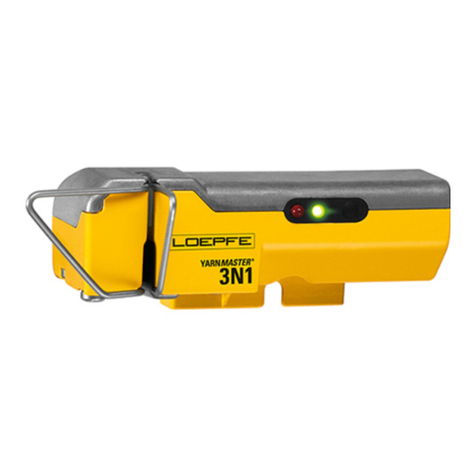
Yarn clearer system YarnMaster 1N1 / 3N1 consists of the following components:
Central unit LZE-V
Section electronics (SE)
Sensing head TK YM 1N1 / 3N1
External power supply 24 V DC
90 – 264 V AC
Central unit LZE-V
Optional: Power supply unit
24 V DC
Section Electronic (SE) – 20 or 24 Rotors Loepfe bus
8-wire cable
4-wire cable
Sensing heads 1N1 or Sensing heads 3N1

18
Product Description
1N1 / 3N1
3.2.1 Central Unit LZE-V
Central unit LZE-V consists of the following components:
Computer
User interface (touchscreen 15.6 inches)
USB port for data transfer
Central unit software
Functions:
Control and monitoring of yarn clearing
Communication with sensing heads (transfer of clearer settings)
Processing, logging and saving of operating and quality data
LZE-V Connections
Front
USB interface (USB port) for import / export of
settings and data as well as screenshots.
A removable cap protects the USB interface
from dust and humidity.

19
Product Description
1N1 / 3N1
Rear (left)
24 V DC
-
+
Marking Type Description
Power Sub D PSC Power supply 24 V DC
Contact 1 (+) 24 V DC
Contact 2 not connected
Contact 3 (–) 0 V DC
ATTENTION
Only 24 V DC may be supplied to this connection!
Threaded connection Protective ground
DANGER
This separate grounding point must be connected with
the protective ground!
PWR LED green / red Power supply OK
HDD LED red Compact-flash drive active
Microswitch
(Power ON/OFF)
LED green Tap
< 1 second
Switch to standby mode controlled by
operating system
(LED becomes orange)
LED green Press
> 1 second
Only in emergencies!
Forced, uncontrolled switch to standby
mode
(LED becomes orange)
Unsaved data are lost!
LED orange Tap
< 1 second
Start
(LED becomes green)
LAN 1 / LAN 2 RJ45 Port LAN 10 / 100 / 1000 MBit/s
USB 2.0 USB port
Display port (HDMI) DP, maximum resolution 1600 x 1200
COM 1 Sub-D, 9-pole connector RS 485
COM 2 Sub-D, 9-pole connector RS 232

20
Product Description
1N1 / 3N1
The sensing head consists of the following components:
Sensors for the collection of yarn faults
Integrated electronics
Software
1 Optical element for scanning the yarn diameter
2 Optical element for scanning foreign matter
3 P sensor
4 Yarn guide device
5 TK status LED
6 TK button
3
2
1
44
65
1
4 4
6
TK YM 1N1 Collections of yarn faults
TK YM 3N1 Collections of yarn faults, foreign matter and synthetic
foreign matter (PP, PE, etc.)
Sensing Head Variants
Yarn Count Range TK YM 1N1 / 3N1 Limit range coarse: Nm 5.0 / Nec 2.95
Limit range fine: Nm 100 / Nec 59.05
The SE-board is the interface between the control unit and a section of
sensing heads. It processes all quality data from the sensing heads.
3.2.2 Section Electronic (SE)
3.2.3 Sensing Head YM 1N1 / 3N1
Rear (right)
1 Q-bus
2 4k status LEDs
3 4k connector
12 3 4 5 6
4 Input status LEDs
5 Input signals
6 Output signals
5
Other manuals for YARNMASTER 1N1
1
This manual suits for next models
1
Table of contents
Other Loepfe Industrial Equipment manuals

Loepfe
Loepfe YARNMASTER 3N1 Install guide

Loepfe
Loepfe YARNMASTER 1N1 User manual

Loepfe
Loepfe YARNMASTER 3N1 Install guide

Loepfe
Loepfe YARNMASTER 3N1 Install guide

Loepfe
Loepfe YARNMASTER ZENIT+ User manual

Loepfe
Loepfe YARNMASTER 3N1 Install guide

Loepfe
Loepfe YarnMaster PRISMA User manual

Loepfe
Loepfe YarnMaster Zenit User manual