Loepfe YARNMASTER 3N1 Install guide

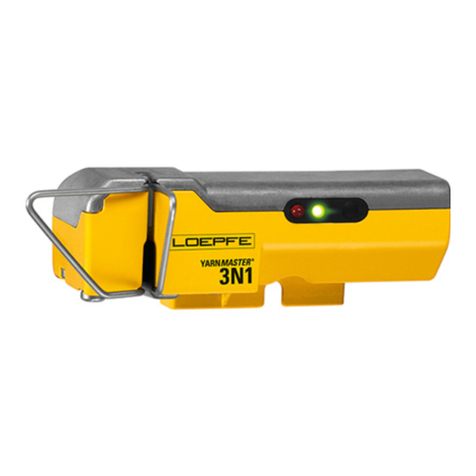
YARNMASTER ®3N1
46376003en
Fitting Instruction
RIFA RS40


Loepfe Brothers Ltd.
Kastellstrasse 10
P. O. Box 582
8623 Wetzikon/Switzerland
Phone +41 43 488 11 11
Fax +41 43 488 11 00
E-Mail service@loepfe.com
Internet www.loepfe.com
YarnMaster®is a registered trademark of Loepfe Brothers
Ltd. for Switzerland and other countries.
All further company and product names are trading names or
registered trademarks of the relative companies.
The content of this Operating Instruction is protected by cop-
yright. All rights reserved. No part of this may be reproduced
in whatever form (by printing, photocopying, microfilm or oth-
er) without a written grant of Loepfe Brothers Ltd., nor may it
be processed or distributed by any electronic mean.
Copyright©2012 Loepfe Brothers Ltd., Switzerland
03. 2012 / Version 1.0.0

43N1
INHALTSVERZEICHNIS

TABLE OF CONTENTS
Table of Contents
Safety Instructions 7
Norms and Regulations 7
Service Notes 7
Instruction Manual 8
Liability 8
Operational Notes 8
Introduction 9
About this Manual 9
Parts List 9
Principle 9
System Specifications 10
Preparation of Cabling 11
SCU Side: 11
Fitting of Sensors 12
Cabling of the Section Electronic (SE) 14
Connections to RIFA 15
Connections to PLC 15
Connections to Power Board 16
Earthing of SE-Board 18
SE Address 19
Labeling of SE-Board 19
Sensor Cables 20
System Setup 21
First Power Up 21
Settings 21
System Test 21
Service 22
F / P Functions enable / disable 22
Hardware Locks 22
Fuse and Battery Change SCU 23
Fuse and Battery Change SE 24
Replacing a SE-Board 25
Replacing a Detector 25
Spare Part Numbers 25

73N1
SAFETY INSTRUCTIONS
Norms and Regulations
The LOEPFE YarnMaster®3N1 yarn clearing system is a prod-
uct which has been inspected for technical safety. It complies
with the following directives:
2006 / 42 / EC Machinery Directive
2006 / 95 / EC Low Voltage Directive
2004 / 108 / EC Electromagnetic Compatibility
Service Notes
The servicing of the equipment should only be performed
by qualified personnel being familiar with all safety
checks, installation and service guidelines.
Switch-off the power of the spinning machine before
servicing.
The disconnection device of the “SE UNIT 3N1” is locat-
ed inside in the “SE UNIT 3N1”.
Unplug the power connector near F1 to disconnect the
“SE UNIT 3N1” from the supply.
After servicing, close all covers before starting-up the ma-
chine.
Fuse
– For continued protection against risk of fire, replace fuses
only with the same type and rating of fuse.
Battery
– Caution, risk of explosion if battery is replaced by an in-
correct type. Dispose of used batteries according to the
instructions.
Safety Instructions

83N1
SAFETY INSTRUCTIONS
Instruction Manual
To prevent faults and operating errors, we recommend to
carefully read this Instruction Manual and to carefully follow
the instructions given.
!Indicates warnings which, if not properly observed,
could harm your health, impair the functioning of
the equipment or the security of your data.
Note: The screen representations in this manual serve as illus-
tration only. They should not be used as setting examples!
A copy of this Instruction Manual must be kept easily acces-
sible near the machine.
Liability
The manufacturer assumes no liability for damage caused by:
Noncompliance with the safety, operating and mainte-
nance instructions contained in this Manual.
The use of spare parts / non-OEM parts / conversion parts
not supplied by us.
Unauthorized conversion and modification of the yarn
clearer.
Normal wear.
Operational Notes
This yarn clearing equipment may only be installed, initiated
and operated by trained personnel.
Improper operation of the equipment could cause hazards.
In accordance with 2006 / 42 / EC, 2006 / 95 / EC, 2004 / 108 /
EC. Do not open any covers (cooling, fire protection, contami-
nation, spark interference etc.)
Do not open any sensing head.
Electronic components and assemblies (printed circuit
boards) are endangered by electrostatic charges! Be-
ware of touching the soldered connectors, pin contacts be-
fore they have been discharged statically. Hold the units at
the periphery only.

93N1
SYSTEM SPECIFICATIONS
Introduction
Warning: Switch off all the power sources from the machine and make sure it has come to a standstill before
starting the installation or servicing. Follow the safety instructions in the machine’s technical documentation.
About this Manual
This manual applies to the standard Loepfe 3N1 ready quality control system 1 for RIFA RS40 rotor spinning frames. In this
manual, quality is abbreviated as Q, foreigner fibre as FF and polypropylene as PP.
This manual has been written for software A700909 V8.08.
Parts List
LOEPFE Description Quantity RIFA
LOEPFE Description Quantity
A250423500 SCU and Software Basic 1 per machine
A250437100 SE for 48 units Basic 1 per 2 sections
A905257100 SH for 24 Untis Basic 1 per section
Principle
Machine Head First Section Last Section
SE LOEPFE SE LOEPFE
Empty
Electronic Board
RIFA
PLC Controller
Power
SCU
n-11 n1 24
1 24 n-11 n
Ground
LAN-Communication

10 3N1
SYSTEM SPECIFICATIONS
System
Concept Modular, integrated in spinning System / Components individually replaceable / Power supply
depends on machine type
SCU One control station per machine / Date and time indication / Data memory in case of power
failure / Bus connection to section electronic / Data connection to machine control station
LAN connection to local network
Operating Setting of the conventional clearing parameters via touch screen
Operating temperature +0° up to +50° C
Humidity Up to max. 95% relative humidity not condensing
Section electronic 1 Board per Section (24 Rotors)
Sensing head 1 Sensor per rotor
Range of application For staple-spun yarn of natural, synthetic or blends
Central Unit (SCU)
SCU Graphics-capable display backlit and, touch screen Keyboard and mouse connection via USB
possible Microsoft ®Windows CE ®
Connection 24V DC SELV, +25% / -15% Max. Current: 4A / Fuse: 2xT3.15AL
RS40: Up to 480 clearers can be connected
Settings / side RS40: 1 setting
Dimension Approx. 483 x 266 x 83 mm (W x H x D)
Max. power consumption - no lamp tree is connected: 30 Watt
- lamp tree with lamps of 3W is connected: 45 Watt
- lamp tree with lamps of 5W is connected: 53 Watt
Weight Approx. 5.25 kg
Printing Printout via USB stick
Evaluation Unit (Section Electronic)
SE-Board 24 rotors
Spinning speed Up to 400 m / min (LOEPFE side)
Max. power supply and consumption
(incl. SH)
Basic: max. 675 mA at 24V DC SELV, +25% / -15%
Full: max. 750 mA at 24V DC SELV, +25% / -15%
Max current: 1.1A / fuse: 1xT2AL.
Sensing Head
Basic 1 Sensor for diameter measurement integrated
Full 3 Sensor for Q / F / P measurement integrated
Yarn Count Range (Optical scanning principle)
TK Type Limit Range Coarse Limit Range Fine
Sensor basic / full Nm 5 Nm 100
System Specifications
113N1
PREPARATION OF CABLING
SCU Side:
Power supply 24 V
Ground
Speed Sensor
LAN to Q-Board
The power supply must be installed by an electrician
Cabling SCU Front
Black: Power Supply from machine 24V (30W)
Red: Speed Sensor from RIFA
Yellow: LAN to SE Electronic
Blue: Ground to machine ground
Cabling SCU Backside
Preparation of Cabling

12 3N1
FITTING OF SENSORS
Fitting of Sensors
Prepare the sensors and screw the mounting piece to the
sensor.
Screw the sensing head into the existing hole of the bar and
position it in the middle of the hole of the mounting piece. It
is necessary to do it in this way to be able to make a read-
justment.

133N1
FITTING OF SENSORS
At least: the measuring slit should be in the range of the press
roller. (Picture)
If this is not so, the metal bar with with screwed on sensor
should be slided. This should be done by the mill mechan-
ics.

14 3N1
CABLING OF THE SECTION ELECTRONIC (SE)
Cabling of the Section Electronic (SE)
Yellow: LAN to SE-boards (splitter on each section)
Black: Power supply (from Power supply of RIFA)
Red: Stop cable IF to connect the SAG)
Blue: Ground from SE to machine ground
For exact cabling see the following description. Before starting with the cabling the sensors should be fitted!
View from below
Machine Head First Section Last Section
SE LOEPFE SE LOEPFE
Empty
Electronic Board
RIFA
PLC Controller
Power
SCU
n-11 n1 24
1 24 n-11 n
Ground
LAN-Communication

153N1
CABLING OF THE SECTION ELECTRONIC (SE)
Connections to RIFA
Connections to PLC
Connections
COM0 – COM1
0V OUT – COM0
PLC Controller RIFA
RIFA PLC 3N1 Stop cable
A5008541
3N1 Stop cable
A5008542
0 0
1 1
2 2
3 3
4 4
5 5
6 6
7 7
8 8
9 9
10 10
11 11
12 12
13 13
14 14
15 15
16 16
17 17
18 18
19 29
20 20
21 21
22 22
23 23
3N1 Stop cable
to SE board

16 3N1
CABLING OF THE SECTION ELECTRONIC (SE)
Connections to Power Board
24V Power cable for SE 3N1
Power Board RIFA

173N1
CABLING OF THE SECTION ELECTRONIC (SE)
Q-Board Connections
Red: Stop cable (1= Upper: A5008541, 2= Lower: A5008542)
White: Power supply 24 V from Power Board RIFA
Yellow: LAN to SCU, is splitted by each section see the following picture
Blue: Ground, connected to machine ground
1
2

18 3N1
CABLING OF THE SECTION ELECTRONIC (SE)
Output for next section (if last, empty)
Input from SCU or last Q-Board
LAN for Q-Board
Earthing of SE-Board
The screw must be screwed onto the Q-Board at the upper
left side, as illustrated.
The earthing is assured by the machine ground. The ground
wire can simply be laid along the side panel.
Machine Ground Diagram
Machine Head
RIFA
PLC Controller
RIFA
Power Supply
RIFA
SE 3N1 SE 3N1
Power Supply
RIFA
PLC Controller
RIFA
1. Machine Ground
1.
First Section Last Section

193N1
CABLING OF THE SECTION ELECTRONIC (SE)
Labeling of SE-Board
The labelling is to be done by the fitter. As soon as the Q-
Boards are placed the attached stickers must be fixed.
This marking serves for a correct cabling and helps in case
of exchange.
Blue: SE-Board number
Yellow: first and last rotor number on each side.
SE Address
Set the right address on the switch of the SE. Address sticker
is on the SE case.

20 3N1
CABLING OF THE SECTION ELECTRONIC (SE)
Sensor Cables
On each machine side:
6 cables, length 3m (SCU side, longest way to Q-Board)
6 cables, length 2m (shorter way to Q-Board)
Cable from the sensor to the inside of the machine. Use the
support (different types available).
Inside (view of the backside of the rotor)
For sensor cable layings an orderly laying is necessary to
avoid unnecessary kops. Use cable channels.
Labling of sensor cable (hanging end!!), when the cable is
plugged into the sensor and led to the inside.
Use the Rotor number as a help!!!
Other manuals for YARNMASTER 3N1
3
Table of contents
Other Loepfe Industrial Equipment manuals

Loepfe
Loepfe YARNMASTER 1N1 User manual

Loepfe
Loepfe YARNMASTER 3N1 Install guide

Loepfe
Loepfe YARNMASTER 3N1 Install guide

Loepfe
Loepfe YARNMASTER 3N1 Install guide

Loepfe
Loepfe YARNMASTER ZENIT+ User manual

Loepfe
Loepfe YarnMaster PRISMA User manual

Loepfe
Loepfe YarnMaster Zenit User manual

Loepfe
Loepfe YARNMASTER 1N1 User manual
Popular Industrial Equipment manuals by other brands

RINGSPANN
RINGSPANN Brake HW 145 FHM Installation and operating instructions

Durlum
Durlum LOOP TYPE 3 installation manual

Trane
Trane KIT15449 installation guide

ATI Technologies
ATI Technologies 39-0214 quick start guide

Eaton
Eaton Power Defense PRLSEB Series Instruction leaflet

Festo
Festo MPS 8049013 Getting started