manuals.online logo
Brands
  1. Home
  2. •
  3. Brands
  4. •
  5. Loewe
  6. •
  7. TV Accessories
  8. •
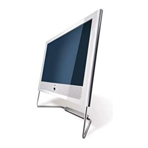
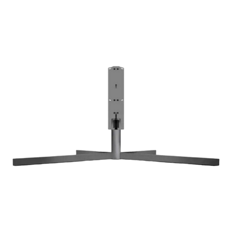
  9. Loewe Floor Stand I 55 SP User manual

Loewe Floor Stand I 55 SP User manual

240–34604 000
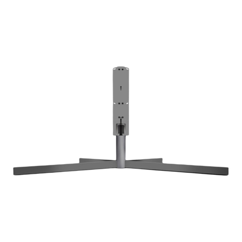
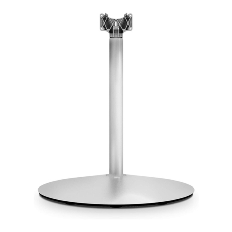
Floor Stand I 40/46 SP
Floor Stand I 55 SP
Zubehör TV, Accessori TV, Toebehoren TV,
Accessories TV, Accessoires TV, Accesorios TV
Montageanleitung, Istruzioni sul montaggio, Montage-instructis,
Installation Instructions, Instructions d´intallation, Instrucciones de montaje
2
Floor Stand I 40/46 SP
Art. Nr. 69477xxx
Floor Stand I 55 SP
Art. Nr. 69465xxx
Printed in Germany KB 04.10
Änderungen vorbehalten.
Con riserva di modifiche.
Wijzigingen voorbehouden.
Subject to modifications.
Modifications reservée.
Reservado el drecho
a modificaciones.
Deutschland
Loewe Opta GmbH
Customer Care Center
Industriestraße 11
D-96305 Kronach
D-96317 Kronach
Telefon 01801/22256393
Telefax (09261) 99500
3
Liebe Kundin,
lieber Kunde,
wir gratulieren Ihnen zum Kauf
dieses hochwertigen Produktes.
Loewe steht seit vielen Jahren für
innovatives Design, für hervorra-
gende Qualität und Funktionalität.
Damit Ihrem Produkt diese Eigen-
schaften lange erhalten bleiben,
beachten Sie bitte die Montage-
und Sicherheitshinweise dieser
Anleitung.
Floor Stand I 40/46 SP
Art. Nr. 69477xxx
ist verwendbar für die TV-Geräte:
Individual 40 LED
Individual 46 LED
Floo Stand I 55 SP
Art. Nr. 69465xxx
ist verwendbar für die TV-Geräte:
Individual 55 LED
In der Montageanleitung wird, für
den Floor Stand I 40/46/55 SP, der
Begriff Floor Stand verwendet.
Gentile Cliente,
Congratulazioni per l’acquisto di
questo pro-dotto di qualità Loewe.
Da molti anni Loewe è sinonimo di
design innovativo, qualità eccellen-
te e funzionalità.
Affinché anche il Suo prodotto
conservi a lungo queste caratte-
ristiche, La preghiamo di leggere
attentamente le indicazioni d’uso e
di sicurezza del presente manuale.
Beste klant,
Wij feliciteren u met de aankoop
van dit kwaliteitsproduct. De naam
Loewe staat al vele jaren lang
garant voor innovatief design en
uitstekende kwaliteit en functiona-
liteit.
Om ervoor te zorgen dat uw pro-
duct deze eigenschappen geduren-
de lange tijd blijft behouden, dient
u de bedienings- en veilig-heids-
instructies in deze handleiding in
acht te nemen.
Floor Stand I 40/46/55 SP
4
Floor Stand I 40/46/55 SP
Dear
customer,
Congratulations on your purchase
of this high quality product. For
many years Loewe has stood for
innovative design, excellent quality
and functionality.
Please follow the installation and
safety instructions in this manual
to ensure that your product retains
these properties for many years to
come.
Chère cliente,
cher client,
nous vous félicitons de l’achat de
ce produit de haute qualité. Depuis
de nombreuses années, Loewe
représente un design innovateur,
une excellente qualité et la fonc-
tionnalité.
Afin que votre appareil conserve
ces qualités pendant longtemps,
veuillez respecter les instructions
de commande et de sécurité de
cette notice.
Floor Stand I 40/46 SP
N° art. 69477xxx
est utilisable pour les téléviseurs :
Individual 40 LED
Individual 46 LED
Floor Stand I 55 SP
N° art. 69465xxx
est utilisable pour les téléviseurs :
Individual 55 LED
Dans les instructions de montage,
le terme Floor Stand est utilisé
pour le Floor Stand I 40/46/55 SP.
Estimada cliente,
estimado cliente:
Le felicitamos por la compra de este
producto de alta calidad. En Loewe
apostamos, desde hace muchos
años, por un diseño innovador y una
excelente calidad y funcionalidad.
Si desea que su producto conserve
todas estas características durante
mucho tiempo, le rogamos respete
siempre las advertencias de este
manual relativas a su seguridad y
montaje.
Floor Stand I 40/46 SP
Nº. de ref. 69477xxx
puede utilizarse con los siguientes
televisores: Individual 40 LED
Individual 46 LED
Floor Stand I 55 SP
Nº. de ref. 69465xxx
puede utilizarse con los siguientes
televisores: Individual 55 LED
En estas instrucciones de montaje
se empleará el término Floor Stand
para hacer referencia al Floor Stand I
40/46/55 SP.
5
Floor Stand I 40/46/55 SP
Inhalt
Sicherheitshinweise 6
Lieferumfang 8
Teile Floor Stand montieren 10
Sound Projector befestigen 12
TV-Gerät montieren 24
Technische Daten 32
Reinigung und Pflege 34
Entsorgung 36
Indice
Indicazioni di sicurezza 6
Dotazione 8
Montaggio dei componenti
Floor Stand 10
Fissare il Sound Projector 12
Montaggio dell’apparecchio TV 24
Dati tecnici 32
Pulizia e cura 34
Smaltimento 36
Inhoud
Veiligheidsvoorschriften 6
Inhoud van de levering 9
Onderdelen Floor Stand monteren 10
Sound Projector bevestigen 12
Tv-toestel monteren 24
Technische gegevens 32
Reiniging en onderhoud 34
Afvalverwijdering 36
Contents
Safety instructions 7
Scope of delivery 9
Assembling floor stand parts 10
Fastening sound projector 12
Installing TV set 24
Technical Data 32
Cleaning and care 34
Disposal 36
Contenu
Instructions de sécurité 7
Contenu de la livraison 9
Monter le Floor Stand 10
Fixer le Sound Projector 12
Monter le téléviseur 24
Données techniques 32
Nettoyage et entretien 34
Elimination des déchets 36
Índice
Advertencias de seguridad 7
Volumen de suministro 9
Montaje de las piezas del Floor Stand 10
Fijación del proyector de sonido 12
Montaje del televisor 24
Datos técnicos 32
Limpieza y mantenimiento 34
Eliminación 36
6
Floor Stand I 40/46/55 SP
Sicherheitshinweise
Beachten Sie die Informationen der
Anleitung.
Lassen Sie im Umgang mit Werk-
zeug die nötige Vorsicht walten.
Die Aufstellfläche für Ihren Floor
Stand muss eben und waagerecht
sein.
Ihr FLOOR STAND mit den mon-
tierten Geräten sollte bei einem
Standortwechsel nicht geschoben,
sondern beidseitig am Bildschirm
angehoben und getragen werden
(nicht am SOUND PROJECTOR
tragen).
Stellen oder hängen Sie bitte keine
mit Wasser gefüllten Blumenvasen,
keine brennenden Kerzen usw. auf
bzw. an Ihr Gerät. Das Gerät ist vor
Tropf- und Spritzwasser zu schüt-
zen.
Der Drehbereich Ihres Gerätes
muss frei von Hindernissen sein..
Stellen Sie Ihre Gerätekombination
so auf, dass sie, z. B. von spielen-
den Kindern, nicht umgeworfen
werden kann und für diese keine
Gefahr darstellt.
Des weiteren haben die Sicher-
heitshinweise für unsere TV-Geräte
auch hier Gültigkeit.
Norme di sicurezza
Osservare le informazioni riportate
nelle istruzioni.
Utilizzare gli attrezzi con la dovuta
cautela.
La superficie d’istallazione del Floor
Stand deve essere piana e orizzon-
tale.
In caso di spostamento, non
spingere il FLOOR STAND con gli
apparecchi collegati, ma sollevarlo
con entrambe le mani per lo scher-
mo e portarlo nel punto prescelto
(senza appoggiarlo sul SOUND
PROJECTOR).
Non collocare o appendere vasi
per fiori pieni d’acqua, candele
accese, ecc. su o all‘apparecchio.
L’apparecchio deve essere protetto
da gocce e spruzzi d’acqua.
Non ostacolare lo spazio coperto
dal raggio di rotazione dell’appa-
recchio.
Installare gli apparecchi assemblati
in modo tale da non poter essere
ribaltati, ad es. da bambini che
giocano, e da non costituire un
pericolo.
Anche in questo caso valgono le
norme di sicurezza relative ai nostri
apparecchi TV.
Veiligheidsvoorschriften
Neem de aanwijzingen in de hand-
leiding in acht.
Wees voorzichtig bij het werken
met gereedschap.
De Floor Stand moet worden op-
gesteld op een vlakke en horizon-
tale ondergrond.
Uw FLOOR STAND met de gemon-
teerde toestellen mag bij een ver-
andering van plaats niet worden
verschoven, maar moet aan weers-
zijden bij het beeldscherm worden
opgetild en gedragen (niet bij de
SOUND PROJECTOR dragen).
Gelieve geen met water gevulde
bloemenvazen of brandende
kaarsen op of tegen uw toestel te
plaatsen of te hangen. Het toestel
dient tegen druppelend en spat-
tend water beschermd te worden.
Het draaigebied van uw toestel
moet vrij zijn van obstakels.
Installeer uw toestelcombinatie
zo dat ze niet omver kan worden
gestoten door en geen gevaar
inhoudt voor spelende kinderen.
Verder gelden hier ook de vei-
ligheidsvoorschriften voor onze
tv-toestellen.
7
Floor Stand I 40/46/55 SP
Instructions de sécurité
Veuillez respecter les informations
du mode d’emploi.
Soyez prudent lors de l’utilisation
d’outils.
La surface d’installation de votre
Floor Stand doit être plane et hori-
zontale.
Lors d’un changement d’emplace-
ment, votre FLOOR STAND com-
prenant les appareils montés ne
doit pas être poussé, mais soulevé
des deux côtés de l’écran et porté
(ne pas porter par le SOUND PRO-
JECTOR).
Veuillez ne pas poser ou suspendre
de vases remplis d’eau, bougies
allumées, etc. sur ou près de l’ap-
pareil. L’appareil doit être protégé
contre les gouttes et les éclabous-
sures.
Aucun obstacle ne doit se trouver
dans la zone de rotation de votre
appareil.
Placez votre combinaison d’appa-
reils de telle sorte qu’elle ne puisse
pas être renversée, par ex. par
des enfants en train de jouer, et
ne représente ainsi aucun danger
pour eux.
Par ailleurs, les instructions de
sécurité relatives à nos téléviseurs
sont également valables ici.
Advertencias de seguridad
Respete las instrucciones del ma-
nual.
Manipule las herramientas con las
precauciones necesarias.
La superficie de colocación del
Floor Stand debe ser plana y hori-
zontal.
Si desea cambiar el lugar de in-
stalación, no arrastre el FLOOR
STAND con los aparatos monta-
dos, sino levante la pantalla por
ambos lados y llévela hasta el lugar
deseado (no la transporte por el
PROYECTOR DE SONIDO).
No coloque en el aparato ni cuel-
gue de él floreros llenos de agua,
velas encendidas, etc. Proteja el
aparato de gotas y salpicaduras de
agua.
El área de giro del aparato debe
estar libre de obstáculos.
Instale la combinación de apara-
tos de manera que no pueda ser
volcada, p. ej., por niños que estén
jugando cerca, y no represente
ningún peligro para ellos.
Por lo demás, las advertencias de
seguridad de nuestros televisores
también tienen validez en este
caso.
Safety Instructions
Refer to the information in the
manual.
You should always take care when
using tools.
The surface for installing your floor
stand must be level and horizontal.
A FLOOR STAND with the appli-
ances installed is not to be moved
by sliding but should be lifted and
carried at both ends of the screen
(not to be lifted at the SOUND
PROJECTOR).
Do not place or hang flower vases
filled with water, lighted candles
etc. on or near your set. Pro-
tect the set against dripping and
splashing water.
The rotation range of your TV set
must be kept free of obstructions.
Install the equipment so that it
cannot be knocked over, and so
that it cannot present a danger to
anyone e.g to children at play.
The safety instructions for our TV
sets also apply here.
8
Lieferumfang
Montageanleitung
(nicht im Bild)
Abb. 1
Fußkreuz (a), Säule (b),
TV-Träger (c), Schrauben (d),
Federscheiben (e) und Schrau-
ben TV (f)
Abb. 2
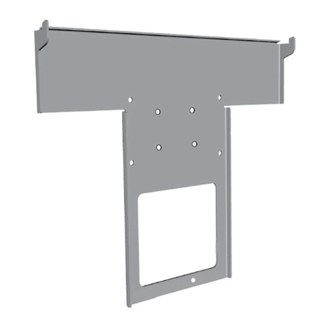
Adapterplatte
(zur Befestigung des Sound
Projectors)
Abb. 3
Befestigungsmaterial
(zur Befestigung der Adapter-
platte des Sound Projectors)
Abb. 4
Schrauber Bit T20
(zur Befestigung des TV-Ge-
rätes)
Abb. 5
Winkelschraubenschlüssel
(zur Montage von Fußkreuz,
Säule und Trägerhorn)
Abb. 6
Sicherungsschraube
(sichert den Sound Projector
gegen Aushängen)
Auspackhinweis
Zum Entfernen der Schutzfolie
und Klebebänder keine schar-
hen Gegenstände, wie Messer
verwenden. Hier könnt der
Floor Stand beschädigt werden.
Dotazione
Istruzioni di montaggio
(non in figura)
Fig. 1
Piede a croce (a), colonna (b),
Porta-TV (c), viti (d), rondelle
elastiche (e) e viti TV (f)
Fig. 2
Piastra adattatrice
(per il fissaggio del Sound
Projector)
Fig. 3
Materiale di fissaggio
(per il fissaggio della piastra
adattatrice del Sound Projector)
Fig. 4
Cacciavite Bit T20
(per il fissaggio dell’apparec-
chio TV)
Fig. 5
Chiave a brugola
(per il montaggio del piede a
croce, colonna ed elemento di
supporto)
Fig. 6
Vite di sicurezza
(impedisce il distacco del Sound
Projector)
Nota sulla rimozione dall’im-
ballo
Per rimuovere la pellicola
Floor Stand I 40/46/55 SP
f
d
a
23
5
6
1
b
c
d
e
4
f
9
Inhoud van de levering
Montage-instructies
(niet afgebeeld)
Afb. 1
voetkruis (a), kolom (b),
TV-drager (c), schroeven (d),
veerringen (e) en schroeven
TV (f)
Afb. 2
Adapterplaatje
(voor het bevestigen van de
Sound Projector)
Afb. 3
Bevestigingsmateriaal
(voor het bevestigen van het
adapterplaatje van de Sound
Projector)
Afb. 4
Schroefmachine Bit T20
(voor het bevestigen van het
tv-toestel)
Afb. 5
Hoekinbussleutel
(voor de montage van voetkru-
is, kolom en draaghoorn)
Afb. 6
Veiligheidsschroef
(beveiligt de Sound Projector
tegen loshaken)
Tips voor het uitpakken
Gebruik voor het verwijderen
van de beschermende folie
en plakband geen scherpe
voorwerpen, zoals messen.
Daardoor zou de Floor Stand
beschadigd kunnen worden
Scope of delivery
Assembly instructions
(not illustrated)
Fig. 1
Base cross (a), Column (b),
TV support (c), Screws (d),
Spring washers (e) and TV
screws (f)
Fig. 2
Adapter plate
(for fastening the sound pro-
jector)
Fig. 3
Fastening material
(for fastening the sound
projector’s adapter plate)
Fig. 4
T20 screwdriver bit
(for fastening the TV set)
Fig. 5
Allen key
(for assembling the base cross,
column and TV support)
Fig. 6
Safety screw
(to prevent the sound projector
from detaching)
Note for unpacking
Do not use any sharp objects,
such as a knife, to remove the
protective foil and adhesive
tape. This may damage the
floor stand
Eléments fournis à la
livraison
Notice de montage
(non représentée)
Fig. 1
Croisillon (a), colonne (b),
Support TV (c), Vis (d), Rondelle
(e) et Vis TV (f)
Fig. 2
Plaque adaptatrice
(pour le montage du Sound
Projector)
Fig. 3
Matériel de fixation
(pour le montage de la plaque
adaptatrice du Sound Projector)
Fig. 4
Tournevis, tête T20
(pour fixer le téléviseur)
Fig. 5
Tournevis d’angle
(pour le montage du croisillon,
de la colonne et du support)
Fig. 6
Vis d’arrêt
(empêche le Sound Projector
de basculer)
Instruction de déballage
N’utilisez pas d’objets cou-
pants, comme un couteau,
pour enlever le plastique de
protection et le ruban adhésif.
Cela pourrait endommager le
Floor Stand.
Volumen de suministro
Instrucciones de montaje
(no aparecen en la ilustración)
Fig. 1
Base en cruz (a), columna (b),
soporte del televisor (c), tornil-
los (d), arandelas elásticas (e) y
tornillos del televisor (f)
Fig. 2
Placa adaptadora
(para la fijación del proyector
de sonido)
Fig. 3
Material de fijación
(para la fijación de la placa
adaptadora del proyector de
sonido)
Fig. 4
Broca de destornillador T20
(para la fijación del televisor)
Fig. 5
Llave angular
(para el montaje de la base en
cruz, la columna y el soporte)
Fig. 6
Tornillo de seguridad
(para impedir que el proyector
de sonido se descuelgue)
Nota para el desembalaje
No utilice ningún utensilio
afilado como, por ejemplo, un
cuchillo, para retirar las láminas
protectoras y las cintas adhesi-
vas. En caso contrario, puede
dañar el Floor Stand.
Floor Stand I 40/46/55 SP
10
Floor Stand I 40/46/55 SP
Teile montieren
Beachten Sie die nebenstehen-
de Abbildung.
Beachten Sie, dass die langen
Schenkel des Fußkreuzes nach
vorne zeigen.
Sie montieren (Abb. 7) die Teile
Fußkreuz (Abb. 1a) und Säule
(Abb. 1b) mit den Federschei-
ben uter jedem Schraubenkopf,
Schrauben M6 x 16 (Abb. 1d).
(Nach oben gewölbte Seite
zum Schraubenkopf)
Zum Eindrehen und fest ziehen
der Schrauben verwenden Sie
den Winkelschraubenschlüssel
(Abb. 5),
Schrauben mit einem Drehmo-
ment von ca. 5 Nm anziehen.
(Handfest anziehen)
Stellen Sie das Fußkreuz mit
der montierten Säule auf den
Boden.
Sie montieren (Abb. 8) die
Teile, Säule (Abb. 1b) und TV-
Träger (Abb. 1c) auch mit den
Federscheiben unter jedem
Schraubenkopf.
Zum Eindrehen und fest ziehen
der Schrauben verwenden Sie
den Winkelschraubenschlüssel
(Abb. 5),
Schrauben mit einem Drehmo-
ment von ca. 5 Nm anziehen.
(Handfest anziehen)
77
8
Montaggio dei
componenti
Osservare la figura a lato.
Accertarsi che le aste del piede
a croce non sporgano in avanti.
Montare il piede a croce (fig.
1a) e la colonna (Abb. 1b)
applicando le rondelle elastiche
sotto la testa di ciascuna vite,
viti M6 x 16 (fig. 1d).
(La parte incurvata verso l’alto
è rivolta verso la testa della
vite)
Per avvitare e serrare le viti,
utilizzare la chiave a brugola
(fig. 5).
Serrare le viti con una coppia
di 5 Nm.
(serraggio manuale)
Appoggiare sul pavimento il
piede a croce con la colonna
montata.
Anche per i componenti, colon-
na (fig. 1b) e porta-TV (fig. 1c)
sotto la testa di ciascuna vite,
applicare le rondelle elastiche.
Per avvitare e serrare le viti,
utilizzare la chiave a brugola
(fig. 5).
Serrare le viti con una coppia
di 5 Nm.
(serraggio manuale)
11
Floor Stand I 40/46/55 SP
Onderdelen mon-
teren
Kijk naar de afbeelding hier-
naast.
Zorg ervoor dat het lange been
van het voetkruis naar voren
wijst.
Monteer de onderdelen voet-
kruis (afb. 1a) en kolom (afb.
1b) met een veerring onder
iedere schroefkop, schroeven
M6 x 16 (afb. 1d).
(Naar boven gewelfde zijde
naar de schroefkop)
Voor het indraaien en
aandraaien van de schroeven
gebruikt u de hoekinbussleutel
(afb. 5),
Draai de schroeven aan met
een aanhaalmoment van ca.
5 Nm.
(handvast aandraaien)
Zet het voetkruis met de ge-
monteerde kolom op de grond.
Monteer de onderdelen kolom
(afb. 1b) en TV-drager (afb.
1c) ook met veerringen onder
iedere schroefkop.
Voor het indraaien en
aandraaien van de schroeven
gebruikt u de hoekinbussleutel
(afb. 5),
Draai de schroeven aan met
een aanhaalmoment van ca.
5 Nm.
(handvast aandraaien)
Assembling parts
Refer to the illustrations op-
posite.
Ensure that the long arm of the
base cross is to the front.
Assemble the base cross (fig.
1a) and column (fig. 1b) by
inserting a spring washer under
each screw head of the M6 x
16 screws (fig. 1d).
(The curved side of the spring
washer should face the screw
head)
Use the Allen key (fig. 5) to
rotate and tighten the screws.
Tighten to approximately 5 Nm
torque.
(Hand tighten)
Place the base cross with atta-
ched column on the floor.
Assemble the TV support (fig.
1c) to the column (fig. 1b), also
with a spring washer under
each screw head.
Use the Allen key (fig. 5) to
rotate and tighten the screws.
Tighten to approximately 5 Nm
torque.
(Hand tighten)
Montage des dif-
férentes pièces
Respectez l‘illustration ci-con-
tre.
Veillez à ce que les pieds les
plus longs du croisillon soient
orientés vers l‘avant.
Montez le croisillon (Fig. 1a) et
la colonne (Fig. 1b) en plaçant
les rondelles sous chacune des
têtes de vis, vis M6 x 16 (Fig.
1d).
(côté bombé orienté vers la
tête de la vis)
Pour visser et serrer les vis, utili-
sez le tournevis d‘angle (Fig. 5),
Vissez avec un couple d‘environ
5 Nm.
(serrage manuel)
Placez le croisillon avec la co-
lonne installée sur le sol.
Montez la colonne (Fig. 1b) et
support TV (Fig. 1c) en plaçant
également les rondelles sous
chaque tête de vis.
Pour visser et serrer les vis, utili-
sez le tournevis d‘angle (Fig. 5),
Vissez avec un couple d‘environ
5 Nm.
(serrage manuel)
Montaje de las
piezas
Observe la ilustración a la
izquierda.
Asegúrese de que los lados lar-
gos de la base en cruz señalen
hacia delante.

Monte la base en cruz (fig. 1a)
y la columna (fig. 1b) con una
arandela elástica debajo de
cada cabeza de tornillo, tornil-
los M6 x 16 (fig. 1d).
(Colocar el lado curvado hacia
arriba, hacia la cabeza de
tornillo.)
Con la llave angular (fig. 5)
apriete los tornillos.
Apriételos con un par de 5 Nm
aprox.
(Apretar manualmente.)
Coloque la base en cruz con
la columna montada sobre el
suelo.
Monte la columna (fig. 1b) y
el soporte del televisor (fig.
1c) también con una arandela
elástica debajo de cada cabeza
de tornillo.
Con la llave angular (fig. 5)
apriete los tornillos.
Apriételos con un par de 5 Nm
aprox.
(Apretar manualmente.)
12
Floor Stand I 40/46/55 SP
SOUND PROJEC-
TOR am FLOOR
STAND befesti-
gen
Vorgehensweise
Verwenden Sie als Montage-
unterlage eine Decke oder das
Vlies vom Verpackungsmaterial.
Befestigen Sie den SOUND
PROJECTOR, wie in Wort und
Bild nachfolgend dargestellt.
Drehen Sie mit der Hand die
6 Gummipuffer am SOUND
PROJECTOR ein, Abb. 9 und
Abb. 10.
Auf festen Sitz der Gummipuf-
fer achten.
Die Gummipuffer bilden die
Grundlage zum Befestigen
der Adapterplatte am SOUND
PROJECTOR.
9
10
Fissaggio del
SOUND PROJEC-
TOR sul FLOOR
STAND
Procedura
Come base di montaggio uti-
lizzare ad esempio una coperta
oppure il tessuto-non-tessuto
facente parte dell‘imballo.
Fissare il SOUND PROJECTOR
come descritto e raffigurato di
seguito.
Stringere con le mani i 6 gom-
mini sul SOUND PROJECTOR,
fig. 9 e fig. 10.
Accertarsi che i gommini siano
fissati saldamente.
I gommini costituiscono la base
di fissaggio della piastra adatt-
rice sul SOUND PROJECTOR.
13
Floor Stand I 40/46/55 SP
Fijación del
PROYECTOR DE
SONIDO en el
FLOOR STAND
Procedimiento
Para realizar el montaje, utilice
como base una manta o el
fieltro del material de embalaje.
Fije el PROYECTOR DE SONIDO
como se describe y se muestra
a continuación.
Enrosque manualmente los 6
topes de goma del PROYECTOR
DE SONIDO, figs. 9 y 10.
Asegúrese del correcto asiento
de los topes de goma.
Los topes de goma son la base
para fijar la placa adaptadora
en el PROYECTOR DE SONIDO.
Fasten SOUND
PROJECTOR to the
FLOOR STAND
Procedure
Use a blanket or felt from the
packing material as an underlay
for the assembly procedure.
Fasten the SOUND PROJECTOR
as described in the following
illustrations and instructions.
Hand screw the 6 rubber buf-
fers into the SOUND PROJEC-
TOR, fig. 9 and fig. 10.
Ensure the buffers are screwed
tight.
The buffers serve as a base to
fasten the adapter plate to the
SOUND PROJECTOR.
Fixer le SOUND
PROJECTOR sur le
FLOOR STAND
Procédure
Veuillez utiliser une couverture
ou un morceau de non-tissé du
matériel d’emballage comme
couche de protection pour le
montage.
Fixez le SOUND PROJECTOR en
suivant les indications décrites
et illustrées ci-dessous.
Vissez à la main les 6 butoirs
en caoutchouc sur le SOUND
PROJECTOR, Fig. 9 et Fig. 10.
Veillez à ce qu’ils soient bien
fixés.
Les butoirs en caoutchouc
constituent la base de fixation
de la plaque adaptatrice sur le
SOUND PROJECTOR.
SOUND PRO-
JECTOR aan de
FLOOR STAND be-
vestigen
Werkwijze
Gebruik als montageonder-
grond een deken of het vlies
dat deel uitmaakt van het
verpakkingsmateriaal.
Bevestig de SOUND PROJEC-
TOR zoals hieronder aan de
hand van tekst en foto‘s wordt
getoond.
Draai de 6 rubberen voetjes
met de hand in de SOUND
PROJECTOR, afb. 9 en afb. 6.
Zorg ervoor dat de rubberen
voetjes goed vastzitten.
De rubberen voetjes vormen
de basis voor het bevestigen
van het adapterplaatje aan de
SOUND PROJECTOR.
14
SOUND PROJEC-
TOR befestigen
In den nebenstehenden Abb.11
bis Abb. 15 ist die Adapterplatte
dargestellt.
An den in der Abb. 12 mit Pfeil „a“
und „b“ markierten Stellen kann
später die waagerechte Lage des
SOUND PROJECTOR eingestellt
werden. Dieses geschieht durch
drehen der Stellschrauben.
Floor Stand I 40/46/55 SP
a
b
7
8
11
12
Fissaggio del
SOUND PROJEC-
TOR
Nelle figure da 11 a 15 qui
accanto è raffigurata la piastra
adattatrice.
Nei punti indicati nella fig. 12 con
la freccia “a“ e “b“ sarà possibi-
le regolare successivamente la
posizione orizzontale del SOUND
PROJECTOR. Per farlo, agire sulle
viti di regolazione.
15
Floor Stand I 40/46/55 SP
SOUND PROJEC-
TOR bevestigen
In de nevenstaande afbeeldingen
11 tot 15 wordt het adapter-
plaatje weergegeven.
Op de in afb. 12 met de pijlen „a“
en „b“ aangeduide plaatsen kan
later de horizontale stand van
de SOUND PROJECTOR worden
ingesteld. Dat gebeurt door aan
de stelschroeven te draaien.
Fastening the
SOUND PROJEC-
TOR
The adapter plate is shown in
figs. 11 to 16 opposite.
The SOUND PROJECTOR’s
horizontal positioning can later
be adjusted using the screw
positions labelled by arrows “a”
and “b” in fig. 12. This is done by
rotating the adjusting screws.
Fixer le SOUND
PROJECTOR
Les figures 11 à 15 ci-contre rep-
résentent la plaque adaptatrice.
La position horizontale du
SOUND PROJECTOR pourra être
réglée plus tard aux endroits
indiqués par les flèches « a » et
« b » sur la fig. 12. Ce réglage
s‘effectue en tournant les vis de
réglage.
Fijación del
PROYECTOR DE
SONIDO
En las ilustraciones 11 a 16 de
este manual, se muestra la placa
adaptadora.
En los puntos de la fig. 12 señala-
dos por las flechas „a“ y „b“ podrá
ajustarse posteriormente la posi-
ción horizontal del PROYECTOR
DE SONIDO. Para ello apriete los
tornillos de ajuste.
16
SOUND PROJEC-
TOR befestigen
Befestigen Sie die Abstands-
platte mit Hilfe der Zahnschei-
ben und der Schrauben wie
dargestellt.
Beginnen Sie mit den Boh-
rungen oben rechts und unten
links. Diese Bohrungsdurch-
messer sind etwas kleiner und
dienen der Positionierung der
Adapterplatte.
Drehen Sie die 6 Schrauben mit
einem Drehmoment
von ca. 2 Nm fest.
Die beiden Gummipuffer zur
Waagerechtjustierung des
SOUND PROJECTOR drehen Sie
jetzt soweit hinein, bis diese
am SOUND PROJECTOR anlie-
gen. Nicht am Soundprojector
anliegende Schrauben können
später beim Betrieb des SOUND
PROJECTOR unangenehme
Nebengeräusche verursachen.
Montieren Sie den SOUND
PROJECTOR wie auf den nach-
folgenden Seiten dargestellt
und beschrieben.
Floor Stand I 40/46/55 SP
910
11
13 14
15
Fissaggio del
SOUND PROJEC-
TOR
Fissare la piastra distanziale con
l’ausilio delle rondelle dentate e
le viti come illustrato.
Iniziare dai fori in alto a destra
e in basso a sinistra. I diametri
di questi fori sono leggermente
più piccoli e servono a posizio-
nare la piastra adattatrice.
Avvitare le 6 viti con una
coppia
di circa 2 Nm.
Girare i due gommini per
regolare la posizione orizzon-
tale del SOUND PROJECTOR
fino a farli appoggiare sul
SOUND PROJECTOR. Le viti non
correttamente appoggiate al
Soundprojector in un momento
successivo potrebbero causa-
re rumori fastidiosi durante
il funzionamento del SOUND
PROJECTOR.
Montare il SOUND PROJECTOR
come indicato e illustrato nelle
prossime pagine.
17
Floor Stand I 40/46/55 SP
SOUND PROJEC-
TOR bevestigen
Bevestig de afstandsplaat met
behulp van de getande bor-
gringen en de schroeven, zoals
getoond.
Begin bij de boringen rechts-
boven en linksonder. Deze bo-
ringen hebben een iets kleinere
diameter en dienen om het
adapterplaatje te positioneren.
Draai de 6 schroeven vast met
een aanhaalmoment
van ca. 2 Nm.
De beide rubberen voetjes voor
het horizontaal uitrichten van
de SOUND PROJECTOR draait
u nu zover in tot ze de SOUND
PROJECTOR raken. Wanne-
er de schroeven de Sound
Projector niet raken, kunnen
ze later tijdens het gebruik van
de SOUND PROJECTOR voor
onaangename nevengeluiden
zorgen.
Monteer de SOUND PROJEC-
TOR zoals getoond en beschre-
ven op de volgende pagina’s.
Fastening SOUND
PROJECTOR
Fasten the plate using the too-
thed washers and screws as
illustrated.
Begin at the upper right and
lower left drilled openings. The-
se openings are slightly smaller
and serve to position the plate.
Tighten the 6 screws with a tor-
que of approximately 2 Nm.
Now screw in the two rubber
buffers for the horizontal posi-
tioning of the SOUND PROJEC-
TOR until they make contact
with the SOUND PROJECTOR.
Buffers not in contact with the
SOUND PROJECTOR may cause
unwanted noise.
Mount the SOUND PROJECTOR
as shown and described on the
following pages.
Fixer le SOUND
PROJECTOR
Fixez la plaque d’écartement à
l’aide des rondelles dentées et
des vis, comme indiqué.
Commencez par les trous
en haut à droite et en bas à
gauche. Ces trous sont d’un
diamètre un peu plus petit et
servent à positionner la plaque
adaptatrice.
Serrez les 6 vis avec un couple
de serrage
d’environ 2 Nm.
Tournez les deux butoirs en ca-
outchouc de réglage horizontal
du SOUND PROJECTOR jusqu‘à
ce qu‘ils reposent contre le
SOUND PROJECTOR. Les vis qui
ne touchent pas le Soundpro-
jector peuvent occasionner par
la suite des bruits de fond dé-
sagréables lors du fonctionne-
ment du SOUND PROJECTOR.
Montez le SOUND PROJECTOR
comme le montrent les pages
qui suivent.
Fijación del
PROYECTOR DE
SONIDO
Fije la placa distanciadora con
ayuda de las arandelas denta-
das y los tornillos tal como se
muestra.
Empiece por los orificios
arriba a la derecha y abajo a la
izquierda. El diámetro de estos
orificios es algo menor y sirven
para el posicionamiento de la
placa adaptadora.
Apriete los 6 tornillos con un
par
de 2 Nm aprox.
Gire ahora los dos topes de
goma para el ajuste horizontal
del PROYECTOR DE SONIDO
hasta que queden pegados al
PROYECTOR DE SONIDO. Si los
tornillos no quedan pegados al
proyector de sonido, durante
el funcionamiento posterior
del PROYECTOR DE SONIDO
se puede producir un molesto
ruido de fondo.
Monte el PROYECTOR DE SONI-
DO como se describe y muestra
en las páginas siguientes.
18
SOUND PROJEC-
TOR befestigen
Führen Sie die benötigten
Kabel (für TV-Gerät und Sound
Projejtor) dürch die Säule.
Die Anschlussleitungen legen
Sie auf die Seite, wo diese
später am SOUND PROJECTOR
angechlossen werden.
Decken Sie die Oberseite des
SOUND PROJECTOR vor dem
Einhängen mit einem Schutzv-
lies aus dem Verpackungsma-
terial ab.
Damit beugen Sie Beschädi-
gungen, die durch unacht-
sames Einhängen entstehen
können, vor.
Hängen Sie den SOUND PRO-
JECTOR am FLOOR STAND ein.
Zum leichteren einhängen kip-
penn Sie den SOUND PROJEC-
TOR unten etwas nach vorne.
Achten Sie darauf, dass keine
Leitungen eingeklemmt wer-
den.
Floor Stand I 40/46/55 SP
Fissaggio del
SOUND PROJEC-
TOR
Far passare i cavi necessari (per
apparecchio TV e Sound Projec-
tor) attraverso la colonna.
I cavi di collegamento si tro-
vano sul lato che sarà succes-
sivamente collegato al SOUND
PROJECTOR.
Prima di appenderlo, coprire
la parte superiore del SOUND
PROJECTOR con del tessuto-
non-tessuto protettivo presente
tra il materiale d‘imballaggio.
In questo modo è possibile
evitare eventuali danni nel
caso l’apparecchio non venisse
appeso correttamente.
Fissare il SOUND PROJECTOR
sul FLOOR STAND.
Per fissarlo più facilmente, rib-
altare il SOUND PROJECTOR dal
basso leggermente in avanti,
evitando che i cavi vengano
schiacciati.
17
18
19
Floor Stand I 40/46/55 SP
SOUND PROJEC-
TOR bevestigen
Leid de benodigde kabels (voor
tv-toestel en Sound Projector)
door de kolom.
De aansluitkabels legt u langs
de kant waar ze later op de
SOUND PROJECTOR worden
aangesloten.
Dek de bovenkant van de
SOUND PROJECTOR vóór
het inhangen af met een
beschermvlies uit het verpak-
kingsmateriaal.
Daarmee voorkomt u bescha-
digingen, die kunnen ontstaan
bij het slordig inhangen van het
toestel.
Hangen de SOUND PROJECTOR
op aan de FLOOR STAND.
Om hem gemakkelijker te
kunnen inhangen, kantelt u de
SOUND PROJECTOR onderaan
een beetje naar voren.
Zorg ervoor dat er daarbij geen
kabels ingeklemd raken.
Fastening the
SOUND PROJEC-
TOR
Feed the required cabling (for
TV set and sound projector)
through the column.
Place the cable ends to the side
where they will subsequently
be connected to the SOUND
PROJECTOR.
Prior to assembly, cover the
upper side of the SOUND
PROJECTOR with protective felt
from the packaging materials.
This avoids any inadvertent
damage occurring during
assembly.
Insert the SOUND PROJECTOR
into the FLOOR STAND.
Insertion is made easier by
tilting the lower part of the
SOUND PROJECTOR forward.
Avoid pinching the cabling.
Fixer le SOUND
PROJECTOR
Faites passer les câbles néces-
saires (pour le téléviseur et le
Sound Projector) à travers la
colonne.
Installez les câbles de raccor-
dement du côté où ils seront
branchés au SOUND PROJEC-
TOR plus tard.
Recouvrez la partie supérieure
du SOUND PROJECTOR d’un
non-tissé de protection fourni
dans l‘emballage avant de
l’accrocher.
Vous éviterez ainsi tout dom-
mage pouvant intervenir si le
montage n’est pas effectué
avec précaution.
Installez le SOUND PROJECTOR
sur le FLOOR STAND.
Pour faciliter le placement,
basculez légèrement le fond
du SOUND PROJECTOR vers
l‘avant.
Veillez ce faisant à ne coincer
aucun câble.
Fijación del
PROYECTOR DE
SONIDO
Introduzca los cables nece-
sarios (para el televisor y el
proyector de sonido) por la
columna.
Tienda los cables de conexi-
ón por el lado donde van a
conectarse posteriormente al
PROYECTOR DE SONIDO.
Antes de colgarlo, cubra la par-
te superior del PROYECTOR DE
SONIDO con un fieltro protec-
tor del material de embalaje.
Así evitará daños que puedan
producirse si se cuelga sin
cuidado.
Cuelgue el PROYECTOR DE
SONIDO al FLOOR STAND.
Para facilitar el montaje, incline
ligeramente el PROYECTOR DE
SONIDO hacia delante sujetán-
dolo por debajo.
Asegúrese de no pillar ningún
cable.
20
SOUND PROJEC-
TOR
BEFESTIGEN
Drehen Sie die Sicherungs-
schraube fest, Abb. 19.
Der SOUND PROJECTOR ist
damit gegen unbeabsichtigtes
Aushängen gesichert.
VERKABELN
Die Anschlußleitungen schlie-
ßen Sie, wie in der Bedienungs-
anleitung des SOUND PROJEC-
TOR beschrieben an.
Einen Hinweis zu Leitungsverle-
gung sehen Sie auch auf Abb.
20.
WAAGERECHT AUSRICHTEN
Eine genaue Waagerecht-
justierung , wenn erforder-
lich nehmen Sie vor, wenn
das TV-Gerät auf dem
FLOOR STAND montiert ist.
Linke Seite des SOUND PRO-
JECTORS nach unten:
Die Schraube Abb. 21, Pfeil a in
Pfeilrichtung a2 drehen (nach
rechts drehen).
Rechte Seite des SOUND PRO-
JECTOR nach unten:
Die Schraube Abb. 21, Pfeil b in
Pfeilrichtung b2 drehen (nach
rechts drehen).
Floor Stand I 40/46/55 SP
19
20
a
b
a2
b2
21
SOUND PROJEC-
TOR
FISSAGGIO
Serrare a fondo la vite di sicu-
rezza, fig. 19.
Il SOUND PROJECTOR sarà
così protetto da un distacco
involontario.
CABLAGGIO
Collegare i cavi come descritto
nel manuale d’uso del SOUND
PROJECTOR.
Una nota sulla posa dei cavi è
riportata anche nella fig. 20.
ALLINEAMENTO ORIZZON-
TALE
Per regolare con precisione
l’apparecchio in posizio-
ne orizzontale, montare
prima l’apparecchio TV sul
FLOOR STAND.
Lato sinistro del SOUND
PROJECTORS verso il
basso:
Avvitare la vite fig. 21,
freccia a in direzione della
freccia a2 (movimento
destrorso).
Lato destro del SOUND
PROJECTORS verso il
basso:
Avvitare la vite fig. 21,
freccia b in direzione della
freccia b2 (movimento
destrorso).

This manual suits for next models

2

Other Loewe TV Accessories manuals

Loewe VESA A37/ C42 User manual

Loewe

Loewe VESA A37/ C42 User manual

Loewe COLOR KIT CID 32 User manual

Loewe

Loewe COLOR KIT CID 32 User manual

Loewe TS 7.55 User manual

Loewe

Loewe TS 7.55 User manual

Loewe 32-40 User manual

Loewe

Loewe 32-40 User manual

Loewe Digital Recorder + User manual

Loewe

Loewe Digital Recorder + User manual

Loewe 2 T-CI User manual

Loewe

Loewe 2 T-CI User manual

Loewe VESA Compose 52 User manual

Loewe

Loewe VESA Compose 52 User manual

Loewe Loewe TS 7 User manual

Loewe

Loewe Loewe TS 7 User manual

Loewe VESA Art 42/47 User manual

Loewe

Loewe VESA Art 42/47 User manual

Loewe bild s.77 User manual

Loewe

Loewe bild s.77 User manual

Loewe Equipment Board FS Trapeze User manual

Loewe

Loewe Equipment Board FS Trapeze User manual

Loewe SL3 series User manual

Loewe

Loewe SL3 series User manual

Loewe VESA Size Adapte Instruction Manual

Loewe

Loewe VESA Size Adapte Instruction Manual

Loewe Individual Rack 165.45 CS User manual

Loewe

Loewe Individual Rack 165.45 CS User manual

Loewe bild i User manual

Loewe

Loewe bild i User manual

Loewe FSM 7 User manual

Loewe

Loewe FSM 7 User manual

Loewe Connect 40-55 User manual

Loewe

Loewe Connect 40-55 User manual

Loewe 69476 Series User manual

Loewe

Loewe 69476 Series User manual

Loewe Table Stand I 40 Sound User manual

Loewe

Loewe Table Stand I 40 Sound User manual

Loewe VESA A32 User manual

Loewe

Loewe VESA A32 User manual

Loewe Individual 40 SL 220 User manual

Loewe

Loewe Individual 40 SL 220 User manual

Loewe 67202 Series User manual

Loewe

Loewe 67202 Series User manual

Loewe 68482 Series User manual

Loewe

Loewe 68482 Series User manual

Loewe Center Speaker ID User manual

Loewe

Loewe Center Speaker ID User manual

Popular TV Accessories manuals by other brands

Kathrein HDS 910 operating manual

Kathrein

Kathrein HDS 910 operating manual

Phonak TVLink S quick start guide

Phonak

Phonak TVLink S quick start guide

Grundig DNS Universal quick start guide

Grundig

Grundig DNS Universal quick start guide

Kathrein ESD 08 Specification sheet

Kathrein

Kathrein ESD 08 Specification sheet

Upmost Technology netTV3 System user guide

Upmost Technology

Upmost Technology netTV3 System user guide

Hitachi CMPAD15 installation instructions

Hitachi

Hitachi CMPAD15 installation instructions

TiVo Media Device Guide

TiVo

TiVo Media Device Guide

Panasonic TY-CF55VW1 Fitting instructions

Panasonic

Panasonic TY-CF55VW1 Fitting instructions

SunBriteTV SB-POLE-A-S-BL Installation

SunBriteTV

SunBriteTV SB-POLE-A-S-BL Installation

LG RJP-110S Installation & setup guide

LG

LG RJP-110S Installation & setup guide

Philips SWV2029 Specifications

Philips

Philips SWV2029 Specifications

Andersson SmartTV-HDMI MKIII user manual

Andersson

Andersson SmartTV-HDMI MKIII user manual

Philips SWV4000W Specifications

Philips

Philips SWV4000W Specifications

Panasonic TY-ST05K installation instructions

Panasonic

Panasonic TY-ST05K installation instructions

Awox ST2-W user guide

Awox

Awox ST2-W user guide

iMedia DGIMD13 Setup

iMedia

iMedia DGIMD13 Setup

Samsung SEK-3500U manual

Samsung

Samsung SEK-3500U manual

LG 98UH5F quick start guide

LG

LG 98UH5F quick start guide

manuals.online logo
manuals.online logoBrands
  • About & Mission
  • Contact us
  • Privacy Policy
  • Terms and Conditions

Copyright 2025 Manuals.Online. All Rights Reserved.