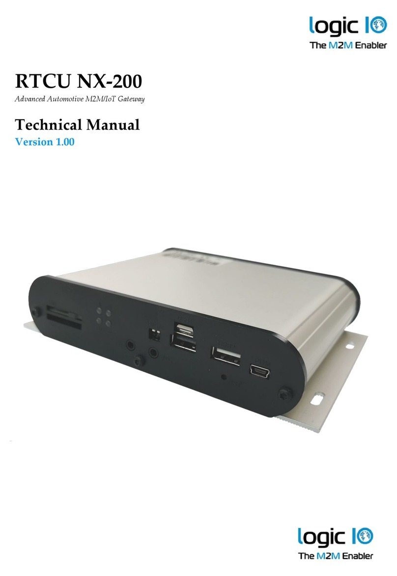
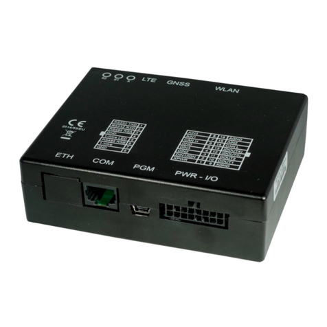
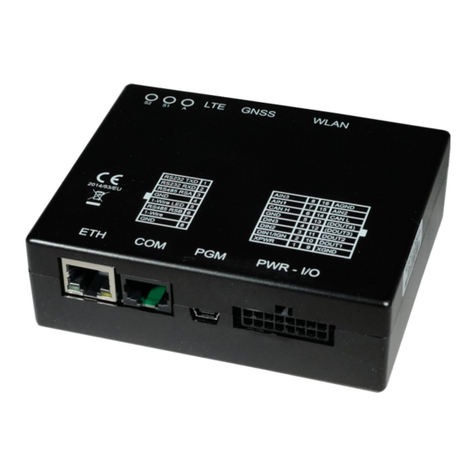
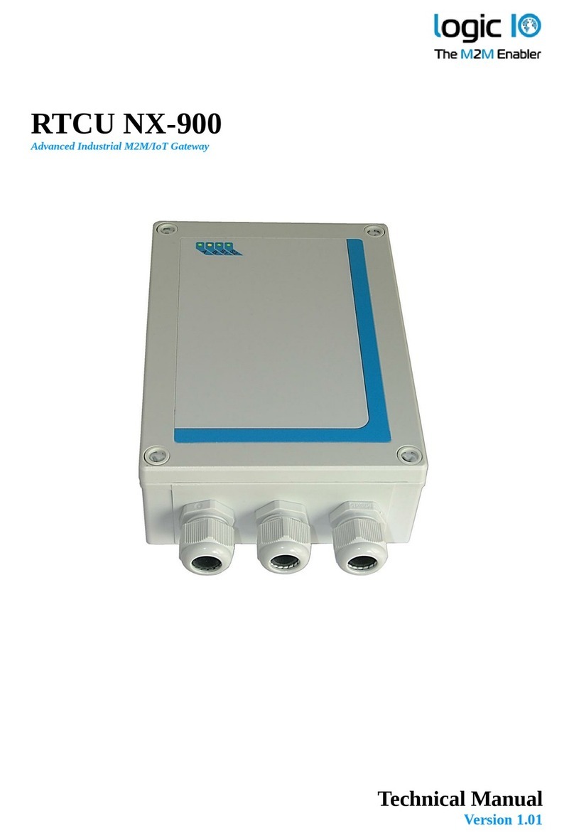
Logic IO RTCU NX-910 User manual

Technical Manual
Version 1.02
RTCU NX-910
Advanced Industrial M2M/IoT Gateway

RTCU NX-900 Technical Manual V1.02
Advanced M2M/IIoT Gateway
Logic IO ApS. Ph: (+45) 7625 0210
Holmboes Allé 14 Fax: (+45) 7625 0211
Denmark www.logicio.com
Introduction
The RTCU NX-910 is the most advanced industrial IoT Gateway product available on the market
today.
The device is based on the new NX32L (NX32 for Linux) architecture, which embraces many new
technologies and, at the same time, maintains full backward compatibility, which ensures already
implemented and tested NX32 applications can execute without changes.
The RTCU NX-910 is designed to meet the ever-increasing challenges on security, in that it offers
full TLS on all major protocols and includes a hardened protected execution environment with
dual-boot and automatic fallback and recovery.
The RTCU NX-910 device is an industrial-grade device that is designed from the ground up for
professional M2M / IoT applications with its strong on-board I/O capabilities and multiple com-
munication interfaces such as LTE, Ethernet, dual RS232, dual RS485, and 1-Wire.
The on-board I/O system can be expanded almost indefinitely and completely transparently by
adding Modbus I/O modules.
The RTCU NX-910 is, to a certain extent, fully software and hardware compatible with the RTCU
AX9 encore and the RTCU AX9 turbo.
The advanced power-management features on the RTCU NX-910 combined with the on-board
high-capacity Li-Ion battery allows the device to stay in a power-saving mode for a longer period
still being connected to the cellular network and capable of waking up on for example cellular ac-
tivity, change of digital inputs or a vibration sensor
This manual contains technical documentation on the installation and usage of the RTCU NX-910
device. For detailed information on the programming and software configuration of the product,
please refer to the RTCU IDE documentation.
For detailed information on the powerful RTCU M2M Platform, please refer to the
RTCU M2M Platform datasheet and the RTCU IDE documentation.

RTCU NX-900 Technical Manual V1.02
Advanced M2M/IIoT Gateway
Logic IO ApS. Ph: (+45) 7625 0210
Holmboes Allé 14 Fax: (+45) 7625 0211
Denmark www.logicio.com
Table of contents
Introduction.......................................................................................................................................... 2
Important Information..........................................................................................................................6
Migration from RTCU AX9 encore: ....................................................................................................9
Graphical overview:...........................................................................................................................10
Connections........................................................................................................................................ 11
Overview........................................................................................................................................ 11
Power supply..................................................................................................................................14
DC Supply.................................................................................................................................. 15
AC Supply.................................................................................................................................. 16
Digital I/O ......................................................................................................................................18
Relay outputs..............................................................................................................................18
Digital inputs / S0 inputs / wakeup (ignition) input...................................................................19
Analog I/O......................................................................................................................................21
Analog inputs .............................................................................................................................21
USB programming port..................................................................................................................23
RS232 communication ports (EIA/TIA-232 and V.28/V.24 compatible) ......................................23
RS232 port 1 ..............................................................................................................................23
RS232 port 2 ..............................................................................................................................23
RS485 communication ports (EIA/TIA-485-A compatible) ...........................................................24
RS485 port 1 ..............................................................................................................................25
RS485 port 2 ..............................................................................................................................25
1-Wire ............................................................................................................................................26
DC-Out........................................................................................................................................... 26
5V DC-Out ..................................................................................................................................... 26
12V/24V DC-Out ........................................................................................................................... 27
Ethernet ..........................................................................................................................................27
LED Indicators...................................................................................................................................28
User LED A and B .........................................................................................................................28
System LED S1 and S2..................................................................................................................29
Switches .............................................................................................................................................30
DIP-Switch..................................................................................................................................... 30
System switch (RST) ..................................................................................................................... 30
Internal Li-Ion battery........................................................................................................................ 31
LTE Cat. 1 Cellular Engine................................................................................................................32
High-speed link .................................................................................................................................. 32
Antennas............................................................................................................................................. 33
Cellular antenna ............................................................................................................................. 33
Internal SIM-Card reader ................................................................................................................... 34
Micro SD-Card reader........................................................................................................................ 34
Approved Micro SD cards .............................................................................................................35
Product Identification Label with Barcode ........................................................................................ 36
Power consumption............................................................................................................................37
Appendix A –Device configuration guide......................................................................................... 39
Appendix B –Installing the SIM card ............................................................................................... 41
Appendix C –Installing the Micro SD card ......................................................................................42
Appendix D –Open Source Disclaimer............................................................................................. 43
RTCU NX-910 Specifications ...........................................................................................................44

RTCU NX-900 Technical Manual V1.02
Advanced M2M/IIoT Gateway
Logic IO ApS. Ph: (+45) 7625 0210
Holmboes Allé 14 Fax: (+45) 7625 0211
Denmark www.logicio.com
Important Information
Thank you very much for using a product from Logic IO Aps. Our products are designed for
professional use, and therefore, this manual assumes technical knowledge and practice working
with such products.
This documentation does not entail any guarantee on the part of Logic IO Aps with respect to
technical processes described in the manual or any product characteristics set out in the manual.
We do not accept any liability for any printing errors or other inaccuracies in the manual, unless it
can be proven, that we are aware of such errors or inaccuracies, or that we are unaware of these as
a result of gross negligence and Logic IO Aps has failed to eliminate these errors or inaccuracies for
this reason.
This product is a complex and sensitive electronic product. Please act carefully and ensure
that only qualified personnel will handle and use the device. In the event of damage to the device
caused by failure to observe the information in this manual and on the device, Logic IO Aps shall
not be required to honor a warranty claim even during the warranty period and shall be exempted
from the statutory accident liability obligation. Any attempts to repair or modify the product also
voids all warranty claims.
Please contact Logic IO for any technical or commercial inquiries:
Logic IO Aps.
Holmboes Alle 14
8700 Horsens
Denmark
Phone: +45 76250210
Support: support@logicio.com
URL: www.logicio.com

RTCU NX-900 Technical Manual V1.02
Advanced M2M/IIoT Gateway
Logic IO ApS. Ph: (+45) 7625 0210
Holmboes Allé 14 Fax: (+45) 7625 0211
Denmark www.logicio.com
Technical Highlights
Platform:
➢Based on the RTCU M2M Platform.
➢NX32L (NX32 for Linux) execution architecture.
oRTCU IDE development tool.
oOperates under a full and highly optimized Linux variant.
oOpen and extendable with Platform SDK.
Hardware Core:
➢Cortex-A5 32-bit ARM processor operating at up-to 500 Mhz.
➢Hardware floating-point and DSP instructions.
➢128 MByte LP-DDR RAM.
➢512 MByte NAND Flash (filesystem).
➢16 MByte NOR flash (system boot).
➢8 MB Dataflash (persistent memory/datalogger).
➢128 KB SRAM with battery back-up (unlimited endurance).
➢Real-time clock with battery back-up.
Security:
➢Embedded firewall.
➢TLS/SSL support with full certificate management.
➢TLS/SSL support for all major TCP protocols, such as SMTP, MQTT, and sockets.
➢Hardware assisted encryption/authentication: AES-128, AES-192, AES-256, DES, TripleDES, HASH,
RND and RSA signature.
Wireless Communication:
➢LTE Cat. 1 Multi-Band Cellular Engine for EMEA.
➢Internal SIM-card reader and support for eSIM.
Wired Communication:
➢100 Mbps Ethernet LAN interface.
➢1-Wire bus for accessories such as ID-button reader, temperature sensors, etc.
➢2 x RS232 channels and 2 x RS485 channels.
I/O Interfaces:
➢2 x analog inputs with 0..10 volt / 0..20 mA with 12 bit precision.
➢5 x digital inputs and 4 x high-power relays.
➢Up to 4 digital inputs can be configured as IEC62053-31 Class A compliant.
➢Expandable I/O with standard Modbus modules.
Sensors:
➢Temperature sensor.

RTCU NX-900 Technical Manual V1.02
Advanced M2M/IIoT Gateway
Logic IO ApS. Ph: (+45) 7625 0210
Holmboes Allé 14 Fax: (+45) 7625 0211
Denmark www.logicio.com
User Interaction:
➢4 x bi-colour LED and 4 x position DIP-switch.
➢High-speed Mini-USB service-port connector.
Audio:
➢Fully digitized audio system.
➢Transfer, store, and play audio.
➢Digitized cellular audio.
➢DTMF support for Interactive Voice Response applications.
Storage:
➢Internal flash drive with up-to 512 MByte capacity.
➢Persistent memory and circular datalogger.
➢Standard SD-CARD reader.
Power and Battery:
➢Wide AC/DC power operating range from 100..260VAC / 8..36 VDC.
➢Onboard 2 Ah Li-Ion battery with intelligent charging.
➢5/12/24 Volt DC-out capability for powering external equipment.
Encapsulation:
➢Housed in a ruggedized plastic encapsulation with cable glands.
➢IP65 protected for outdoor usage.
Regulatory Approvals:
➢Radio Equipment Directive, RED 2014/53/EU.
➢EMC Directive, 2014/30/EU.
➢2011/65/EU RoHS Directive.

RTCU NX-900 Technical Manual V1.02
Advanced M2M/IIoT Gateway
Logic IO ApS. Ph: (+45) 7625 0210
Holmboes Allé 14 Fax: (+45) 7625 0211
Denmark www.logicio.com
Migration from RTCU AX9 encore:
There are the following differences between the RTCU AX9 encore and the RTCU NX-910:
Topic
AX9 encore
NX-910
Digital input –S0
Enabled by default
Disabled by default
Cable glands
Three PG11 + two optional PG9
Three M20
Cellular antenna
Internal + external
External
RS485 port 2
Shared with RS232 port 1, port=0
Dedicated port, port=3

RTCU NX-900 Technical Manual V1.02
Advanced M2M/IIoT Gateway
Logic IO ApS. Ph: (+45) 7625 0210
Holmboes Allé 14 Fax: (+45) 7625 0211
Denmark www.logicio.com
System LEDs
User LEDs
Graphical overview:
There are four user controlled LEDs and four system LEDs for simple information and status on
front of the RTCU NX-910:
The external antenna connectors are located at the top-side of the device, as shown below:

RTCU NX-900 Technical Manual V1.02
Advanced M2M/IIoT Gateway
Logic IO ApS. Ph: (+45) 7625 0210
Holmboes Allé 14 Fax: (+45) 7625 0211
Denmark www.logicio.com
Connections
Overview
Connections to external equipment are done via large and easy-to-use screw terminal blocks which
are accessible when the lid is removed. The placement of the terminals makes installation easy by
using the cable glands and thereby maintaining the IP-65 protection.
The RTCU NX-910 is delivered with three M20 cable glands.
A graphical overview of the device is shown below:
The stacked terminals contain connections for: analog and digital inputs/outputs, 12V/24 DC-
Output and DC power input.
The angled terminals contain connections for the communication interfaces: RS232 Port 1, RS232
Port 2, RS485 Port 1, RS485 Port 2, 1-Wire and the +5V DC-Output.
Cable glands
VAC terminals
Stacked terminals
AC/DC supply
Micro SD-card reader
Li-Ion battery
LEDs
Ethernet connector
USB Service port
Configuration jumpers
Angled terminals
DIP Switches
SIM-Card reader
Antenna connector

RTCU NX-900 Technical Manual V1.02
Advanced M2M/IIoT Gateway
Logic IO ApS. Ph: (+45) 7625 0210
Holmboes Allé 14 Fax: (+45) 7625 0211
Denmark www.logicio.com
Stacked terminal overview
Terminal Name
TOP row BOT row
Description
R1A
Contact set for relay output 1.
R1B
R2A
Contact set for relay output 2.
R2B
R3A
Contact set for relay output 3.
R3B
R4A
Contact set for relay output 4.
R4B
N.C
Not connected.
N.C
Not connected.
DCIN
DC power supply, positive (+) connection.
XGND
DC power ground, negative (-) connection.
DCOUT
12V / 500mA or 24V / 250mA DC output for external equipment.
GND
Signal ground.
DI1
Digital input 1 / S0 input 1.
DI2
Digital input 2 / S0 input 2.
DI3
Digital input 3 / S0 input 3.
DI4
Digital input 4 / S0 input 4.
DI5
Digital input 5 / Wakeup (ignition) input.
GND
Signal ground.
AI1
Analog input 1.
AI2
Analog input 2.
AGND
Analog ground.
Angled terminal front row overview
Terminal Name
Description
SER1_TXD
Transmit data from serial port 1, RS232 compatible.
SER1_RXD
Receive data for serial port 1, RS232 compatible.
DEV_DET
Reserved for accessories.
SGND
Signal ground.
1Wire
1-Wire bus.
1Wire-LED
1-Wire ID-Button LED output.
SGND
Signal ground.
RS485_2+
RS485 non-inverting signal for RS485 port 2.
RS485_2-
RS485 inverting signal for RS485 port 2.

RTCU NX-900 Technical Manual V1.02
Advanced M2M/IIoT Gateway
Logic IO ApS. Ph: (+45) 7625 0210
Holmboes Allé 14 Fax: (+45) 7625 0211
Denmark www.logicio.com
Angled terminal back row overview
Terminal Name
Description
SER2_TXD
Transmit data from serial port 2, RS232 compatible.
SER2_RXD
Receive data for serial port 2, RS232 compatible.
SER2_CTS
Clear-To-Send for serial port 2, RS232 compatible.
SER2_RTS
Request-To-Send for serial port 2, RS232 compatible.
SGND
Signal ground.
DCOUT5
+5V / 300mA DC output for external equipment.
RS485_1+
RS485 non-inverting signal for RS485 port 1.
RS485_1-
RS485 inverting signal for RS485 port 1.
SGND
Signal ground.
VAC terminal overview
Terminal Name
Description
N
100-260VAC (50/60Hz) Null input.
(internally tied together)
N
P
100-260VAC (50/60Hz) Phase input.
(internally tied together)
P
Protective earth terminal for the AC power.
(internally tied together)
Connector Mini USB-B
The USB port is for programming and communication with the RTCU IDE (RACP compliant
application). A standard USB cable with a connector length of 10mm on the USB-B end can be used
between the device and the PC
Connector Ethernet
This is a standard 10Base-T/100Base-TX IEEE 802.3 compliant Ethernet connector. Please use an
appropriate connector and cable, such as a standard CAT-5 twisted pair patch cable

RTCU NX-900 Technical Manual V1.02
Advanced M2M/IIoT Gateway
Logic IO ApS. Ph: (+45) 7625 0210
Holmboes Allé 14 Fax: (+45) 7625 0211
Denmark www.logicio.com
Power supply
The RTCU NX-910 device can be supplied with either 100-260VAC (50/60Hz) or 8-36VDC or both
supply types simultaneously.
The RTCU NX-910 also contains an internal high capacity backup battery, which will supply the
RTCU if the external power should fail or be disconnected. By default, the RTCU NX-910 is
powered down when a power fail occur. This setting, however, can be changed. Please consult the
RTCU-IDE on-line help for more information.
When the wakeup/ignition input is activated with a logical high, the RTCU NX-910 device will
wake up if it was in power down mode.
There are five different ground labels: External Ground (XGND), Signal Ground (SGND), Digital
Ground (GND), Analog Ground (AGND) and AC power ground (PE). The signal, digital and
analog grounds are filtered from the power ground. External ground must only be used as a DC
power supply return path. The AC ground is used in order to have a common reference between
external AC powered system and the internal system. The digital ground is used as ground
reference for digital I/O’s, signal ground is used as ground reference for serial interfaces, and the
analog ground is used as a low noise analog ground reference for the analog inputs.
Dual Supply Note:
The RTCU NX-910 can be supplied with both VAC and VDC at the same time. The device will run
on the VAC supply if the VDC supply voltage is < +24VDC. If the VDC supply voltage is higher it
will run on the VDC supply.
Please refer to the RTCU on-line help for information on how to check the supply type from within
an application.

RTCU NX-900 Technical Manual V1.02
Advanced M2M/IIoT Gateway
Logic IO ApS. Ph: (+45) 7625 0210
Holmboes Allé 14 Fax: (+45) 7625 0211
Denmark www.logicio.com
DC Supply
The RTCU NX-910 can be supplied with 8-36VDC from an external DC power source. Positive
power is applied to the DCIN pin and ground is connected to the XGND pin.
The DC supply of the NX-910 is protected against wrong polarity. If a system ground is connected
to either SGND or AGND, a wrong polarity on the supply lines will destroy the internal GND
connection.
Please Note:
➢Minimum 15VDC supply is necessary for 0-10V analog output and 12V DC out.
➢Minimum 16VDC supply is necessary for digital inputs 1-4 to work as S0 compliant inputs.
VDC Supply terminals
Terminal Name
Description
DCIN
Power supply, positive (+) connection.
XGND
Power ground, negative (-) connection.

RTCU NX-900 Technical Manual V1.02
Advanced M2M/IIoT Gateway
Logic IO ApS. Ph: (+45) 7625 0210
Holmboes Allé 14 Fax: (+45) 7625 0211
Denmark www.logicio.com
VAC terminal
Protective Earth
AC Supply
The RTCU NX-910 device can be supplied with 100-265VAC (50/60Hz) from a standard wall plug
or any other high-voltage VAC power rail.
The AC supply of the RTCU NX-910 is a highly efficient switch mode power supply and the AC
input is protected internally with a 2A/250V Fast Acting non-replaceable fuse.
AC power must be applied between the Nand Pon the designated screw terminals.
Protective Earth (PE) connection terminals are labeled with the sign .
VAC Supply terminals
Terminal Name
Description
N
100-260 VAC (50/60Hz) Null input
(internally tied together)
N
P
100-260 VAC (50/60Hz) Phase input
(internally tied together)
P
Protective Earth connector
Please Note:
The two pairs of Nand Pterminals, and the terminal marked with are internally connected.
There is high voltage on certain areas of the PCB (Printed Circuit Board) when supplied with AC
mains. There is a risk of electrical hazard therefore avoid touching the PCB and the components
during operation.
Be aware that the supply filter contains capacitors that may remain charged after
the equipment is disconnected from the supply. Although the stored energy is
within the approved safety requirements, a slight shock may be felt if the plug pins
are touched immediately after removal.
Refer all servicing and handling to qualified personnel.
Please note:
The DC ground of the NX-910 is isolated from the AC ground because of the nature of AC-to-DC
converting. As these two grounds are not tied together anywhere in the NX-910, the DC ground
may appear as "floating ground" to the outside if the NX-910 ground is not connected to the same

RTCU NX-900 Technical Manual V1.02
Advanced M2M/IIoT Gateway
Logic IO ApS. Ph: (+45) 7625 0210
Holmboes Allé 14 Fax: (+45) 7625 0211
Denmark www.logicio.com
reference as the outside and a potential difference may occur. This difference can interrupt the
behavior of the device and in worst case damage that part of the device. This must be taken in
consideration when the NX-910 devices are supplied with AC supply. When the NX-910 is
supplied with DC voltage, this "potential difference" issue may not be observed as the DC power
supply usually has the same potential as the rest of the system.
In order to avoid this, the Earth connection on the AC supply rail can be connected to the terminal
that has been marked with the symbol .
For circuitry in situations where significant Earth ground currents can flow isolating the DC
ground from Earth grounds may be desired. In this case the DC ground may be tied together with
the Earth ground through a high impedance connection.
For the best EMI performance/ESD immunity in combination with a common reference it is
recommended to connect DC ground and Earth together with a low-inductance connection.

RTCU NX-900 Technical Manual V1.02
Advanced M2M/IIoT Gateway
Logic IO ApS. Ph: (+45) 7625 0210
Holmboes Allé 14 Fax: (+45) 7625 0211
Denmark www.logicio.com
Digital I/O
The RTCU NX-910 has five digital inputs and four normally-open relay outputs.
The outputs are high performance relays with good current handling capabilities.
Digital input 1-4 have multiple operating modes. Please refer to the digital input section for
additional information.
Relay outputs
The digital outputs control four relays and they act like normally-open contacts, where one side
must be connected to a source that needs switching and the other contact terminal is the output.
The source can be either VAC or VDC but the maximum switchable voltage and current must not
be exceeded. Please refer to specification page.
There are no internal connections to the relay outputs and a source must therefore always be
connected to one of the relay terminals for the output to work.
The RTCU NX-910 device offers a very advanced power management which makes it possible to
have one or more outputs enabled while the RTCU is in low-power mode. Please consult the
RTCU IDE on-line help for more information.
Relay output terminals
Terminal Name
Description
R1A
R1B
Contact set for relay output 1.
R2A
R2B
Contact set for relay output 2.
R3A
R3B
Contact set for relay output 3.
R4A
R4B
Contact set for relay output 4.
Load noise
If highly inductive loads (such as high-power contactors) are connected to the relays, it may in
certain cases be necessary to externally connect a clamping diode parallel with each inductive DC
load or connect an RC snubber circuit parallel with each inductive AC load.
For DC applications Vishay UF5405-E3/54 or similar is recommended and for AC applications
AMPOHM FE-SP-HDR23-47/100 (47nF/100 ohm) or similar is recommended.

RTCU NX-900 Technical Manual V1.02
Advanced M2M/IIoT Gateway
Logic IO ApS. Ph: (+45) 7625 0210
Holmboes Allé 14 Fax: (+45) 7625 0211
Denmark www.logicio.com
Digital inputs / S0 inputs / wakeup (ignition) input
The five digital inputs are all low-pass filtered (16kHz) and transient-protected. To activate the
inputs, connect a positive voltage between the corresponding input (DINx) and SGND.
Digital input 1-4 can be configured individually as S0 input (IEC62053-31, Class A) and DIN5 can
work as wakeup (ignition) input.
By default, the digital inputs are configured as normal inputs. For placement and configuration of
the hardware jumpers inside the device, please refer to the configuration guide in Appendix A.
S0 compliant inputs (IEC62053-31, Class A compatible)
In S0 configuration the relevant RTCU NX-910 input will act as a ‘pulse input device’, and a
current is supplied into the input connector so that a simple switch between SGND and the
appropriate input will activate it. This is used in most electricity metering equipment.
Please note: The NX-910 device must be supplied with a minimum of 16 VDC or AC power for the
S0 mode to work correctly.
S0 is disabled by default and must be enabled by the application.

RTCU NX-900 Technical Manual V1.02
Advanced M2M/IIoT Gateway
Logic IO ApS. Ph: (+45) 7625 0210
Holmboes Allé 14 Fax: (+45) 7625 0211
Denmark www.logicio.com
Wakeup (ignition) input
The DI5 / wakeup (ignition) input is a special input as it also functions as the ignition. If the input is
activated with a logical high when the RTCU NX-910 is in power down mode, it will wake the
device. A power apply will also wake the device up if it is in power-down mode.
In the other power saving modes, all the inputs and power apply/fail can be used to wake the
device with individually configured falling- or rising edge detection. Please consult the RTCU IDE
on-line help for more information.
The inputs are de-bounced with a period between 1-2 ms when used as a digital input therefore
any logical level applied to this input must be longer than 2 ms to be valid.
For placement and configuration of the hardware jumpers inside the device, please refer to the
device configuration guide in Appendix A.
Digital input terminals
Terminal Name
Description
Jumper Setting
DI1
Digital input 1 or
S0 input 1
JPDI1 in position N(default)
JPDI1 in position S
DI2
Digital input 2 or
S0 input 2
JPDI2 in position N(default)
JPDI2 in position S
DI3
Digital input 3 or
S0 input 3
JPDI3 in position N(default)
JPDI3 in position S
DI4
Digital input 4 or
S0 input 4
JPDI4 in position N(default)
JPDI4 in position S
DI5
Digital input 5 and
Wakeup (ignition) input
GND
Digital Ground
Specification for each digital input
Min.
Typ.
Max.
Unit
Logic “High”
8
12
40
VDC
Protected against transients and low-
pass filtered
@ 12V
@ 12V
Logic “Low”
-5
-
3
VDC
Bandwidth (normal)
-
12
-
kHz
Bandwidth (s0)
-
4
-
kHz
Input impedance
-
13.8
-
kΩ
Table of contents
Other Logic IO Gateway manuals
Popular Gateway manuals by other brands

Elcon
Elcon ELCONnect next BIG 101 Series user manual

ZyXEL Communications
ZyXEL Communications P-870HW-51A V2 quick start guide

RAK
RAK WisGate Edge Max quick start guide

Star2Star
Star2Star Polycom OBi312 installation guide

NetComm
NetComm NetComm Gateway Series user guide

Portech
Portech MV-3732 user manual