Operation and Maintenance Instruction LNK-OM-NS Sidelight & Sternlight /A1
5
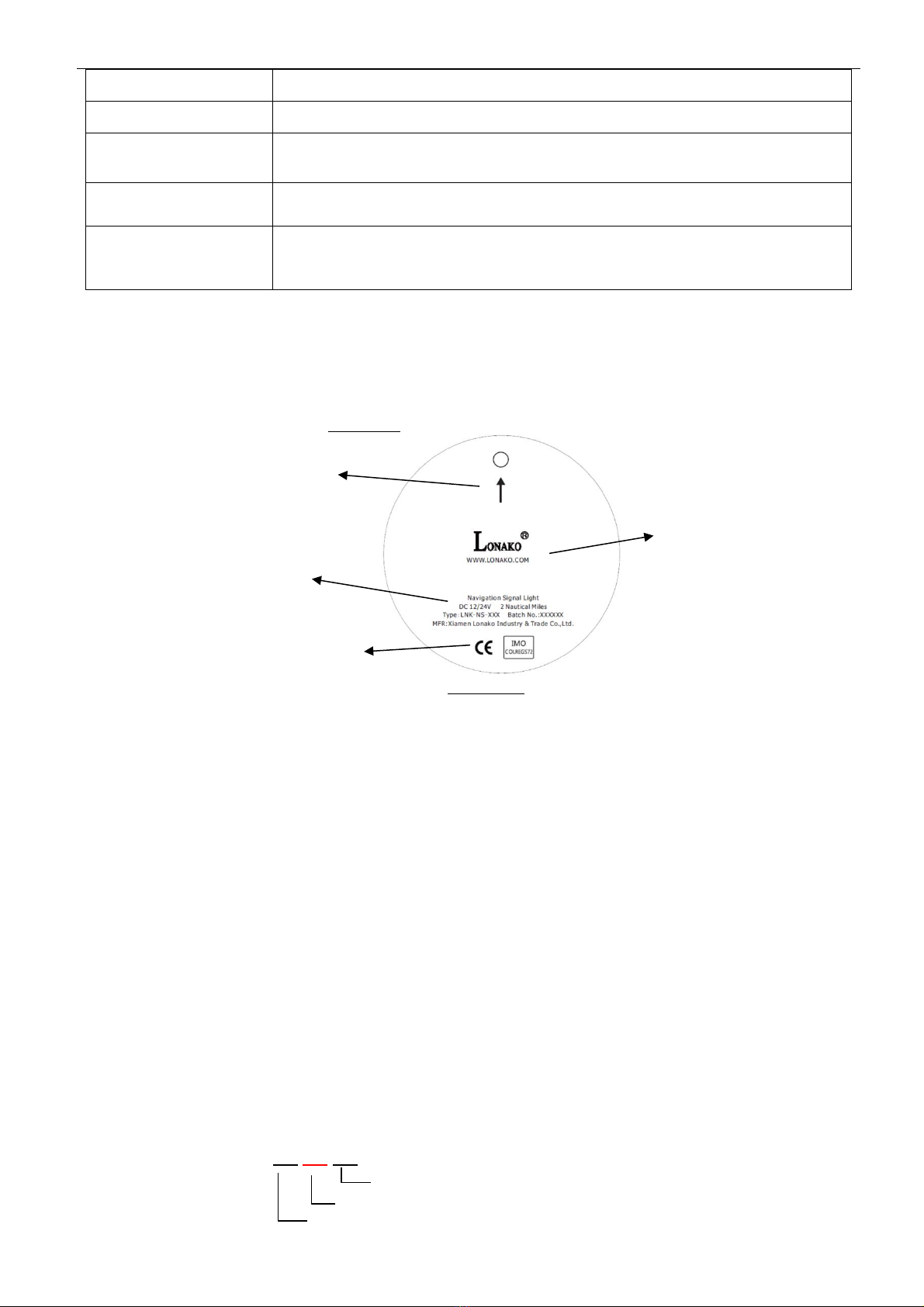
①The two digits in the front represent the design version, example: A1, A2, A3……
when the 2nd number increase to 9, the later version shall change the letter, example
B1, B2, B3…… and so on;
②The two digits in the front represent the year of manufacturing, example: 20
represents year 2020;
③The last two digits represent the manufacturing batch of per year. Example: “06”
represents the 6th manufacturing batch of the current year.
SECTION ⅢINSTALLATION INSTRUCTIONS
3.1 Installation Limitation
LNK-NS Deck mount series sidelight & sternlight suitable for all types of vessels with a length <
20 meters. They are controlled through cabin controlling panel, and showing unbroken light
signal to indicate the different status of the vessel.
3.2 Installation Instruction
3.2.1 LNK-NS Deck mount series sidelight & sternlight should be installed on the according
position on the deck, and ensure that the light is visible from correct direction and unobstructed.
Each type`s mounting position as below:
1)LNK-NS-R should be installed on the deck of port side close to the edge horizontally, and so
fixed as to show the light right ahead to 22.5°abaft the beam on port side.
2) LNK-NS-G should be installed on the deck of starboard side close to the edge horizontally,
and so fixed as to show the light right ahead to 22.5°abaft the beam on starboard side.
3) LNK-NS-RG Bi-color light should be installed on the deck of the fore and aft center line of the
vessel horizontally, as nearly as practicable at the prow of vessel.
4) LNK-NS-W Stern light should be installed on the deck of the fore and aft center line of the
vessel horizontally, as nearly as practicable at the stern.
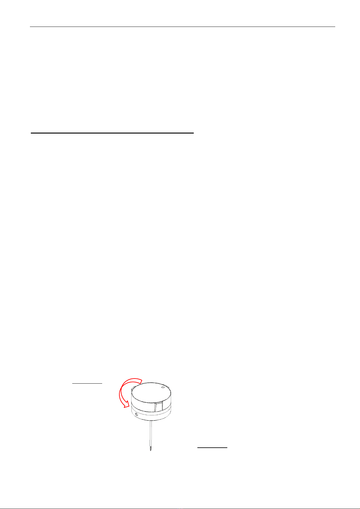
3.2.2 Before installation, remove the screw on the product mounting base, hold the base with
one hand, grasp the main light body with the other hand, twist the main light body in a counter
clockwise direction, the light should be open. Be aware there is a M4 nut in the groove of the
base.( Figure 3-1)
Figure 3-1
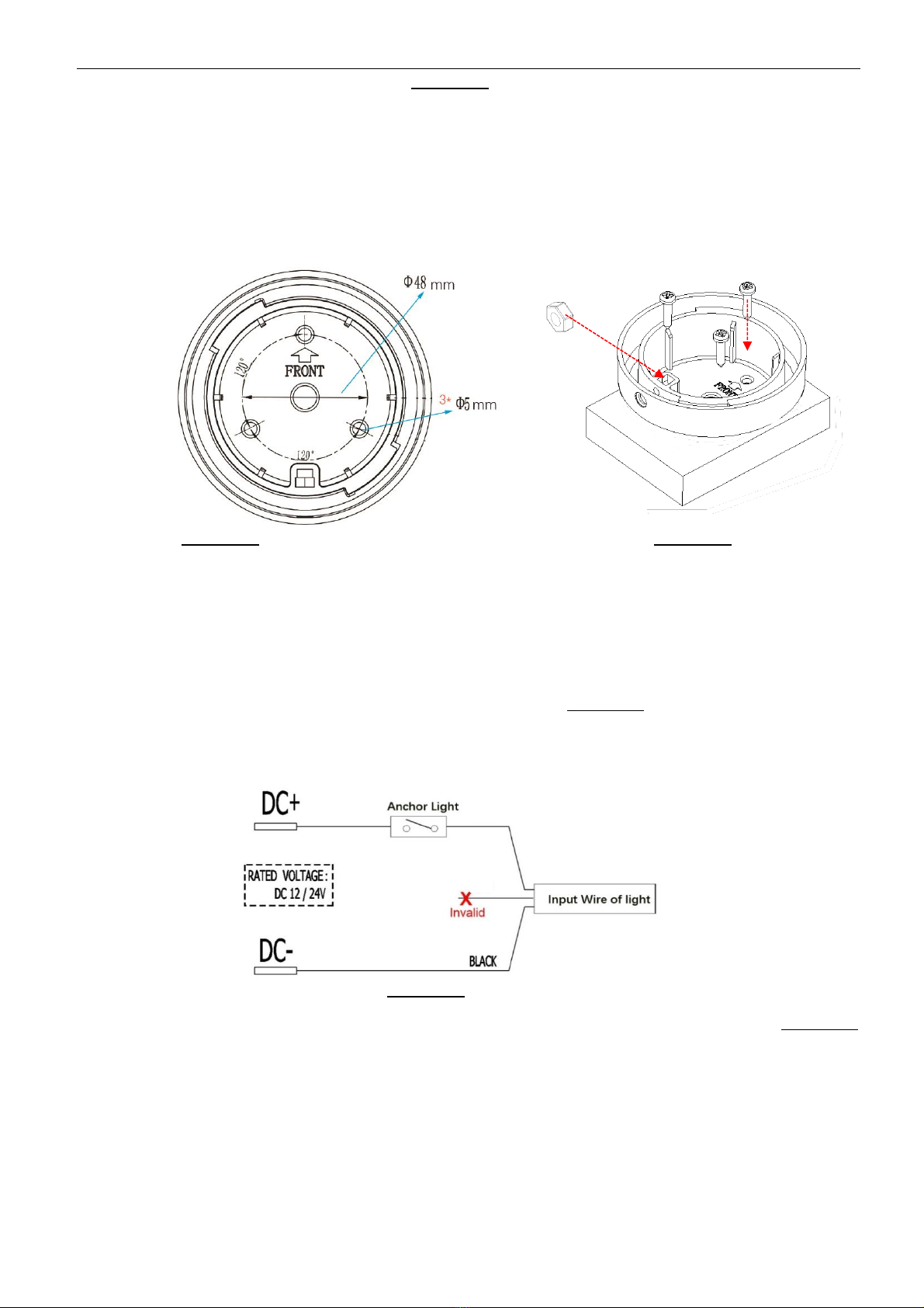
3.2.3 Drill three fixing holes at the selected installation position according to the drawing of screw