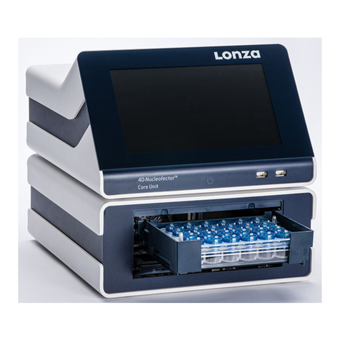
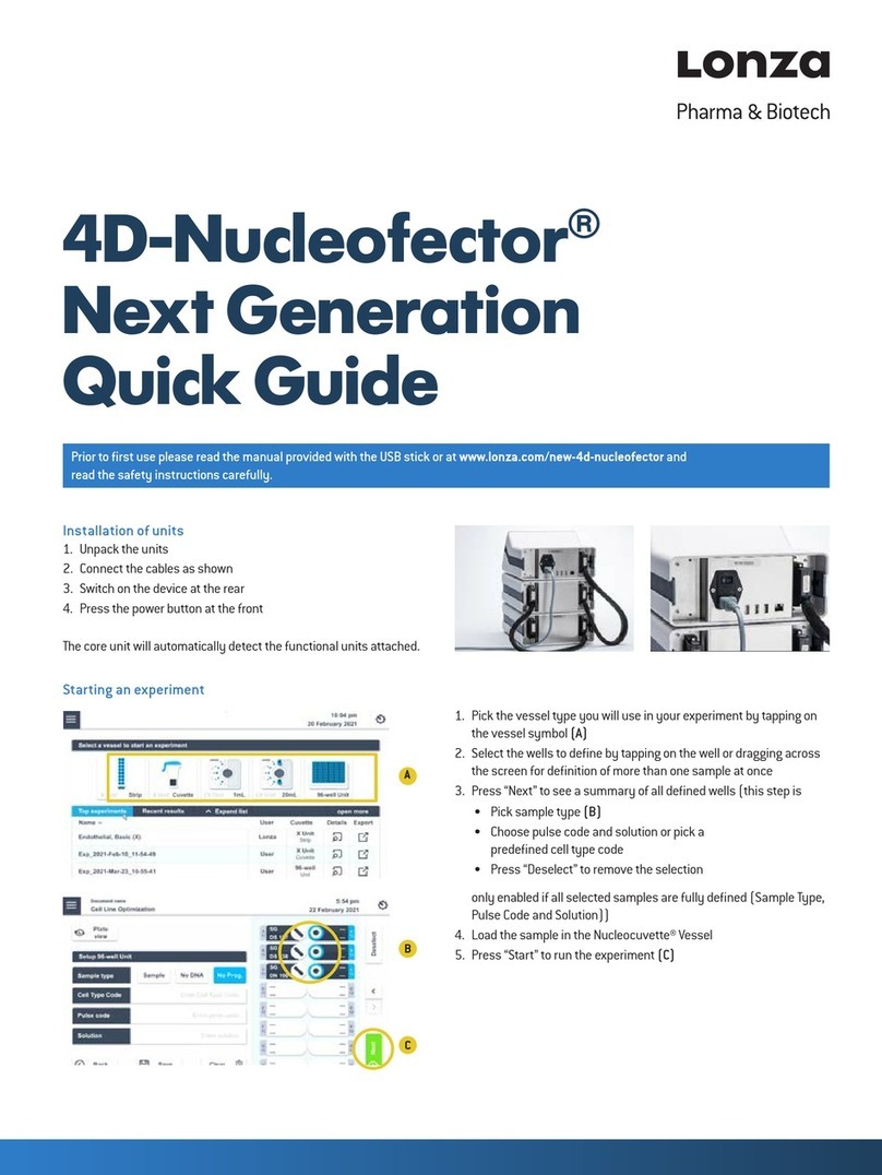
Lonza 4D-Nucleofector User manual

Bioscience Solutions
4D-Nucleofector™ System Manual
For Research Use Only

2 Bioscience Solutions – 4D-Nucleofector™ Manual
The purchase of the 4D-Nucleofector™ System conveys to
the buyer the non-transferable right to use the system as
well as Lonza’s proprietary Nucleofector™ Technology for
research conducted by the buyer (whether the buyer is an
academic or for-prot entity). For further details about the
license please refer to chapter 5.

4D-Nucleofector™ Manual – Bioscience Solutions 3
Content
1 The Nucleofector™ Technology 4
2 Operating Instructions 6
2.1 Restrictions 6
2.2 Maintenance 6
2.3 Safety Instructions – Please Read Carefully 7
2.4 Waste Disposal 7
2.5 4D-Nucleofector™ System Components 8
2.6 Set-up Instructions 9
2.7 General Use Instructions 10
2.7.1 Turning on the 4D-Nucleofector™ System 10
2.7.2 Adjusting the Position of the Touch Screen 10
2.7.3 Operating Software 11
2.7.4 Turning o the 4D-Nucleofector™ System 11
2.8 General Instructions for Running a Nucleofection Experiment 12
2.8.1 Overview 12
2.8.2 Unit and Vessel Selection 13
2.8.3 Experiment Parameters - Overview 13
2.8.4 Using a Predened Experiment 14
2.9 4D-Nucleofector™ X Unit 15
2.9.1 Dening a New Experiment 15
2.9.2 Loading Samples 16
2.9.3 Running the Experiment 17
2.10 4D-Nucleofector™ Y Unit 18
2.10.1 Dening a New Experiment 18
2.10.2 Loading Samples 19
2.10.3 Running the Experiment 19
2.11 4D-Nucleofector™ LV Unit 20
2.11.1 Using the 1 mL Nucleocuvette™ Cartridge
(Fixed Volume) 21
2.11.1.1 Dening a New Experiment 21
2.11.1.2 Loading Samples 22
2.11.1.3 Running the Experiment 22
2.11.2 Using the LV Nucleocuvette™ Cartridge
(Scalable Volume) 23
2.11.2.1 Mounting an LV Nucleocuvette™
Cartridge 23
2.11.2.2 Dening a New Experiment 25
2.11.2.3 Running the Experiment 27
2.12 Additional Settings and Options 28
2.12.1 Experiments 28
2.12.2 Results 29
2.12.3 Custom Programs 29
2.12.4 Synchronize 30
2.12.5 Cleaning the Nucleofection Vessel Tray
(X or Y Unit) 30
2.12.6 Lonza Programs 30
2.12.7 Firmware Update 30
2.13 PC Editor Software 31
2.14 96-well Shuttle™ Mode 33
3 Troubleshooting 33
3.1 Suboptimal Transfection Results 33
3.2 Rescue of Samples (X and Y Unit) 34
4 Error Codes of the
4D-Nucleofector™ System 35
4.1 Arc Discharge Correction 35
5 Purchaser Notication 37
6 Technical Specications 38

4 Bioscience Solutions – 4D-Nucleofector™ Manual
1 The Nucleofector™ Technology
Since its introduction in 2001, Nucleofector™ Technology has transformed
transfection. Nucleofection has proven to be a reliable and reproducible
easy-to-use technology, suited to a wide variety of applications. An ever
increasing number of publications in a wide range of research areas reect
how Nucleofector™ Technology is driving research in numerous cell types
and applications. Nucleofector™ Technology provides an answer to almost
every transfection challenge.
How it Works
Nucleofector™ Technology is based on two unique components, the
Nucleofector™ System that delivers the specically optimized electrical
parameters and Nucleofector™ Kits, which contain specic Nucleofector™
Solutions. As part of Nucleofector™ Technology, Lonza provides cell-type
specic optimized protocols for many dierent cell lines and primary cells.
Transfection of Any Cell
With over 160 protocols optimized by Lonza’s R&D Team for cell lines and
primary cells and more than 680 entries in the online Cell Transfection
Database, Nucleofector™ Technology is the transfection method of choice
for dicult-to-transfect cell types. Moreover, Nucleofection is the only
electroporation-based technology allowing reliable transfection of
adherent cells and cells in suspension.
Transfection of Any Substrate
Nucleofector™ Technology oers high exibility within applications,
since the same transfection parameters apply for almost all substrates.
DNA vectors, RNA duplexes, and peptides can be transfected using our
sophisticated transfection protocols. This makes Nucleofection an ideal
tool for providing answers to scientic questions in over-expression
studies, gene silencing approaches, protein expression, generation of
stable clones and many more applications besides.
Moving Transfection into the Forth Dimension
At Lonza, we believe that listening to our customers is the best way
to develop innovative products that meet your needs. In line with this
customer-oriented spirit, the 4D-Nucleofector™ System was developed
to oer advanced performance, exibility and convenience. The system
is controlled by intuitive software on an up-to-date touch screen user
interface. Its modular architecture allows seamless expansion of the
system for new applications.
Experience the Advanced Nucleofector™ Platform:
–
A novel conductive polymer based cuvette system completely free
of toxic metal ions
– Transfection of dierent cell numbers using the same conditions
– Nucleofection of cells in adherence
–
Closed, scalable transfection of larger cell numbers in the range of
1x10⁷to 1x10⁹
www.lonza.com/cell-database

6 Bioscience Solutions – 4D-Nucleofector™ Manual
2.1 Restrictions
Medical use restrictions
Nucleofector™ Technology is intended for research and investigational
use by professionals only. Please note that Lonza’s Nucleofector™
Technology is not intended to be used for diagnostic purposes, for testing
or treatment in humans.
License statement
Lonza is holder of various patents, patent applications, copyrights
and technical and scientic experience with respect to Nucleofector™
Technology. Use of Lonza’s Nucleofector™ Technology and /or related
software requires a license from Lonza.
Purchasers are granted a non-exclusive, non-transferable license
for a limited use of Lonza’s Nucleofector™ Technology and related
software for research and development purposes, the terms of which
are disclosed in detail in chapter 5. Certain commercial application is
allowed under Lonza’s license for for-prot-entities, as set forth in the
license.
For license information contact Lonza Cologne GmbH:
Phone +32 87 321 611
E-mail ip.cologne@lonza.com
2.2 Maintenance
The 4D-Nucleofector™ System requires minimal maintenance for reliable
operation. Unplug the power supply before cleaning and disinfecting the
case. Use a damp cloth to wipe down the outer case with water or 70–80%
ethanol. Do not use any aerosols for cleaning. Avoid wetting the cuvette
holder within the cuvette tray and the connectors located on the rear of
the system.
The 4D-Nucleofector™ System is designed for use under a sterile hood
either with or without a UV radiation source. Prolonged exposure of the
outer casing to UV light may lead to discoloration but not functional
impairment of the Nucleofector™ System. However, the system should
be removed from the hood during extended UV irradiation.
The 4D-Nucleofector™ System is protected by two main fuses. Both are
inside a receptacle incorporated in the power socket of the Core Unit
(see gure 2.0). Blown fuses can easily be replaced. Disconnect the
4D-Nucleofector™ System from the power supply and insert a small at
screwdriver into the slot on top of the power plug housing to lever it open.
The fuse receptacles (each marked with an arrow) are then also levered
open using the screwdriver.
Figure 2.0: Opened fuse receptacles
2 Operating Instructions
The 4D-Nucleofector™ System will not function unless both the left and right receptacle
contain intact fuses. Blown fuses can usually be identied by molten broken wires inside
the glass tube. Only use T2.5A, L fuses to replace blown fuses.

4D-Nucleofector™ Manual – Bioscience Solutions 7
2.3 Safety Instructions –
Please Read Carefully
This symbol means that there is a risk of electric shock. An electric shock
could cause death or personal injury.
The 4D-Nucleofector™ System has been certied by international
safety standards and is safe to use when operated in accordance
with this manual.
This system is designed to deliver variable high voltage electrical impulses
for the purpose of introducing substrates into eukaryotic cells.
These electrical impulses can be deadly!
Therefore, use this system with care and take the following precautions:
–
Only use the system once you have read the 4D-Nucleofector™ Manual.
The manual should be accessible for all users. Make sure that each
potential user reads it.
–
Do not open the system. The system does not contain user-serviceable
parts. Under no circumstances should circuit components be interfered
with, as they can deliver an electric shock even when system is not
in operation.
– Do not alter the system in any manner.
–
Do not obstruct the movement of the drawer holding the Nucleofection
vessels or culture plates.
–
Do not plug any non-Lonza-certied connectors into the external high
voltage electrode sockets at the rear side of the 4D-Nucleofector™
System. They are designed to connect certied add-on systems to the
4D-Nucleofector™ System, e.g., the 96-well Shuttle™ Device.
– Only use the system when it is set on top of a safe, leveled and stable
table or bench.
– Set up the system in such a way that easy removal of the power cord
is possible at any time.
– Do not expose the system to a humid environment.
– The system must not be exposed to direct sunlight nor be placed in
a hot environment.
– The system is not approved for use in re- or explosion-endangered
areas, nor for use with inammable or explosive media.
– Take precautions against severe impacts and vibration while moving
and transporting the 4D-Nucleofector™ System.
–
Only use the system with Lonza-certied Nucleofector™ Solutions
and Lonza-certied Nucleofection vessels (100 µL Nucleocuvette™
Vessel or 20 µL Nucleocuvette™ Strip for X Unit; 1 mL or LV
Nucleocuvette™ Cartridge for LV Unit; 24-well Dipping Electrode Array
for Y Unit). Using consumables from any other source than Lonza will
preclude all warranty and liability claims.
–
Do not alter the setup of the pre-assembled LV Nucleocuvette™
Cartridge.
–
Standard Nucleofector™ Solutions are not compatible with the
4D-Nucleofector™ System.
– Never unplug high voltage cable while system is running.
–
Unpack the Nucleocuvette™ Vessels or 24-well Dipping Electrode
Arrays immediately before the experiment. Make sure that the outer
contact areas are dry.
– Safety may be compromised if any uid has been spilled in the close
vicinity of the 4D-Nucleofector™ System. Ensure that no uid is in
contact with or has entered the system.
–
System safety may be compromised if any uid enters the system. To
ensure that the system is safe to use, contact Lonza Scientic Support
for advice on actions or precautions that should be taken.
– Do not insert or place foreign objects in the electrical drawers of the
4D-Nucleofector™ System.
–
Safety may be compromised if any foreign object has entered the
4D-Nucleofector™ System. To ensure that the system is safe to use,
contact Lonza Scientic Support for advice on actions or precautions
that should be taken.
–
If the 4D-Nucleofector™ System has been damaged, ensure that the
system can not be used by any personnel and contact Lonza Scientic
Support for assistance.
– All service shall be performed by Lonza authorized personnel only.
–
Handling of system parts that may be contaminated with sample
should always be performed using protective gloves and any disposal
of such parts must be according to federal, state or local procedures for
clinical waste handling and disposal. Use secure leakproof containers
and avoid unprotected handling of such parts.
Lonza disclaims all warranties and shall in no event be liable for any kind
of damages caused by or arising out of any operation or use in violation
with the above safety and handling instructions.
2.4 Waste Disposal
Disposal of used consumables from Nucleofector™ Kits
Dispose used cuvettes, pipettes and Nucleofector™ Solutions in a biohazard
container. Refer to your local waste management organization and to the
relevant laboratory safety instructions for proper disposal practices.
2

8 Bioscience Solutions – 4D-Nucleofector™ Manual
2.5 4D-Nucleofector™ System
Components
By denition the 4D-Nucleofector™ System is a modular system oering
maximum exibility. Therefore, a complete system may vary in the number
and type of components it contains. Furthermore, a system may consist
of minor model variants of the units. These variants can be discriminated
by their part codes and serial numbers (table 2.1).
Table 2.1: Overview of model variants
Model Variant A Variant B
Years 2010 – 2013 2013 – Now
Part codes Core Unit: AAF-1001B
X Unit: AAF-1001X
Y Unit: AAF-1001Y
Core Unit: AAF-1002B
X Unit: AAF-1002X
Y Unit: AAF-1002Y
LV Unit: AAF-1002L
Serial numbers Core Unit: 5**B****
X Unit: 5**X****
Y Unit: 5**Y****
Core Unit: 8**B****
X Unit: 8**X****
Y Unit: 8**Y****
LV Unit: 9**LV***
Unit arrangement horizontal or vertical
(via demountable side panels)
vertical only
(xed side panels)
Core Unit – display
frame
silver blue
X/Y Unit – sample rescue
(also see 3.2)
using wheel accessible after
removal of side panel
via screw behind termination
plug
A typical 4D-Nucleofector™ System includes:
1. One 4D-Nucleofector™ Core Unit
2. At least one functional unit
– X Unit: comprising two retainers for 100 μL Nucleocuvette™ Vessels
and one retainer for 16-well Nucleocuvette™ Strips
– Y Unit: enabling transfection of cells in adherence using a 24-well
Dipping Electrode Array
– LV Unit: for large volume transfection of up to 109cells
3. Power cord
4. Interface cable for high voltage and data connection (plus termination
plug cap, not shown)
Figure 2.1: 4D-Nucleofector™ System before assembly
12
34
5. Touch screen (graphical user interface of the system)
6. Operation LED
7. USB port (for USB stick)
8. X Unit with tray holding retainers for two 100 μL Nucleocuvette™
Vessel and one 16-well Nucleocuvette™ Strip
9. Y Unit with tray holding 24-well Dipping Electrode Array for adherent
transfection
10. LV Unit with slot for 1 mL or LV Nucleocuvette™ Cartridge
Figure 2.2: 4D-Nucleofector™ System comprising Core, X and Y Unit (A) or Core, X and
LV Unit (B)
8
6
7
5
9
10
AB

4D-Nucleofector™ Manual – Bioscience Solutions 9
11. Power cord socket with main power switch and fuses
12. USB port (for PC connection)
13. Serial port for shuttle connection
14. Lonza interface outlet port to connect functional units
15. Lonza interface inlet port to connect functional units
16. Lonza interface inlet port of last functional unit with
termination plug
17. HV outlets for the 96-well Shuttle™ Add-on
Figure 2.3: 4D-Nucleofector™ System comprising Core, X and Y Unit (rear view)
14
13
15
11
14
12
17
The 4D-Nucleofector™ System comes with default programs and includes
a USB port at the front for software updates.
16
2.6 Set-up Instructions
1. Unpack the components of the 4D-Nucleofector™ System and check
for completeness.
2. Stack the units with the Core Unit (containing the touch screen) on
top (gure 2.4)
3. Connect the units (gure 2.5) by using the interface cables:
–
Connect the interface outlet port of the Core Unit (A) with the
interface inlet port of the rst functional unit (X or Y Unit; B). Make
sure that the cable is securely attached and that the retaining
screws on the cable housing are screwed tightly into the port.
–
Further functional units are added by connecting the outlet (C)
and the inlet port (D) of adjacent units as described above.
– Important: Plug in the interface terminator cap into the outlet of
the last unit (C or E).
4. Attach the power cord to the power cord socket at the rear side of the
Core Unit and plug it into an appropriate power outlet.
5. Check all connections before turning on the system for the rst time.
Figure 2.4: Stacked units
Figure 2.5: Inlets and outlet ports for unit connection
A
B
E
C
D
2

10 Bioscience Solutions – 4D-Nucleofector™ Manual
2.7 General Use Instructions
This section gives an overview of the 4D-Nucleofector™ System operating
software. Details of the Nucleofection process can be found in the cell-
type specic Optimized Protocols (www.lonza.com/optimized-protocols).
NOTE: All screenshots shown in this section refer to software version
4.0.
2 . 7. 1 Turning on the 4D-Nucleofector™ System
Turn on the system using the main power switch at the rear of the
Core Unit. The system will boot up — this process may take a few
moments — and the blue LED at the front of the Core Unit will be lit.
Once the start-up procedure is complete, the 4D-Nucleofector™ graphical
user interface (touch screen) will display the software main screen.
The main screen (gure 2.6) displays the current conguration of the
4D-Nucleofector™ System (Core Unit and functional units).
Figure 2.6: Main screen
2 . 7. 2 Adjusting the Position of the Touch Screen
The touch screen of the 4D-Nucleofector™ System can be set at four
angles (0°, 30°, 45°, and 60°), providing convenient access for the user.
Press the label on top of the display frame to unlock the display from its
home position. From this starting position, the user can adjust it to the
most convenient angle by simply pulling it into a more upright position. The
screen can be returned to its home position by moving it to the 60° position
and then pulling it gently forward towards the front of the Core Unit. A
switch will be activated, and the screen will drop automatically back into
the starting position. Press down the screen to lock it in its home position.
NOTE: Do not try to close the display when the system is switched
o. If there is a need to close it during OFF status or in case the
display gets stuck, use the release knob shown in gure 2.7
(red circle).
Figure 2.7: Releasing the touch screen
34
5 6
12
Emergency release

4D-Nucleofector™ Manual – Bioscience Solutions 11
2 . 7. 3 Operating Software
The 4D-Nucleofector™ System is operated via a 5.7 inch touch screen
display and controlled by intuitive software. Table 2.2 will familiarize
you with the functions of the touch elds and the basic features of the
operating software.
Table 2.2: Main menu and general commands or icons
Home icon (1) Return to the main menu
Top bar (2) Return to the “Choose a vessel” screen
Wrench icon (3) – Shut Down – activates transport lock (for X and Y Unit) and
shuts down 4D-Nucleofector™ System (software version 4.0 or
later, in older versions it may not be available or only activate the
transport mode; see chapter 2.7.4 for further details)
– Device Cleaning – allows convenient cleaning of the vessel tray
(see chapter 2.12.5 for details)
– Help
– Settings – opens the settings menu (see chapter 2.12 for
details)
– Status*– shows device status
– Open* – opens the tray of the units
– Close* – close the tray of the units
* Only available when X or Y Unit are selected
Lock icon (4) Activates transport lock (for X and Y Unit) and shuts down the
system (software version 4.0 or later, in older versions it may not
be available or only activate the transport mode)
BACK Return to previous screen
CLR Reset settings for an experiment or a Nucleofection vessel
SAVE Save experiment or results le
LOAD Load predened experiments
OK/START Conrm selection or execute a program
A-Z, Z-A, Top 10, Last
10
Sort a list alphabetically, display the most frequent 10 items or the
most recent 10 items
Magnier symbol Activate search functions
iDisplay additional information (text)
<, > Arrow keys to switch between experimental setup screens
2 . 7. 4 Turning o the 4D-Nucleofector™ System
This chapter explains how to turn o the 4D-Nucleofector™ System properly.
Following this procedure will guarantee a safe shut down of the system
and protection against damage of interior fragile parts. The described
procedure is valid for software version 4.0 or newer. Older versions may
not provide a software shut down (version 2.12 - 2.15) or only oer the
transport mode (version 2.16). It is strongly recommended to upgrade
the system to the newest software version (chapter 2.12.7).
–
Press the “Lock” icon (gure 2.9, A, circle). Alternatively you can
press the “Wrench” icon and select “Shut Down”.
–
A message will appear asking whether you want to shut down the
system (gure 2.9, B). Upon pressing “YES”, rst the transport lock
will be applied (for X or Y Unit) (gure 2.9, C).
–
Wait until you receive the message “You can now switch o the system”
NOTE: By pressing “BACK” you would release the transport lock again.
–
Finally, switch o the device via the main power switch located at
the rear of the Core Unit. If the system was turned o via the power
switch directly (without previous software shut down), a reminder will
appear once you turn the system on again next time (gure 2.9, D).
1
A B
Figure 2.9: System shut down
Figure 2.8: Software screen elements
C D
2
3
4
4
2

12 Bioscience Solutions – 4D-Nucleofector™ Manual
Select Functional Unit
(chapter 2.8.2)
Select Vessel Type
(chapter 2.8.2)
Dene New Experiment
(chapters 2.9, 2.10 or 2.11)
Load Predened Experiment
(chapter 2.8.4)
Saved User ExperimentLonza Template
ModifyUse As Is
Load Samples
(chapter 2.9, 2.10 or 2.11)
Execute Nucleofection Experiment
(chapter 2.9, 2.10 or 2.11)
Prepare Samples According to Cell-type Specic Optimized Protocol
2.8 General Instructions for
Running a Nucleofection
Experiment
This chapter explains some general features and steps required to perform
a Nucleofection experiment independent of the dierent 4D-Nucleofector™
Units. The detailed handling of each unit is described in subsequent
chapters 2.9 – 2.11.
2.8.1 Overview

4D-Nucleofector™ Manual – Bioscience Solutions 13
C
B
A
Parameter Description
Cell Type Program
Using the “Cell Type Program” option is the easiest way to select parameters for a vessel or well or group of those.
Each “Cell Type Program” is assigned to the optimal program for the certain cell type as dened in the Optimized Protocol
(e.g., “T cells, human, unstim.” Is aliated to the optimal Nucleofector™ Program and Solution for unstimulated human T
cells).
The “Cell Type Program” list can be extended by the user with customized cell-type codes (e.g., after a cell line optimization;
2.12.3). Lonza dened programs are highlighted in blue while custom program codes will be highlighted in black.
Solution In case the recommended Nucleofector™ Solution is not selected automatically via the “Cell Type Program” option, the
“Solution” can be selected manually.
Pulse Code
In case the recommended Nucleofector™ Program is not selected automatically via the “Cell Type Program” option, a “Pulse
Code” (e.g. FI-115) can be entered manually.
Note: For manual “Pulse Code” selection, the “Solution” has to be selected rst (see below).
Control
(X and Y Unit)
1. Sample: This is the default setting and denes a normal sample containing cells and substrate. The selected
Nucleofection program will be applied to this position.
2. No DNA: Negative control. Nucleofection program applied to vessel with cells but without substrate
3. No program: Negative control. No Nucleofection program applied to a vessel containing cells and substrate
In case of “Sample” or “No DNA” the selection has only an informative purpose. The selection of “No program” has a
functional eect, i.e. no pulse will be applied.
Volume (LV Unit with
LV Nucleocuvette™
Cartridge)
When using the scalable cuvette version, the LV Nucleocuvette™ Cartridge, the volume that should be processed has to be
dened. Depending on the number of reservoirs used, one or two volume parameters must be specied. The maximum total
volume that can be entered is 20 mL.
2.8.2 Unit and Vessel Selection
1. Select the functional unit (X, Y or LV) you wish to work with by pressing
the appropriate icon (gure 2.10, A).
2. For X and LV Unit: A screen appears displaying the Nucleofection
vessels available for the selected functional unit (gure 2.10, B, C).
Press the icon displaying the vessel type you wish to use.
2.8.3 Experiment Parameters - Overview
An experiment comprises a selected set of vessels or wells that should
be processed with dened Nucleofection parameters. Table 2.3 describes
the parameters that can be dened.
Figure 2.10: Unit and vessel selection
Table 2.3: Unit and vessel selection
2

14 Bioscience Solutions – 4D-Nucleofector™ Manual
2.8.4 Using a Predened Experiment
A predened experiment can either be a ready-to-use template pre-
installed by Lonza (for X and Y Unit only) or a previous experiment that
was saved by the user.
The use of predened experiments is described showing the X Unit as an
example, but the procedure would be the same for Y or LV Unit.
1. After unit and vessel type selection (see 2.8.2) a screen appears with
a eld showing “Choose Experiment or Position” (gure 2.11, A).
2. Press on the touch eld labeled “Choose Experiment”
3. A list of predened experiments will appear (gure 2.11, B). The
list comprises experiments pre-dened by Lonza (template les;
blue) and all experiments saved by the user (black).
4. Select the desired experiment by tapping on the appropriate line of
the list. The experiment selected will be highlighted. Conrm your
selection by pressing “OK”.
5. By pressing on the icons displaying the Nucleofection vessels or
wells you can check the settings (“Cell Type Program,” “Pulse Code,”
etc.) for the selected well (gure 2.11, C).
6. In case you want to modify the settings of a predened experiment,
click on the well(s) you want to change and adapt the settings (for
unit-specic details see chapters 2.9, 2.10 or 2.11). An asterisk (*)
will be added to the experiment le name to indicate the deviation
from the original le. You can save the changed experiments under
a new name by pressing “SAVE”. Alternatively you may review the
summary rst (see next step) and then save it.
7. To accept all settings, press “OK”.
8. A summary of the experimental settings will appear (gure 2.11, D).
If the experimental setup is as desired, load the samples (for unit-
specic details see chapters 2.9.1, 2.10 or 2.11).
A B
C D
Figure 2.11: Using a predened experiment (example: X Unit)

4D-Nucleofector™ Manual – Bioscience Solutions 15
2.9 4D-Nucleofector™ X Unit
The 4D-Nucleofector™ X Unit can handle two types of vessels:
– 16-well 20 µL Nucleocuvette™ Strips for cell numbers from 2 x 10⁴to
1 x 10⁶cells
– Single 100 µL Nucleocuvette ™ Vessels for cell numbers from 2 x 10⁵
to 2 x 10⁷cells
2.9.1 Dening a New Experiment
1. After unit and vessel type selection (see chapter 2.8.2) a screen
appears with the message “Choose Experiment or Position” (gure
2.13, A). You can now either select a predened experiment (see
chapter 2.8.4) or dene an experiment from the beginning.
By tapping on a position you can select one or multiple samples/wells
(e.g. A1 and A2) that should be dened with the same parameters.
The selected positions are highlighted with an orange frame (gure
2.13, B).
NOTE: For the 16-well Nucleocuvette™ Strips, you can select a whole
column by double clicking on the top or bottom well. Wells can
be de-selected by tapping on the position again. The orange frame
will disappear.
2. Upon well selection the fields “CELL TYPE PROGRAM”, “CUSTOM
PROGRAM”, “PULSE CODE”, “SOLUTION” and “CONTROL” will be activated
(gure 2.13, B). For further explanation about parameters, please refer
to chapter 2.8.3.
3. Press the field “CELL TYPE PROGRAM” to choose predefined
Nucleofection conditions from a cell type list (gure 2.13, C). Use the
search (magnifying glass symbol) or the sort list functions (A-Z) to
nd conditions more quickly.
a. Select the desired cell type code by tapping on the appropriate
line of the cell list. The cell type selected will be highlighted. For
additional information about the cell type selected press “i”.
b. To conrm your selection press “OK”.
c. If required, modify pulse code by pressing the letter or number
code elds. A keyboard will appear, enabling you to change
settings. The solution code can be modied via a selection list.
NOTE: Instead of dening solution and program code via the CELL TYPE
PROGRAM, both parameters can also be selected manually, e.g.
in case no predened cell type program is available. For adding
new cell type programs, please refer to chapter 2.7.4.
4. Define control options for the selected vessel by choosing
(gure 2.13, D)
5. Optional: At this stage (or at step 7) you can save your dened
experiment for future use by pressing the “SAVE” button. A keyboard
will appear allowing you to dene a name (max. length: 26 characters).
You may enter further information about your experiment by touching
the “Info” eld and typing in your text (gure 2.13, E).
6. Conrm and save the experiment parameters by pressing “OK” (saves
the experiment and opens the drawer) or “SAVE” (saves the experiment
for later use).
7. A summary of the dened settings will be displayed (gure 2.13, F).
Please check for correctness before loading samples (see chapter
2.9.2) and starting the experiments by pressing “START” (see chapter
2.9.3)
A
DC
FE
B
Figure 2.13: Experiment denition (X Unit; example: 16-well
Nucleocuvette™ Strips)
Figure 2.12: Vessel types for 4D-Nucleofector™ X Unit
2

16 Bioscience Solutions – 4D-Nucleofector™ Manual
2.9.2 Loading Samples
8. Load the 16-well Nucleocuvette™ Strip (gure 2.14, A, B) or one or
two 100 µL Nucleocuvette™ Vessels into the sample tray (gure 2.14,
E, F)
9. Make sure that the strip is oriented properly:
–
For the 16-well Nucleocuvette™ Strip, the yellow pin at the rear end
of the strip must be visible (gure 2.14, C). If the strip is mounted
in the wrong orientation its rear end will stay above the strip holder
and the yellow pin is hardly visible (gure 2.14, D).
–
For the 100 µL Nucleocuvette™ Vessel, the cuvettes should be
mounted such that the label LONZA on the lid is readable and the
opening clip is at the front (gure 2.14, G, H).
Figure 2.14: Loading of samples
C Right orientation D Wrong orientation
E F
G H
A B

4D-Nucleofector™ Manual – Bioscience Solutions 17
2.9.3 Running the Experiment
10. After loading the samples press “START” to run the experiment (gure
2.15, A).
11. The progress of the experiment is indicated by changing the color
of the cuvette or well positions (gure 2.15, B) (for color codes see
chapter 4).
NOTE: When working with the single 100 µL Nucleocuvette™ Vessels you
can process two cuvettes at once. If more than two cuvettes have
been dened the drawer opens automatically after each set of
two and a message “Please change cuvette(s). Proceed?” will be
displayed (gure 2.15, C). Load next samples and press “YES” to
continue or press “NO” to interrupt the experiment.
12. When the experiment is complete, a result le summarizing the
Nucleofection process will be displayed (gure 2.15, B).
13. The result le will be saved automatically by the system and can be
reopened as described in chapter 2.12.2.
14. You can repeat the same experiment by pressing “START” again.
A message will appear asking “Do you want to pulse the same
experiment again?” (gure 2.15, D).
15. Press “OK” to start the experiment, “NEW” to return to the “Experiment”
screen and dene a new experiment or “CANCEL” to return to the
“Results” screen.
A
C
B
D
Figure 2.15: Experiment progress (X Unit)
2

18 Bioscience Solutions – 4D-Nucleofector™ Manual
2.10 4D-Nucleofector™ Y Unit
2.10.1 Dening a New Experiment
1. After unit selection (see chapter 2.8.2) a screen appears that allows
you to dene a new experiment or select a previously saved experiment
by pressing “Choose existing experiment” (gure 2.16, A).
2. When dening a new experiment, by tapping on a position you can
select one or multiple samples/wells (e.g. A1 and A2) that should
be dened with the same parameters. The selected positions are
highlighted with an orange frame (gure 2.16, B).
NOTE: You can select a whole column by double clicking on the top or
bottom well. Wells can be de-selected by tapping on the position
again. The orange frame will disappear.
3. Upon well selection the fields “CELL TYPE PROGRAM”, “CUSTOM
PROGRAM”, “PULSE CODE”, “SOLUTION” and “CONTROL” will be activated
(2). For further explanation about parameters, please refer to chapter
2.8.3.
4. Press the field “CELL TYPE PROGRAM” to choose predefined
Nucleofection conditions from a cell type list (gure 2.16, C). Use the
search (magnifying glass symbol) or the sort list functions (A-Z) to
nd conditions more quickly.
a. Select the desired cell type code by tapping on the appropriate
line of the cell list. The cell type selected will be highlighted. For
additional information about the cell type selected press “i”.
b. To conrm your selection press “OK”.
c. If required, modify pulse code by pressing the letter or number
code elds. A keyboard will appear, enabling you to change
settings. The solution code can be modied via a selection list.
NOTE: Instead of dening solution and program code via the CELL TYPE
PROGRAM, both parameters can also be selected manually, e.g.
in case no predened cell type program is available. For adding
new cell type programs, please refer to chapter 2.12.3.
5. Define control options for the selected well by choosing
(gure 2.16, E)
6. Optional: At this stage (or at step 8) you can save your dened
experiment for future use by pressing the “SAVE” button. A keyboard
will appear allowing you to dene a name (max. length: 26 characters).
You may enter further information about your experiment by touching
the “Info” eld and typing in your text (gure 2.16, F).
7. Conrm and save the experiment parameters by pressing “OK” (saves
the experiment and opens the drawer) or “SAVE” (saves the experiment
for later use).
8. A summary of the dened settings will be displayed (gure 2.16, G).
Please check for correctness before loading samples (see chapter
2.10.2) and starting the experiments by pressing “START” (see chapter
2.10.3).
A B
C D
E F
G
Figure 2.16: Experiment denition (Y Unit)

4D-Nucleofector™ Manual – Bioscience Solutions 19
2.10.2 Loading Samples
9. Insert the 24-well Dipping Electrode Array into the 24-well culture plate
containing your Nucleofection samples. Make sure that the dipping
electrode array is inserted in the right orientation.
10. Place 24-well plate with inserted dipping electrode array into the
retainer of the 4D-Nucleofector™ Y Unit. Well “A1” must be in upper
left position. If the array-plate sandwich was entered in the wrong
orientation an error message will appear after pressing “START”.
11. It is not recommended to re-use dipping electrodes as this may lead
to suboptimal transfection eciencies. An RFID chip contained in
the dipping electrode lid logs usages and after pressing “START” the
software will check for used wells and oer you dierent options how
to continue.
2.10.3 Running the Experiment
12. After loading the samples press “START” to run the experiment (gure
2.18, A).
13. The progress of the experiment is indicated by changing the color
of the cuvette or well positions (gure 2.18, B) (for color codes see
chapter 4).
14. When the experiment is complete, a result le summarizing the
Nucleofection process will be displayed (gure 2.18, C).
15. The result le will be saved automatically by the system and can be
reopened as described in chapter 2.12.2.
16. You can repeat the same experiment by pressing “START” again.
A message will appear asking “Do you want to pulse the same
experiment again?”.
17. Press “OK” to start the experiment, “NEW” to return to the “Experiment”
screen and dene a new experiment or “CANCEL” to return to the
“Results” screen.
A B
C
Figure 2.17: Loading of samples (Y Unit)
Figure 2.18: Experiment progress (Y Unit)
2

20 Bioscience Solutions – 4D-Nucleofector™ Manual
2.11 4D-Nucleofector™ LV Unit
The 4D-Nucleofector™ LV Unit can handle two types of vessels, the xed
volume 1 mL Nucleocuvette™ Cartridge for cell numbers up to 1x10⁸cells
and the scalable LV Nucleocuvette™ Cartridge for cell numbers up to 1x10
9
cells.
Components of 1 mL Nucleocuvette™ Cartridge
(gure 2.19, A)
1. Transparent handle/handle bar
2. Contacting side/part/area
3. Injection port (rear side)
4. Air outlet port with 0.2 µM sterile lter
Components of the LV Nucleocuvette™ Cartridge
(gure 2.19, B, C)
1. Cartridge
2. Venting tube with 0.2 µM sterile lter
3. Inlet port 1 (spinning Spiros with red dust protection cap)
4. Inlet port 2 (spinning Spiros with red dust protection cap)
5. Outlet port (spinning Spiros with red dust protection cap)
6. Reservoirs (swabbable injection port with male Luer cap)
NOTE: Please do not alter or disassemble the pre-assembled cartridge or
reservoirs.
2
1
4
3
A
5
4
3
1
2
B
6
C
Figure 2.19: Nucleocuvette™ Cartridge types for LV Unit
Other manuals for 4D-Nucleofector
3
This manual suits for next models
10
Table of contents
Other Lonza Laboratory Equipment manuals