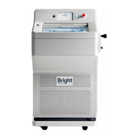
BRIGHT OTF 5000 User manual

Model shown HS
Serial No:
St Margarets Way Stukeley Meadows Industrial Estate Huntingdon Cambridgeshire England PE29 6EU
Tel: +44 (0) 1480 454528/451980/451499 . Fax: +44 (0) 1480 456031
Email: sales@brightinstruments.com . Website: www.brightinstruments.com
INSTRUCTION MANUAL
OTF 5000 All Models
BS EN ISO 9001:2008
Certificate No. Q 05456


OTF 5000/HS/LS-001/2/3/4 Iss 4 June 2012
i
CONTENTS
SAFETY INFORMATION 1
CONSUMER PROTECTION 1
ELECTRICAL 1
MICROTOMES KNIVES/BLADES 1
OPERATION 1
LOW TEMPERATURES 2
ACCESSORIES 2
PRODUCT SAFETY SUGGESTIONS 2
DECONTAMINATION CERTIFICATES 2
WARNING 2
WARRANTY 3
1.1 RECEIPT AND UNPACKING 3
1.1.1 RECEIPT 3
1.1.2 UNPACKING 3
1.2 ASSEMBLY AND INSTALLATION 4
1.2.1 FITTING THE HANDWHEEL 4
1.2.2 DRAIN TUBE AND PLUG 4
1.2.3 INSTALLATION OF TRAYS AND SHELVES –FIG 2 4
1.2.4 FROST ELIMINATION COVER –FIG 3 5
1.2.5 INSTALLATION OF THE MICROTOME (and REMOVAL) 5
1.2.6 INSULATED NIGHT PLUG 6
1.2.7 /X - THIN SECTION CONVERSION KIT (where applicable) 6
1.2.8 /U - ULTRA VIOLET LIGHT DECONTAMINATION UNIT (where applicable) 6
1.2.9 /Y - GLOVE PORT (where applicable) 6
1.2.10 /V - FOOT SWITCH (where applicable) 6
1.2.11 POSITIONING 7
1.3 ELECTRICAL 7
1.3.1 SETTLING 7
1.3.2 ELECTRICAL REQUIREMENTS 7
1.3.3 ELECTRICAL SAFETY 7
2OPERATING INSTRUCTIONS 8
INTRODUCTION 8
SWITCHING ON 8
2.1 CABINET CONTROLS 9
2.1.1 MAINS SWITCH (Located on side panel) 9
2.1.2 LIGHT SWITCH BUTTON 9

OTF 5000/HS/LS-001/2/3/4 Iss 4 June 2012
ii
2.1.3 DEFROST SWITCH (Located on the side panel) 9
2.1.4 DEFROST CLOCK (Located on side panel) 9
2.1.5 CHAMBER TEMPERATURE 10
2.1.6 /D - CRYOMATIC SPECIMEN TEMPERATURE CONTROL (where applicable) 11
2.1.7 QUICK FREEZER PLATE 11
2.1.8 /QF - SPECIMEN QUICK FREEZER (where applicable) 11
2.1.9 /EC or /LT or /LOWEC - DUAL REFRIGERATION SYSTEM (where applicable) 12
2.1.10 MOTORISED ADVANCE/REWIND (where applicable) 13
2.1.11 HANDWHEEL 13
2.1.12 /MR or /MR(S) - MOTOR DRIVE (where applicable) 14
2.1.13 /C - ELECTRONIC SECTION COUNTER (where applicable) 14
2.1.14 /V - FOOT SWITCH (where fitted) 14
2.1.15 /U - ULTRA VIOLET LIGHT DECONTAMINATION UNIT (where applicable) 15
2.1.16 /Y - GLOVE PORT (where applicable) 15
2.2 MICROTOME CONTROLS - STANDARD KNIFE BLOCK 16
2.2.1 KNIFE GUARDS 16
2.2.2 KNIFE HOLDER 17
2.2.3 /X - THIN SECTION CONVERSION KIT (where applicable) 17
2.2.4 ANTI-ROLL ASSEMBLY 18
2.3 MICROTOME CONTROLS - Quick Release Feather Blade Holder 20
2.3.1 BLADE GUARDS 21
2.3.2 BLADE HOLDER 21
2.3.3 ANTI-ROLL ASSEMBLY 21
2.4 Common MICROTOME CONTROLS 23
2.4.1 COARSE ADVANCE CONTROL 23
2.4.2 SECTION THICKNESS CONTROL 23
2.4.3 ADVANCE / REWIND CONTROL 23
2.4.4 SPECIMEN HOLDER 24
2.5 ALTERNATIVE FEED SCREWS 24
3CUTTING & COLLECTING SECTIONS 25
3.1 BASIC FREEZING TECHNIQUES 25
3.1.1 LIQUID NITROGEN 25
3.1.2 CARBON DIOXIDE - GAS 25
3.1.3 CARBON DIOXIDE - SOLID 25
3.1.4 FREEZER PLATES 25
3.1.5 BRIGHT CLINI-RF 26
3.2 FITTING THE SPECIMEN 27
3.3 TRIMMING THE SPECIMEN 28
3.4 SECTION CUTTING AND COLLECTION 28
3.5 HINTS ON SECTIONING 28
3.6 FROZEN SECTIONING - A PROBLEM SOLVING GUIDE 29
3.6.1 SOLUTIONS - CHECK LIST 29
3.6.2 SPECIFIC PROBLEMS 29
3.7 CUTTING TEMPERATURES 30
3.7.1 FRESH, UNFIXED TISSUE 30

OTF 5000/HS/LS-001/2/3/4 Iss 4 June 2012
iii
3.7.2 FIXED TISSUE 31
4.1 DAILY CARE 31
4.2 AUTOMATIC DEFROST CYCLE 31
4.3 TOTAL DEFROSTING 31
4.4 MICROTOME KNIVES 31
4.5 OPERATING IN EXTREME CONDITIONS 32
4.6 SERVICING AND REPAIRS 32
4.6.1 UK 32
4.6.2 REST OF WORLD 33
4.7 SIMPLE SERVICING/REPAIR PROCEDURES 33
4.7.1 CHANGING FUSES 33
4.7.2 CHANGING FLUORESCENT TUBE 33
4.8 DECONTAMINATION 33
5ACCESSORIES 34
5.1 OBJECT HOLDERS 34
5.2 KNIVES 36
5.3 LEVER RELEASE FEATHER BLADE HOLDER 37
5.4 MAGNAPLATE, ANTI-ROLL PLATE 37
5.5 MAGNACUT, MAGNETIC DISPOSABLE BLADE SYSTEM 37
5.6 Easi-Set, ANTI-ROLL PLATES 38
5.7 FEED SCREWS 38
5.8 CRYOSPRAY 39
5.9 CRYO-M-BED 39
6SPARE PARTS 39
6.1 5040 Parts please see Appendix Drawing and Part List 39
6.2 5040 ELECTRONICS SPARE PARTS 39
6.3 ACCESSORIES AND CONSUMABLES 40
6.4 A KNIFE SHARPENING SERVICE IS AVAILABLE 40

OTF 5000/HS/LS-001/2/3/4 Iss 4 June 2012
iv
7PRODUCT INFORMATION 41
SPECIAL FEATURES: 41
Configurations 41
Basic Specification 41
LS Specification 42
HS Specification 42
Appendices
5040 MICROTOME DRAWINGS (relevant to Model)
5040 MICROTOME PART LIST (relevant to Model)
ELECTRICAL CIRCUIT DIAGRAMS (relevant to Model)
Material Safety Sheet: CRYOSPRAY 57713
Material Safety Sheet: CRYO-M-BED 53581
Material Safety Sheet: LOW TEMPERATURE OIL 57491
DECONTAMINATION CERTIFICATE

OTF 5000/HS/LS-001/2/3/4 Iss 4 June 2012
1
SAFETY INFORMATION
CONSUMER PROTECTION
The Consumer Protection Act 1987 Part 1, refers to Product Liability. This legislation was
issued as a direct result of an EC Directive to all member states and has been in force with
effect from 1st March 1988.
Bright Instrument Co Ltd, ever mindful of the need to ensure that their products are not subject
to misuse and/or incorrect handling, have made it their aim to communicate any possible
dangers to their customers.
Whilst Bright Instrument Co Ltd markets products manufactured to the highest safety standards,
it is in the interest of the purchaser that he is aware of the resultant dangers of misuse and/or
incorrect handling of these products.
Your attention is therefore drawn to the following precautions:
ELECTRICAL
a Warnings - A warning notice is fixed to the instrument stating that it should be disconnected
from the power supply before removing the panels. This warning should be strictly observed.
This cryostat is fitted with an in line mains filter which may affect portable appliance test
results.
b Fuses - Fuse ratings are clearly indicated on all fuse panels adjacent to the fuse holder. If
and when replacement is necessary, the correct fuse rating must be adhered to.
c Earthing (Grounding) - A protective earth terminal is fitted, and must be used in all two wire
installations.
MICROTOMES KNIVES/BLADES
Microtome knives and blades can be hazardous in the laboratory. Personnel should be made
aware of the dangers and observe the following warnings:
a DO NOT leave the microtome unattended with an exposed knife in position. Remove the
knife or cover it with the guards provided.
b DO NOT leave knives lying around. Place knives that are not in use in their boxes.
c DO NOT carry knives unless secure in the box provided.
d DO NOT clean the knife along its length. Wipe from the back edge to the cutting edge.
e REMEMBER that even used knives are dangerous - they are still sharp and may have been
used to cut potentially infectious specimens.
f DISPOSE of used knives with the same care as other sharp objects. On no account should
used knives be placed in waste bins.
OPERATION
When placing object holders in the microtome, when orientating, manipulating or in any way
placing fingers in a position above the knife edge - ensure that the handwheel is locked and
knife guards are in position.

OTF 5000/HS/LS-001/2/3/4 Iss 4 June 2012
2
LOW TEMPERATURES
Parts of this instrument may attain temperatures as low as minus 50ºC. It is important to avoid
allowing bare skin to touch such cold surfaces - when in doubt, wear gloves. Avoid touching the
knife - it is cold as well as sharp! Always use knife guards.
ACCESSORIES
Fluids supplied as accessories with Bright instruments, such as Cryospray 134, Cryo-M-Bed
and microtome oil, are strictly for laboratory use only. They should not be taken by mouth and
precautions afforded to other laboratory chemicals should be adhered to. Please refer to the
material safety data information, towards the back of this instruction manual, for further details.
Care must be taken when using Cryospray 134. The risk of creating an aerosol of potentially
infectious tissue particles must be borne in mind.
PRODUCT SAFETY SUGGESTIONS
All Bright Instrument Co Ltd personnel are encouraged to make suggestions regarding product
safety. We also welcome such suggestions from our customers. They may be submitted by
completing the appropriate (Safety) section of the Quality Survey Record Form supplied with all
Bright instruments, or alternatively by letter, telephone, fax or email. All communications should
be directed to our Quality Assurance Department and will be acknowledged.
DECONTAMINATION CERTIFICATES
IMPORTANT
If the instrument or any part of it is to be returned to Bright Instrument Co Ltd, please note the
following:
1 If the instrument or any part of it has been exposed to or been in contact with potential
pathogenic or radioactive material, it is essential that it be decontaminated.
2 A code of practice for decontamination has been prepared by the Health Services Advisory
Committee and endorsed by the Health and Safety Commission, see section 4.8. For the
avoidance of doubt, we require that all instruments or parts returned to us should be
accompanied by a completed decontamination certificate. A copy of this can be found
towards the back of this instruction manual and we suggest you use a photocopy of this.
Alternatively we would be pleased to either post or fax you another copy should you require.
3 Decontamination certification should be faxed to Bright Instrument Co Ltd prior to the unit
being received, or can be attached externally to the carton. Should no decontamination
certificate be received, or the instrument or any part of it be received in a condition that
Bright Instrument Co Ltd consider to be a potential biological hazard, the instrument or part
will be returned, unrepaired, at the expense of the customer.
4 Customs declarations must indicate that the package contains ‘British Returned Goods’.
Failure to do so will involve customs duty payable by us, which will be invoiced to the sender.
WARNING
Before proceeding to Operating Instructions, ensure you are familiar with the contents of the
pages marked ‘Safety Information’. This instrument must only be used by competent persons.

OTF 5000/HS/LS-001/2/3/4 Iss 4 June 2012
3
WARRANTY
The warranty relating to the instrument is outlined in our Terms and Conditions of Sale,
paragraph 6.
Warranty
1. The Seller’s manufactures are carefully inspected and submitted to its standard tests.
2. The Seller warrants all its manufactures to be free from defects in workmanship and
materials under normal conditions of use and service provided always:
3. that if any of the goods so manufactured is alleged to be defective in workmanship and
materials and is returned carriage paid, and protected against damage in transit, to the
Seller’s works, Huntingdon, within 12 months from the date of despatch and if after
examination by the Seller the goods or part of them are found to be so defective then the
Seller will repair or replace them free of charge and will return them to the Buyer, carriage
paid;
4. where any part of the goods manufactured by the Seller is repaired or replaced under the
terms of the foregoing warranty, such warranty shall thereafter be limited to a period of
six months from the date when the goods shall have been re-delivered to the Buyer;
5. this warranty does not apply to any defects caused by wear and tear, incorrect
installation, abnormal conditions of working, accident, mis-use or neglect;
6. that save as in this clause herein before expressed, the Seller shall not be under any
liability for negligence or otherwise in respect of defects in goods delivered or for any
injury, damage or loss resulting from such defects, and the Seller’s liability under this
clause shall be in lieu of any warranty or condition implied by law as to the quality or
fitness for any particular purpose of such goods;
7. this warranty is expressly in lieu of all other warranties, guarantees or liabilities expressed
or implied by any of the Seller’s Representatives or Agents.
For customers in the UK mainland please see our separate Product Warranty sheet.
1.1 RECEIPT AND UNPACKING
This instrument received a final test and inspection prior to despatch from the factory. The
following instructions are given for the re-assembly of the instrument, adjustments and its
correct use. If the instrument is received before preparations for installation are completed; it
should be stored in a clean, dry place and not exposed to dirty or damp conditions. Do not place
or store any items on top of the carton.
1.1.1 RECEIPT
Immediately upon receipt of the instrument, make a careful examination for evidence of damage
encountered in transit. If any damage is found or suspected, notify both the carrier and Bright
Instrument Co Ltd immediately.
1.1.2 UNPACKING
All packing must be carefully removed and parts checked against the enclosed packing list. If
any damage or discrepancy is noted, please inform our agent/distributor, or Bright Instrument
Co Ltd direct, immediately. To prevent damage in transit, the handwheel and microtome have
been removed and packed in separate containers together with the accessories.

OTF 5000/HS/LS-001/2/3/4 Iss 4 June 2012
4
1.2 ASSEMBLY AND INSTALLATION
1.2.1 FITTING THE HANDWHEEL
Push the handwheel over the shaft on the right side of the cabinet. Ensure the pin on the shaft
engages the slot in the centre of the handwheel. Press firmly home, then fit and tighten the
centre screw. Using the special tool provided, 212-053. Older models need a large, flat bladed
screwdriver.
1.2.2 DRAIN TUBE AND PLUG
A small drain plug is fitted to the bottom left corner of the chamber, and a drain tube takes
defrost water out the left side of the cabinet.
Pour approximately 100ml of water down the drain hole and place the tapered plug into position.
The purpose of the water is to act as a vapour lock to prevent the ingress of moist laboratory air.
The drain plug should be left in position except when cleaning is carried out.
1.2.3 INSTALLATION OF TRAYS AND SHELVES –FIG 2
A pair of stainless steel trays is packed separately and each marked left and right. Install the
right tray first, placing it horizontally on the right hand side of the chamber below the drive shaft
projecting from the cabinet wall. Ensure that the rearmost part of the tray firmly locates on the
rear wall of the cabinet. After fitting the microtome, (see section 1.2.5), install the left tray in a
similar way.
(Alternatively, for cryostats with the /QF option, install the left tray behind the quick freezer,
locating on the two studs provided. Fit the small shelf to the front of the /QF).
Next, fit the long narrow shelf to the upper right hand wall of the chamber, locating onto the two
studs provided. The trays and shelves are loose fitting and are readily removed for cleaning etc.

OTF 5000/HS/LS-001/2/3/4 Iss 4 June 2012
5
Fig 5
1.2.4 FROST ELIMINATION COVER –FIG 3
1.2.5 INSTALLATION OF THE MICROTOME (and REMOVAL)
WARNING - The microtome weighs approximately 15kg. Ensure that adequate precautions are
taken to prevent injury, i.e. back strain, when lifting and moving. The use of an industrial,
personal lifting belt is highly recommended.
Remove the shipping stay as follows:
1 Loosen the specimen clamp and knife clamp screws FIG 4(5).
2 Slide out the shipping stay and the packaging.
3 Retain the stay for possible future use and dispose of the packaging.
Now install the microtome:
1 With your right hand under the front of the microtome and your left hand under the rear left
side, carefully lift the microtome into the chamber.
2 Locate it on the four studs in the chamber. Look for the reflection of the holes in the base of
the microtome to locate the front two studs - the rear ones will follow.
3 Loosen the two recessed grub screws in the coupling on the Drive shaft projecting from the
right chamber wall.
4 Slide the coupling onto the corresponding shaft on the microtome, ensuring that the left
screw is exactly over the dimple in the microtome shaft. Tighten the left screw.
5 Now rotate the handwheel until the arrow head (<) points to the right screw as shown below
(Fig 4), then tighten the screw
Check that the coupling has been correctly fitted by rotating the handwheel, the specimen arm
should rise as the handwheel’s knob moves upwards, and should be at the bottom of the stroke
when the handwheel knob is at its lowest position.
6 Install the rewind control knob on the top of the microtome. Please
note that this knob must be removed prior to lifting the microtome
out of the chamber.
Frost Elimination Cover
Place on the quick freezer plate
Fig 4
Position Arrow as shown
Before tightening screws all the way, wiggle
coupling to ensure screw locates in dimple
Drive Shaft

OTF 5000/HS/LS-001/2/3/4 Iss 4 June 2012
6
7 For /MAR - Motorised Advance Rewind (where applicable): When fitting the microtome, the
electrical socket and plug must be connected and screwed together. Before removing the
microtome from the cryostat, the electrical socket and plug must be unscrewed and
disconnected. Ensure that the power supply is disconnected before installing or removing the
microtome.
8 For /D - Cryomatic Specimen Temperature Control (where applicable): Install the
temperature heater/vee block in the microtome head first and then route the cable around
the microtome using the cable clips already fitted. Ensure that the power supply is
disconnected before installing or removing the microtome.
9 Position the left tray.
10 Finally, place the plastic brush and debris tray in position at the front of the microtome,
ensuring it is in contact with the base of the microtome.
To Remove the Microtome (Refer to Fig 4):
1 Remove Debris Tray in front of microtome.
2 Remove Advance/Rewind Knob (on top of microtome) by pulling upward.
3 Remove LH tray by sliding forward and up.
4 If a heated v-block is fitted then lift it & move it out of the way
5 Remove Coupling by loosening grub screws and slide onto Drive shaft (see Fig 4)
6 Use 2.5mm Allen Key (supplied)
7 If MAR then unplug socket at bottom Left of Tank.
8 With your right hand under the front of the microtome and your left hand under the rear
left side, carefully lift the microtome from the pins in the chamber.
1.2.6 INSULATED NIGHT PLUG
Unpack and store ready for use when required
1.2.7 /X - THIN SECTION CONVERSION KIT (where applicable)
Refer to section 2.2.3
1.2.8 /U - ULTRA VIOLET LIGHT DECONTAMINATION UNIT (where
applicable)
Unpack and store ready for use when required
1.2.9 /Y - GLOVE PORT (where applicable)
For access to the cryostat chamber, press the glove port unit into the lower half of the window
recess and then close the window until it seals against the glove port unit.
1.2.10 /V - FOOT SWITCH (where applicable)
Plug the foot switch lead into the socket on the lower front surface of cabinet, right hand side.
Place the foot switch on the floor in a convenient position.

OTF 5000/HS/LS-001/2/3/4 Iss 4 June 2012
7
1.2.11 POSITIONING
Fit the two spacer brackets to the rear of the cabinet and ensure that nothing will block the vents
on this rear panel. The instrument should be positioned on a level floor so that an unrestricted
air flow through the cooling vents is obtained. This is necessary in order to ensure adequate
ventilation, and can be achieved by leaving a gap of 100mm minimum at the rear of the cabinet.
Ensure that the instrument has been positioned away from direct, hot sunlight and is in a
location completely free from draughts, e.g. fans, air conditioning units, air inlets and air outlets
etc. The instrument is mounted on castors, two of which are lockable, to give easy movement.
1.3 ELECTRICAL
1.3.1 SETTLING
During transit the oil in the compressor will have been subject to movement, so it is important to
let the cryostat settle before switching on. We recommend the instrument is left standing for at
least eight hours, and preferably overnight, before switching on.
Moving the instrument around on its castors, e.g. from one laboratory to another, will not affect
the compressor oil.
1.3.2 ELECTRICAL REQUIREMENTS
The supply cord of the instrument should be connected to any ordinary electrical outlet
(minimum 13 amps for 220/240V), a 13 amp fuse should be incorporated in the line. (minimum
20 amps for 110/115V) Check the voltage stamped on the nameplate, located on the back of
the cabinet, with your supply.
The connections are:
Brown - Positive (live)
Blue - Negative (neutral)
Yellow/Green - Earth (ground)
1.3.3 ELECTRICAL SAFETY
Where earth cables may have to be removed from panels for servicing or repair purposes, care
should be taken to replace them when replacing the panel. Earth points are identified by a
yellow and green striped circular sticker.
Where earth connections are taken through connectors, then the connector must be rated to
take the maximum fault current. The machine should be disconnected before such connectors
are separated for servicing purposes.
This cryostat is fitted with an in line mains filter which may affect portable appliance test results.

OTF 5000/HS/LS-001/2/3/4 Iss 4 June 2012
8
2 OPERATING INSTRUCTIONS
INTRODUCTION
Based on the long-established and reliable OTF/AS cryostat, the new OTF5000 brings Bright
cryostats completely up to date. New styling with improved user ergonomics, the latest blade
systems in the ever-reliable and powerful 5040 microtome, a huge choice of options plus
money-saving package deals make these cryostats absolutely unique.
They are suitable for an endless range of applications and in the correct configuration are
capable of cutting a wide diversity of specimens from undecalcified bone to brain, resins,
plastics and plant tissue as well as more usual soft tissue. Allowing full anti-roll plate adjustment
for perfect results coupled with long lasting temperature stability, the OTF5000 can truly be
described as complete.
FIG 1
SWITCHING ON
On receipt of your new Bright instrument, please refer to the Receipt and Unpacking section
and the Assembly and Installation section of this Handbook
As part of its policy of continual improvement, Bright Instrument Company Limited reserves the
right to incorporate changes, or make additions to, without prior notice. There may, therefore, be
minor detail differences between the information in this manual and your instrument. These
differences will not affect the safety and use of the instrument.
After settling, switch on the power (see section 2.1.1). Initially the LED displays will flash for a
few seconds. Once the displays are constant, the required chamber temperature can be set
(see section 2.1.8). After the cryostat has reached the set chamber temperature, leave for a
further two hours before attempting to cut sections.

OTF 5000/HS/LS-001/2/3/4 Iss 4 June 2012
9
2.1 CABINET CONTROLS
FIG 6
2.1.1 MAINS SWITCH (Located on side panel)
This switch is used to connect the power supply to the cryostat.
Operate this switch to switch the instrument on and off.
2.1.2 LIGHT SWITCH BUTTON
This switch operates the fluorescent lamp, which should be switched off whenever the night
plug is in position.
2.1.3 DEFROST SWITCH (Located on the side panel)
This switch will only activate in conjunction with the defrost clock settings. When on, a heater is
activated which is in contact with the evaporator cooling fins during the defrost cycle and the
switch will illuminate.
2.1.4 DEFROST CLOCK (Located on side panel)
This clock sets the time required for the routine defrosting of the evaporator cooling fins. During
the defrost cycle the clock switches off the refrigeration unit and activates a low power heater,
which clears frost from the evaporator cooling fins. The defrost clock should be set so that it
initiates the defrost at night, and the defrost duration is sufficient to clear the evaporator cooling
fins without the rest of the chamber rising above 0ºC.
Set the 12 hour analogue clock to the current time by turning the clear plastic disc with your
finger. Note that because the defrost needs to run on a 24 hour cycle, make sure that the small
black arrow is aligned with the correct number of the outer ring e.g. if the time is 4.00pm, then
the corresponding number is 16.
The defrost time is set in the factory to start at midnight for 30 minutes, but may be altered by
moving the pins which are around the edge of the clock face. If the time already set provides
inadequate defrosting, it is recommended that a second 30 minute cycle is programmed to
operate several hours later (e.g. at 12 midnight and 6am).
Important: do not increase the defrost time above 30 minutes, as the microtome and chamber
may warm up above 0ºC, causing pools of water to form and subsequently freeze to form ice.
In conditions of high humidity some experimentation may be required to obtain optimal
defrosting (see section 4.5).
Please note that the defrost switch is normally left in the ON position.
There is an override switch on the defrost clock: turning the small black button switches the
defrost cycle on or off.
Temperature Alarm
Fig 5

OTF 5000/HS/LS-001/2/3/4 Iss 4 June 2012
10
2.1.5 CHAMBER TEMPERATURE
FIG 7 To set the chamber temperature, press and release the Set button
and then press the Up or Down buttons until the desired
temperature is set. After 5 seconds the actual chamber
temperature will show.
To view the Set temperature, press and release the Set button.
WARNING: Do not hold the Set button down for more than six
seconds as the control will go into a diagnostic/calibration mode. If the diagnostic/calibration
mode is selected in error take the following steps:
a If Up or Down have not been pressed (i.e. no new parameters have been entered), simply
leave for 20 seconds. Display will revert to normal.
b If new parameters have been selected contact Bright Instrument Co Ltd or your local
representative for advice.
Temperature Alarm
The chamber temperature controller also features an alarm setting which is audible and
connected to an Alarm LED (shown in Fig 5). The Alarm setting is pre-set at the factory.
The alarm function warns the operator if there is a significant deviation from the set chamber
temperature, so that corrective action can be taken –See Trouble Shooting below.
The controller is factory set with a 2ºC control differential, an 8ºC High Alarm setting and a 20ºC
Low Alarm setting. This means it operates in the following way:
The alarm (light and audible) will activate if the working chambers warms up 8ºC more than the
set chamber temperature or if the chamber temperature goes 20ºC colder than the set
temperature. The Alarm can be manually reset by pressing any one of the 3 Controller buttons
on the Chamber Temperature Controller shown in Fig 7.
On start up, the Alarm is deactivated for 3 hours to allow the cryostat reach its set chamber
temperature. It will then automatically become activated.
During ‘Defrost’ the power to the Controllers is switched off. When defrost is complete the power
will be switched back on to the controllers. Please note that the Alarm will revert back to start up
status and will not become active for 3 hours.
Trouble Shooting
The Alarm may sound in the following conditions:
- If continual work is carried out for long periods with the window open & hands in the
chamber (particularly at low temperature setting), the chamber may warm enough to set
the alarm off
- If the temperature has been reset by more than 8ºC (High Alarm setting) or less than 20ºC
(Low Alarm setting), the alarm will sound until the temperature is within the range.
- Placing a warm microtome in a cold chamber could also cause the alarm to activate.
The correct action to follow is:
- Reset the Alarm as detailed above
- Close the window and see if the chamber temperature cools down
- If it does then continue working
If the chamber continues to warm there is a strong possibility of a fault, call your service
engineer
If the unit returns to its correct operating temperature it could be that the Alarm parameters
need to be adjusted to suit your working conditions. If required contact your service engineer for
instructions.

OTF 5000/HS/LS-001/2/3/4 Iss 4 June 2012
11
2.1.6 /D - CRYOMATIC SPECIMEN TEMPERATURE CONTROL (where
applicable) FIG 8
To set the specimen temperature, press and release the Set
button and then press the Up or Down buttons until the desired
temperature is set. After 5 seconds the actual temperature will
show. To review the Set temperature at any time press and
release the Set button.
NB: This system can only set temperatures above the selected
chamber temperature, not colder.
2.1.7 QUICK FREEZER PLATE
FIG 9
Remove the frost elimination cover before using the quick freezer plate.
This plate runs at or below the set chamber temperature (typically 10ºC
below chamber temperature) and is useful for storage or pre-cooling of
knives etc. Although it is possible to freeze fresh tissue on the quick
freezer plate, it is generally preferable to use a much colder medium.
The temperature of the quick freezer plate is displayed constantly on
the main control panel. Do not forget to replace the frost elimination
cover after using the quick freezer plate, this helps prevent a build up of
frost.
2.1.8 /QF - SPECIMEN QUICK FREEZER (where
applicable)
FIG 10
The specimen quick freezer (/QF) is
designed for rapid freezing of specimens
mounted on specimen holders. Cooled
by a separate compressor, the /QF can
either run continuously or be switched
on 30 minutes before use. Please note
that the operation of the freezer is
dependant on the operation of the
chamber compressor. The /QF will not
function when a chamber temperature
warmer than -15ºC is selected. Optimum
performance is achieved with chamber
temperatures of -20ºC or colder.
SAFETY: The quick freezer operates at extremely low temperatures and may cause freeze
burns. Suitable protective gloves should be worn when handling frozen specimen holders.
Switching On
1 Ensure that the /QF is clean and dry before switching the cryostat on, as the cold chamber
temperature will freeze the quick freezer even when it is switched off.
2 Ensure that the appropriate sleeve is fitted into the freezer block to accept the object holder
to be used, (a sleeve for the standard 22mm object holder is fitted and a sleeve for the
37mm object holder is supplied in addition).

OTF 5000/HS/LS-001/2/3/4 Iss 4 June 2012
12
3 Place the /QF cover over the /QF, this will reduce the rate that frost forms.
4 Switch the /QF on at least 30 minutes before it is required for use. Please note that in certain
conditions the /QF compressor will not operate immediately. This is because the operation of
the /QF compressor is dependant on the temperature of a heat exchanger, which is cooled
by the chamber cooling system. Once the chamber compressor has been running for a few
minutes the /QF compressor will operate and the /QF will start to cool.
Using the /QF
1 Wait until the /QF has reached a temperature of at least minus 70ºC before freezing
specimens. Although specimens will freeze at warmer temperatures the advantages of the
rapid freezing will be lost.
2 Apply a layer of embedding compound to the object holder (which must be above a
temperature of 0ºC), place the specimen on top of the object holder and then insert the
object holder into the sleeve of the /QF. While this is freezing through, but before the top
surface of the embedding compound goes solid, apply subsequent layers of embedding
compound if required. Once the specimen is frozen all the way through, remove the object
holder, complete with the specimen and place it in the vice jaws ready for sectioning.
Note - the /QF is obviously very cold and if the object holder is left in it for some length of time
the specimen will achieve a temperature of -80ºC. If the specimen is then placed in the vice
jaws it will be far too cold to cut and if attempted, damage may occur to knives. It is imperative
that a little time is allowed for the specimen temperature to equalise before cutting commences.
Defrosting
Defrosting of the /QF is controlled by the cryostats defrost clock. It is recommended to select 30
minutes defrost each night.
Always switch off the /QF and remove its cover at the end of the day when defrosting is
required. Failure to do this will result in rapid frosting of the /QF once it starts working. This is
due to the increased humidity in the chamber and /QF resulting from the defrosting. Once the
chamber has cooled to its normal working temperature, this humidity will have reduced.
At the start of the day, switch on the /QF and replace its cover.
Temperature Calibration
The temperature display has been calibrated to read accurately between -70ºC and -80ºC. It
may read inaccurately at temperatures significantly out of this range (e.g. at room temperature).
2.1.9 /EC or /LT or /LOWEC - DUAL REFRIGERATION SYSTEM (where
applicable)
Press the DUAL button on the front panel to initiate use of both
compressors.
NOTE: When running without the DUAL light illuminated, the
cryostat will automatically switch between one compressor and
the other in order to reduce wear on the ocmpressors.
Please note that there will be a pause of 40 to 70 seconds
between the compressors starting in order to reduce current
surges.
In the DUAL mode, full advantage can be taken of the extra refrigeration power available, and
an extra 5ºC can be achieved in the cryostats freezing performance.
FIG 11

OTF 5000/HS/LS-001/2/3/4 Iss 4 June 2012
13
2.1.10 MOTORISED ADVANCE/REWIND (where applicable)
FIG 12
Warning:
Do not operate the rewind motor when the cutting arm is in motion.
Only operate the rewind motor with the cutting arm at the rest
position. The advance motor may be operated when the cutting arm
is in motion. Operating outside these parameters can cause damage
to the mechanical components of the instrument.
Motorised Specimen Advance
1 With the specimen in place set the specimen thickness control to 0µm
2 Fully rewind the specimen.
3 Adjust the position of the knife carriage with knife to specimen clearance set to a minimum
(refer to section 2.2.2 to install a knife and for recommended knife angle).
4 Lock the knife carriage.
5 Begin advance, with cutting arm fully up, by ’toggling’ the Advance switch whilst rotating the
handwheel. The longer the switch is pressed the thicker the section. If the Advance switch is
pressed for more than 1.5 seconds, a faster advance of the specimen is achieved.
Motorised Specimen Rewind
1 To fully rewind specimen, ’toggle’ the Rewind switch for a minimum of 1.5 seconds and
release. The feedscrew will automatically stop when fully rewound.
2 To stop the specimen rewinding during the period, ’toggle’ the Advance switch and release
immediately.
For small rewind increments, quickly ‘toggle’ the Rewind switch.
2.1.11 HANDWHEEL On instruments without /MR or /MR(S) the
handwheel is fitted with a locking lever
which locks the wheel (and therefore the
specimen arm) in a variety of positions.
Where /MR or /MR(S) is fitted, leave the
specimen arm in the top position before
switching off motor. The arm and handwheel
can now be locked in position by pushing in
the connecting rod knob.
For safety, the handwheel MUST BE LOCKED whenever a specimen is being fitted,
manipulated or removed.
Connecting rod knob
FIG 14 /HS and models with /MR and /MR(S)

OTF 5000/HS/LS-001/2/3/4 Iss 4 June 2012
14
FIG 15
2.1.12 /MR or /MR(S) - MOTOR DRIVE (where applicable)
To operate the motor drive:
1 Rotate the handwheel while pushing the small connecting rod knob. The
rod will engage through to the motor drive, and the handwheel is now
locked into the motor drive.
2 Switch on Drive. The green Power light will illuminate.
3 Select Trim mode (for continuous running of motor drive).
4 After ensuring the specimen will not collide with the knife, press Start
the Drive.
5 Use the Speed Control to adjust cutting speed
6 Adjust the Zone control. The space between the Upper and Lower positions indicates that
part of the specimen travel which is determined by the speed control.
7 By switching to Single the arm will be made to stop at the bottom of each stroke, allowing
section collection.
8 To stop the drive, press Stop. Start and Stop functions can be used at any time.
Pull out the connecting rod knob to operate the microtome manually.
The Emergency Stop button stays in when pressed. Twist button in direction of arrows to
release. Then press Start to continue.
2.1.13 /C - ELECTRONIC SECTION COUNTER (where applicable)
When the cryostat’s power is on, the preset digital counter will remain illuminated at all times.
1 Use the + and - buttons to set the desired preset count, up to 9999 is possible. Remember
that without a programmed setting the motor will not run.
2 Press the Reset button and then start as stated in /MR instructions (section 2.1.13 above).
The counter will then count up to the preset count and then stop.
3 Repeat step 2 to continue using the counter or go back to step 1 if a new preset count needs
to be entered.
2.1.14 /V - FOOT SWITCH (where fitted)
When the motor drive is in use the left and right foot switches will duplicate the action of the
Stop and Start buttons respectively. A combination of both hand (using the Stop and Start
buttons) and foot (using the foot switch) operations may be used.
Table of contents
Other BRIGHT Laboratory Equipment manuals
Popular Laboratory Equipment manuals by other brands

WPI
WPI Nanoliter 2000 instruction manual

ZINEXTS
ZINEXTS MagPurix 24 EVO instruction manual

ELITechGroup
ELITechGroup AEROSPRAY GRAM 7322 Applications manual

IKA
IKA IC control operating instructions

Awareness Technology
Awareness Technology Stat Fax 1904 Plus Operator's manual

Techne
Techne TC-412 Operator's manual

Ihlas Ev Aletleri
Ihlas Ev Aletleri aura Cebilion iflow 101IFL user manual

TMC
TMC STACIS 2100 Installation & operation manual

Kodak
Kodak X-Omat 460 RA Processor Service manual

Nakanishi
Nakanishi PRESTO II Operation manual

Leica
Leica RM2235 user manual

Medic Therapeutics
Medic Therapeutics MT-UVWA-001 manual