Lonza PAGEr Minigel Chamber User manual

Lonza Rockland, Inc.
www.lonza.com
Tech Service: 800-521-0390
Customer Service: 800-341-1574
Document # 18928-0305-01
Rockland
,
ME 04841 USA
IMPORTANT USER INFORMATION
This Instruction Manual will explain how to use this
product safely and effectively. Please read and
carefully follow the instruction manual in its entirety.
The triangle/exclamation mark symbol
alerts the user of the product to important
operational, maintenance, and/or warranty
requirements.
The triangle/lightning bolt symbol alerts the
user of the product to potentially hazardous
electrical exposure.
Failure to adhere to the instructions could result in
personal and/or laboratory hazards, as well as invalidate
any warranty. Always turn off the DC power source prior
to disconnecting power cords from the product.
Disconnect power cords from the power source first and
then from the product. For maximum safety, always
operate this system in an isolated, low traffic area, not
accessible to unauthorized personnel. Never operate
damaged or leaking equipment.
WARRANTY AND LIABILITY
This product was produced utilizing the highest practical
standards of materials, workmanship, and design.
Lonza Rockland, Inc. warrants that the product has been
tested and will meet or exceed published specifications.
This warranty is valid only if the product has been
operated and maintained according to the instructions
provided.
Lonza Rockland, Inc., warrants this product to be free
from defects in materials and workmanship under normal
service for one year from date of shipment. If the
product proves defective during this period, Lonza
Rockland, Inc., will repair or replace it at our option, free
of charge, if returned to us postage prepaid. This
warranty does not cover: damage in transit, damage
caused by carelessness, misuse or neglect, normal wear
through frequent use, damage caused by solvent
corrosion, damage caused by improper handling or user
alteration, nor unsatisfactory performance as a result of
conditions beyond our control. Lonza Rockland, Inc.,
shall in no event be liable for incidental nor
consequential damages, including without limitation, lost
profits, loss of income, loss of business opportunities,
loss of use and other related damages, however caused,
nor any damage arising from the incorrect use of the
product.
SECTION 1
General Information
1.1 Introduction
The PAGEr Minigel Chamber is designed for optimal
performance of PAGEr® Precast Gels (Lonza).
The unit is also compatible with many standard precast
minigels. The simple lock-in-place core design assures a
tight, flat fit and eliminates the risk of buffer leaks. There
is no need to remove the core from the reservoir, simply
insert the gels, close the clamps, fill with buffer and run.
The chamber can run one or two gels and
accommodates a tank blotting module.
Table 1: Components of the PAGEr Minigel Chamber
Cat No Description
59905 PAGEr Minigel Chamber
59906 PAGEr™ Blot Module
59907 PAGEr Minigel Chamber and
Blot Module Kit
(Includes chamber, blotting
cassettes and sponge pads)
1.2 Safety
Power to the PAGEr Minigel Chamber is to be supplied
by an external DC voltage power supply that must be
ground isolated so that the DC voltage output floats with
respect to ground. For any power supply used, the
maximum specified operating parameters for the units
are:
PAGEr™ Minigel Chamber
1

2
Maximum Limits
250 VDC
30 watts power
150 mA current
60ºC ambient temperature
Current to the unit, provided from the external power
supply, must enter the unit through the lid assembly,
providing a safety interlock to the user. Current to the
unit is broken when the lid is removed.
Do not attempt to use the unit without the safety lid,
and always turn the power supply off before
removing the lid, or when working with the unit in
any way. Follow safety precautions specified by the
power supply manufacturer.
Important: After each use, rinse all parts with
de-ionized water.
SECTION 2
Description of Parts
2.1 Unpacking and Components
Please verify that your unit comes complete with the
following components:
• Lower reservoir
• Safety cover with attached DC power leads
• Core
• 1 blank plate for running single gels (not shown)
• 2 adaptors for running 9 cm gels (not shown)
Section 3
Instructions for Electrophoresis
3.1 Preparing the Electrophoresis Unit
1. Place unit in authorized work area. Remove safety
cover from the assembled unit by simultaneously
pressing down on white push pins with your thumbs,
while lifting up on yellow safety cover with your
fingers. Do not remove safety cover by pulling up
on leads!
Figure 2
2. Remove white core from lower reservoir by grasping
core with one hand and lifting directly up.
NOTE: If desired, gels may be inserted without
removing the core from the reservoir.
Figure 3
Figure 1
3. Open doors on the core assembly by pulling up on
the white latches.
4. Slide pre-cast gel cassette into the core assembly
with the notched plate facing in towards the upper
buffer reservoir as shown in figure 3.
5. If running one gel, slide the blank plate into the side
without the gel. If running a 9 cm x 10 cm cassette,
insert the 9 cm gel adapter, as shown in figure 4.

3
6. Close doors and relatch by pressing down on the
white latches so that the assembly looks like that
shown in figure 5.
7. Place stirring bar, if desired, into bottom of reservoir
in stirring corral.
3.2 Running the Gel
1. Place core assembly into lower reservoir. The anode
(red) and cathode (black) electrodes are color-coded
on both the core/cassette assembly and lower
reservoir. Ensure the red dot on the cassette
assembly is on the same side as the red receptacle
on the lower reservoir. Fill core upper reservoir with
freshly prepared buffer (~ 190 ml).
NOTE: If any buffer is spilled into banana jack
receptacle in lower reservoir, dry completely
using compressed air! Failure to do this will
result in accelerated banana jack corrosion.
Banana jack
receptacles
Figure 6
Figure 4
2. See section 5.3 for recommended buffers.
Pour only enough freshly prepared buffer into
lower chamber so that the final buffer level is
just below bottom of sample wells. Using a
pipette or syringe, thoroughly flush out the
wells.
3. Load samples. If outer lanes do not contain
sample, it is recommended that you run
standards and/or fill outer lanes with loading
buffer to reduce smiling and wrap-around
effects.
4. Attach safety cover and turn on magnetic stirrer
(if desired).
Figure 5
Figure 7
5. Connect the leads to the power supply, matching the
color-coded red-to-red and black-to-black. See
Section 5.1 for recommended power conditions.
Begin separation by electrophoresis. Figure 7
shows the closed unit ready for electrophoresis.

4
3.3 Removing the Gel
1. Turn the power supply off and disconnect the leads
from the power supply. Remove the safety cover
from the unit, by simultaneously pressing down on
the white push pins with your thumbs, while lifting
up on the yellow safety cover with your fingers. See
Figure 2. Do not remove safety cover by pulling
up on leads!
2. Pull up on gel door latches, and open gel door.
Remove gel cassette.
3. Fix and stain gel according to your preferred
method.
Section 4
INSTRUCTIONS FOR WESTERN BLOTTING
4.1 Preparing the Unit for Blotting
1. Remove safety cover from the assembled unit by
simultaneously pressing down on white push pins
with thumbs while lifting up on yellow safety cover
with your fingers. See figure 2. Do not remove
safety cover by pulling up on leads! Remove
white core from lower reservoir by grasping core with
one hand and lifting directly up. Open doors on the
core assembly by pulling up on the white latches.
2. Open blotting cassette (as shown in figure 8) and lay
it flat on the bench.
3. Western Blotting Instructions.
a. Soak gel in 1X Towbin (1X tris-glycine buffer/
20% Methanol) buffer for 10 minutes.
b. Cut a piece of PVDF or nitrocellulose membrane
to fit the gel. Do Not Touch Membrane with
Bare Hands. Wear gloves.
c. Soak membrane in 50% methanol for 30
seconds.
d. Soak membrane in water for 5 minutes.
e. Soak membrane 5 minutes in 1X Towbin buffer
until it no longer floats. Do Not Allow
Membrane to Dry.
f. Cut 1 piece of filter paper 1 mm thick or less to fit
the gel.
g. Soak sponge in 1X Towbin Buffer.
4. Assemble blotting stack. With blotting cassette wide
open assemble components on black side in the
following order, as shown in Figure 9: foam pad,
gel*, buffer saturated transfer membrane, then buffer
saturated blotting paper. Smooth with gloved finger
or roll with glass rod to be sure no bubbles exist
between the gel and the transfer membrane.
Figure 9
*NOTE: to prepare gel for blotting, trim off wells and
any excess gel at the bottom, and invert 180º so that
the large molecular weight proteins are at the
bottom of the cassette. This puts the large proteins
in contact with a stronger field strength and allows
the blotting transfer to take place more efficiently.
5. Insert blotting cassettes into core making sure that
red side faces outward, as shown in figure 10.
Figure 8 Red Side
Figure 10

5
6. Close doors and re-latch by pressing down on the
white latches. If running one blot, slide blank
adapter plate into the side without the blotting
cassette.
4.2 Electro-Blotting Procedure
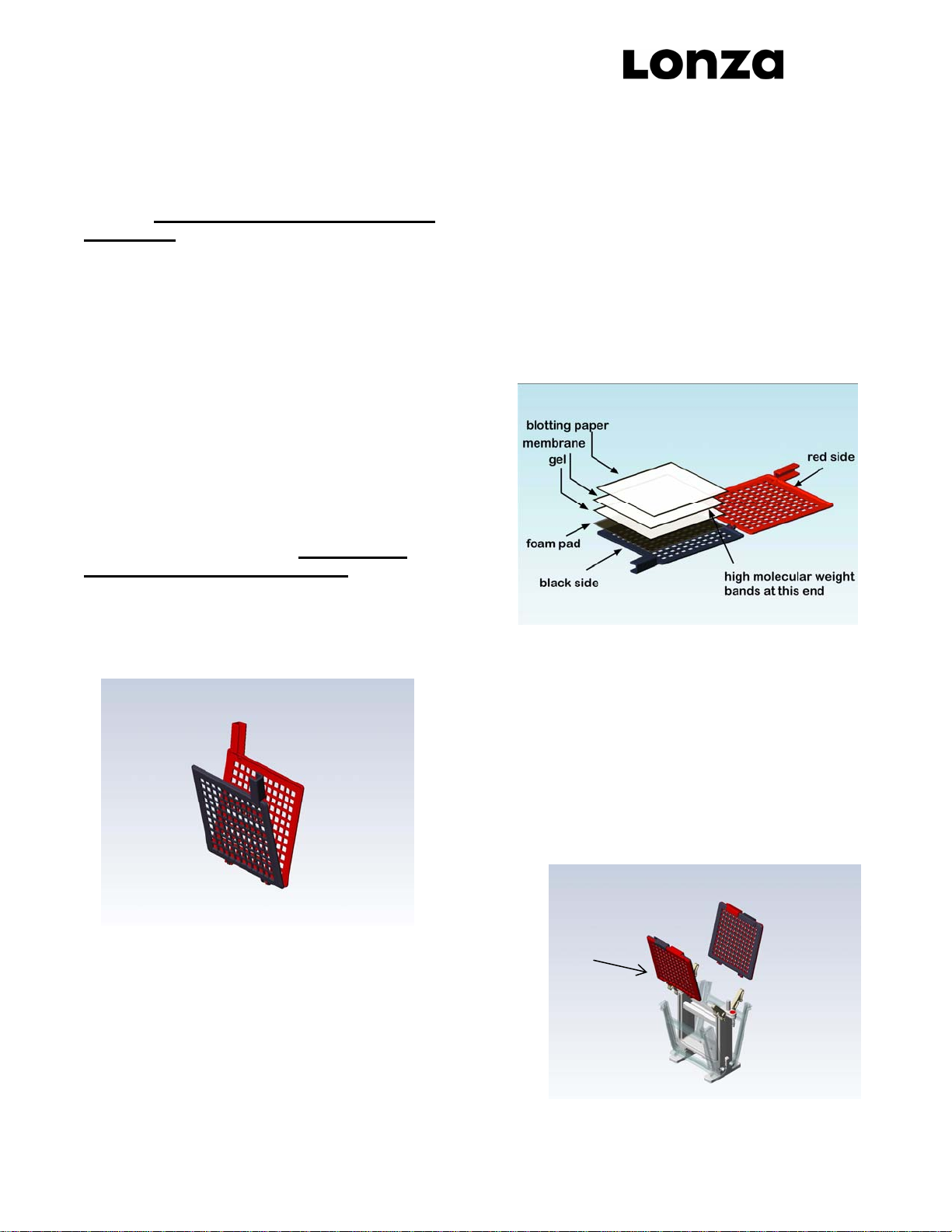
1. Place stirring bar in bottom of reservoir in stirring
corral. Place core/blotting cassette assembly into
lower reservoir. The anode (red) and cathode (black)
electrodes are color-coded on both the core/cassette
assembly and lower reservoir. Ensure the red dot on
the cassette assembly is on the same side as the
red receptacle on the lower reservoir.
2. Pour 1 liter of freshly prepared, chilled (4º) Towbin
buffer into lower buffer reservoir. Buffer will percolate
into central core.
3. Attach safety cover, as shown in figure 11.
4. Connect the leads to the power supply, matching the
color-coded red to red and black to black. See
Section 5.2 for recommended power conditions.
Begin transfer by electrophoresis.
4.3 Removing the Blot
1. Turn the power supply off and disconnect the leads
from the power supply. Remove the safety cover
from the unit, by simultaneously pressing down on
the white push pins with your thumbs, while lifting up
on the yellow safety cover with your fingers. See
Figure 2. Do not remove safety cover by pulling
up on leads!
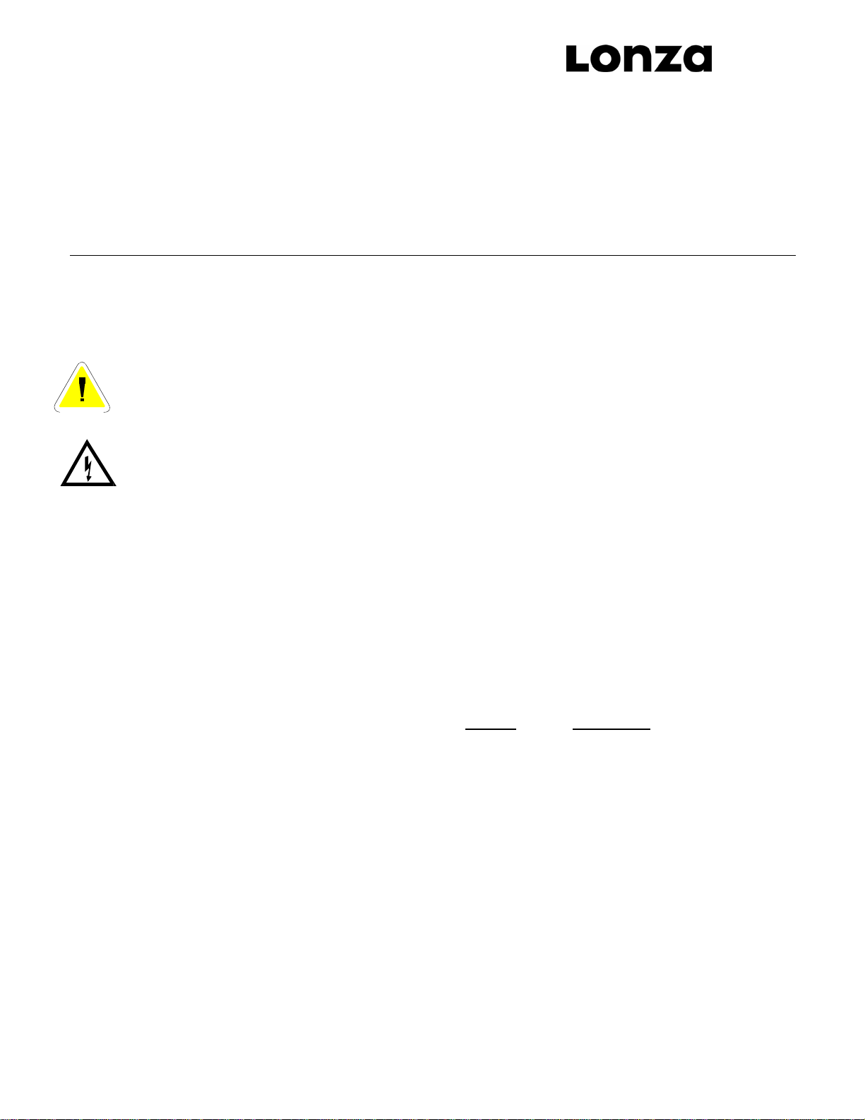
2. Blotting cassettes can be removed by leaving the
core in place and opening the top latches of the
core, opening the doors and lifting the cassettes out.
Unlatch the blotting cassettes and remove blot from
blotting sandwich.
SECTION 5
Running Conditions
5.1 Recommended Power for Slab Gels:
Precise electrophoresis conditions will vary according to
the number and type of gels used, buffer conditions
employed, power input, and the general goal of the
experiment. Refer to section 5.4 for in depth discussions
on practical and theoretical approaches to protein gel
electrophoresis.
Using standard SDS-PAGE buffer systems (see section
5.3). For two 1.0mm thick gels at room temperature use
the following conditions at constant voltage:
200 VDC for ~60 minutes, or if faster runs are
desired, 250 VDC for 30 minutes.
As the thickness of gel increases, the mA’s increase
proportionally.
At constant voltage 200-250 VDC, the proteins will
migrate at a constant rate during electrophoresis with
adequate heating appropriate for denaturing gels.
Increasing the voltage/mA (for each single gel thickness
and percentage) will speed mobility but increase the risk
of overheating.
5.2 Recommended Power for Electro-Blotting:
Using standard SDS-PAGE electro-blotting buffer
systems (see section 5.3) use the following conditions:
100 VDC @ 90 minutes.
5.3 Recommended Buffers
For Best Results use AccuGENE®Electrophoresis
Buffers (see ordering info).
5.4 References
1. Hames, B.D. (ed.) (1998). Gel Electrophoresis of
Proteins. A Practical Approach. 3rd edn. Oxford
University Press, Oxford. Ch. 1,3.
2. Sambrook, J., Fritsch, Russell, D. (2001). Molecular
Cloning. A Laboratory Manual. 3rd edn. Cold Spring
Harbor Laboratory Press, Cold Spring Harbor, New
York. A8.40-A8.55
3. Ausubel, F.M., Brent, R., Kingston, R.E., Moore,
D.D., Seidman, J.G., Smith, J.A., Struhl, K. (ed)
(1993). Current Protocols in Molecular Biology. Vol.
Protein Denaturing
Buffer: Protein Electro-Blotting Buffer:
Figure 11
TG-SDS (1X): TG-SDS Towbin (1X) 20% MeOH:
0.025M Tris base 0.025M Tris base
0.192M Glycine 0.192M Glycine
0.1% (w/v) SDS 0.05-0.1% (w/v) SDS
pH 8.3 20% (v/v) Methanol

6
2, Greene Publishing Associates, Inc. and John
Wiley & Sons, Inc., Ch. 10.
SECTION 6
Maintenance of Equipment
6.1 Care and Handling
The plastic components of the PAGEr™Minigel
Chamber are fabricated from polycarbonate. Electrodes
and connectors are made from pure platinum, stainless
steel, and nickel plated brass. As with any laboratory
instrument, adequate care ensures consistent and
reliable performance.
After each use, rinse all parts with de-ionized water.
Wipe dry with a soft cloth or paper towel, or allow to air
dry. Whenever necessary, all components may be
washed gently with water and a non-abrasive detergent,
and rinsed and dried as above. Never use abrasive
cleaners, glass cleaning sprays or scouring pads to
clean the components, as these will damage the unit and
components.
Additional precautions:
•Do not autoclave or dry-heat sterilize the apparatus
or components.
•Do not expose the apparatus or components to
phenol, acetone, benzene, halogenated
hydrocarbon solvents or undiluted alcohols.
•Avoid prolonged exposure of the apparatus or
components to UV light.
•Do NOT treat with diethylpyrocarbonate (DEPC)-
treated water for extended periods at 37ºC. A brief
rinse with DEPC-water is sufficient after a thorough
wash, followed by a quick rinse in 70% ethanol.
6.2 Maintenance
The following inspection and maintenance procedures
will help maintain the safety and reliable performance of
the PAGEr Minigel Chamber. Replacement parts can be
requested by calling 1-800-638-8174.
•Banana plugs and power cords should be inspected
regularly. If the banana plugs become loose or do
not feel friction tight replace the plugs or power
cords.
•Should power cord assemblies (connectors, wire or
shrouds) show any signs of wear or damage (e.g.
cracks, nicks, abrasions, or melted insulation),
replace them immediately.
•The platinum wire is secured to the banana jack by
compression between a stainless washer and the
jack nut. The nut/washer interface should be tight
and free of corrosion.
Ordering Information
Cat No Description
59905 PAGEr Minigel Chamber
59906 PAGEr™ Blot Module
59907 PAGEr Minigel Chamber and
Blot Module Kit
(Includes chamber, blotting cassette and
sponge pads)
50879 AccuGENE®10X Tris-Glycine Buffer 1L
50881 AccuGENE 10X Tris-Glycine Buffer 4L
50880 AccuGENE 10X Tris-Glycine SDS Buffer 1L
50882 AccuGENE 10X Tris-Glycine SDS Buffer 4L
For Research Use Only. Not for Use in Diagnostic
Procedures.
PAGEr and AccuGENE, are trademarks of Lonza Group or its
subsidiaries.
©2007 Lonza Rockland, Inc.
All rights reserved.
This manual suits for next models
1
Other Lonza Laboratory Equipment manuals
Popular Laboratory Equipment manuals by other brands

Lafayette Instrument
Lafayette Instrument 63040A user manual

AQUAPURE Ozone Technology
AQUAPURE Ozone Technology AOT-WP-03 user manual

Waters
Waters Xevo TQ MS Operator and maintenance manual

MRC
MRC LOM-300 Operation manual

Braintree Scientific
Braintree Scientific Mimicky Mouse instruction manual

Bio-Optica
Bio-Optica PF200 User and service manual