manuals.online logo
Brands
  1. Home
  2. •
  3. Brands
  4. •
  5. Louet
  6. •
  7. Weaving
  8. •
  9. Louet Spring Assembly instructions

Louet Spring Assembly instructions

Other manuals for Spring

1

Other Louet Weaving manuals

Louet Kombo 70 4+4 User manual

Louet

Louet Kombo 70 4+4 User manual

Louet Erica User manual

Louet

Louet Erica User manual

Louet Delta User manual

Louet

Louet Delta User manual

Louet Erica User manual

Louet

Louet Erica User manual

Louet Spring User manual

Louet

Louet Spring User manual

Louet Megado Computer Dobby 2.0 User manual

Louet

Louet Megado Computer Dobby 2.0 User manual

Louet David-III Assembly instructions

Louet

Louet David-III Assembly instructions

Louet Kombo 40 4+4 User manual

Louet

Louet Kombo 40 4+4 User manual

Louet Jane Assembly instructions

Louet

Louet Jane Assembly instructions

Popular Weaving manuals by other brands

Louët David 2 Instructions for assembly

Louët

Louët David 2 Instructions for assembly

Schacht Wolf Pup Assembly instructions

Schacht

Schacht Wolf Pup Assembly instructions

Ashford RIGID HEDDLE LOOM Assembly instructions

Ashford

Ashford RIGID HEDDLE LOOM Assembly instructions

AVL K Series quick start guide

AVL

AVL K Series quick start guide

Schacht TL1105 Assembly instructions

Schacht

Schacht TL1105 Assembly instructions

Toyota JAT810 manual

Toyota

Toyota JAT810 manual

Schacht Wolf Pup Assembly instructions

Schacht

Schacht Wolf Pup Assembly instructions

Leclerc VOYAGEUR manual

Leclerc

Leclerc VOYAGEUR manual

Schacht WOLF PUP 8.10 LOOM Assembly instructions

Schacht

Schacht WOLF PUP 8.10 LOOM Assembly instructions

AVL Looms Dobby V Series user manual

AVL Looms

AVL Looms Dobby V Series user manual

ROJ SUPER ELF S3 instruction manual

ROJ

ROJ SUPER ELF S3 instruction manual

Schacht TABLE LOOM Assembly instructions

Schacht

Schacht TABLE LOOM Assembly instructions

Schacht CRICKET QUARTET Assembly

Schacht

Schacht CRICKET QUARTET Assembly

Schacht CRANBROOK LOOM Assembly manual

Schacht

Schacht CRANBROOK LOOM Assembly manual

Toyota JAT810 instruction manual

Toyota

Toyota JAT810 instruction manual

Ashford TABLE LOOM - SIXTEEN SHAFT instructions

Ashford

Ashford TABLE LOOM - SIXTEEN SHAFT instructions

Schacht CRICKET QUARTET SL2045-05 Assembly

Schacht

Schacht CRICKET QUARTET SL2045-05 Assembly

Toika JAANA quick start guide

Toika

Toika JAANA quick start guide

manuals.online logo
manuals.online logoBrands
  • About & Mission
  • Contact us
  • Privacy Policy
  • Terms and Conditions

Copyright 2025 Manuals.Online. All Rights Reserved.

Spring
Instructions for assembly
The parallel countermarch system....................................................................................................1
Spring assembly tips and information ...............................................................................................3
Assembly of the Spring.....................................................................................................................5
Maintenance...................................................................................................................................17
Version: Spring-V5
1
The parallel countermarch system
In a countermarch loom, every shaft is actively
involved in each shed: Each shaft is either lifted
or pulled down by each treadle.
Uneven sheds, for example a satin weave
shed, where four shafts are lifted and one is
pulled down, open cleanly every time. The warp
ends on the fifth shaft do not tend to ride up as
they often do with jack looms.
When the shed is made, the same tension is
applied to the raised ends as to the lowered
ones, resulting in the best shed in relation to the
increase of the warp tension.
Traditional countermarch system
Look at the diagram to help you understand
how a countermarch loom works. The points
marked S are the pivoting points for the lams C
and D and the jacks E.
You will see that beneath each shaft, there are
two lams associated with it. One of those lams
is directly connected to the shaft and moves in
the same direction as it does: when this lam is
pulled down, the shaft moves down. When the
other lam is pulled down, the shaft rises.
Parallel countermarch
Each shaft is attached to a cord, which goes
over all six rollers. The ends of the cord are
joined, so the cord forms a continuous loop.
When treadle A is pressed down, the lower lam
C, attached to the outside part of the cord,
moves downward, pulling the shaft F up. When
treadle B is pressed down, the upper lam D
attached to the inside part of the cord, goes
down, pulling the shaft with it.
Compared to the traditional countermarch, the
parallel countermarch has five nice features:
1. In contrast to the traditional countermarch,
the lams of the parallel countermarch stay
horizontal, while moving the same distance
as the shafts. This means that the action of
all treadles is the same, not depending on
their location in the width of the loom.
2. The parallel countermarch system is more
compactly constructed, because the action
space the lams need is less than pivoting
lams and the rollers at the top take less
space than jacks.
3. Shaft bars and lams cannot slant. Their
ends are fixed to the cord and when the
cord moves, all parts of the cord have to
move the same distance.
4. There is no tie-up to the middle of the lower
shaft bars, so the heddles can be moved
freely over the shafts.
5. There are no cords, connecting the lams to
jacks, running through the middle of the
warp
Because each treadle is tied to one of the lams
of each shaft, twice as many tie-ups per treadle
must be made, on the average, compared to
looms with another system.
Before the advent of Texsolv cord, the time
required to tie up a countermarch loom was
2
daunting. Once the ties were made, there were
still problems as knots slipped or had to be
untied to adjust the cords. Fortunately this
drudgery is a thing of the past. The Texsolv
cords neither stretch nor require knots. The
Texsolv tie-up cords are attached to the lams
and can be simply hooked onto the treadles.
Changing the tie-up is easy and fast.
To improve the countermarch shed, to offer the
best shed a shaft action system can provide,
Louët invented an action system for another
part of the loom that holds the warp:
The moving breast beam, controlling the
warp tension
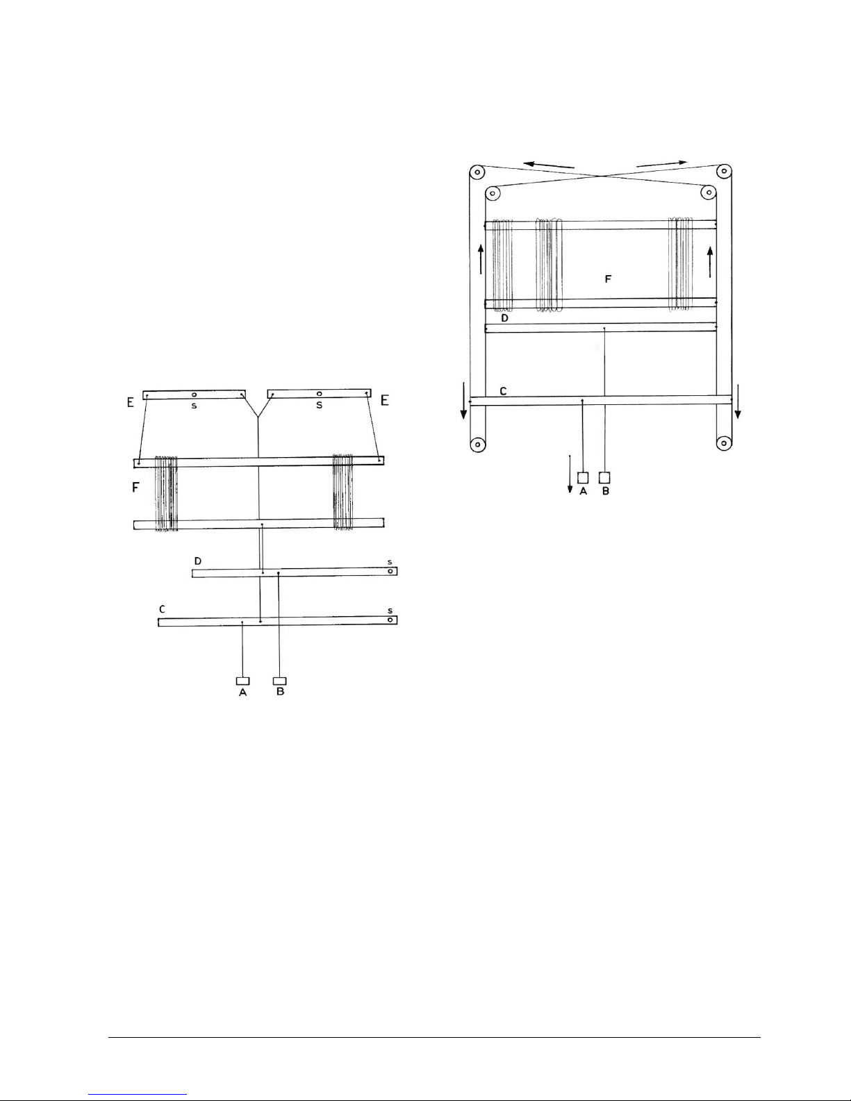
The moving breast beam allows the shafts to
move more easily in their opposite directions.
Looking at the diagram that shows the loom
from the side, you will see that a shed is giving
the warp a kind of parallelogram shape.
Imagine, the warp is made of inelastic material,
like metal wire, you will understand that making
a shed is only possible if the distance between
breast beam and back beam becomes smaller.
When this distance is fixed, as it is on other
looms, the shed depends completely on the
elasticity of the warp. When the shed becomes
wider, the tension on the yarns increases
(enormously, in case of a less elastic warp).
That causes heavy treadling and may damage
the warp.
The moving breast beam is held by springs,
adjustable to give your warp the tension needed
for your project. Besides improvement of the
shed and protection of the warp, the springs
guarantee exactly the same warp tension each
time you have to advance the fabric.
The Texsolv system
Texsolv cord and heddles are Swedish
products, crocheted out of polyester yarn.
Cotton heddles have the advantage of being
silent in use. Metal heddles, flat or wire, have
the advantage of having open eyes. Texsolv
heddles combine these features. A bundle of
Texsolv heddles is a continuous line of 100
heddles folded into a zigzag. Each bundle is
fastened in four places. These ties make it easy
to pass the shaft bars through the upper and
lower loop of the heddles. Do not remove the
ties from the bundles, until the heddles have
been slipped onto the shaft bars or the loops of
the bundles are inserted by sticks, to protect the
heddles from becoming entangled.
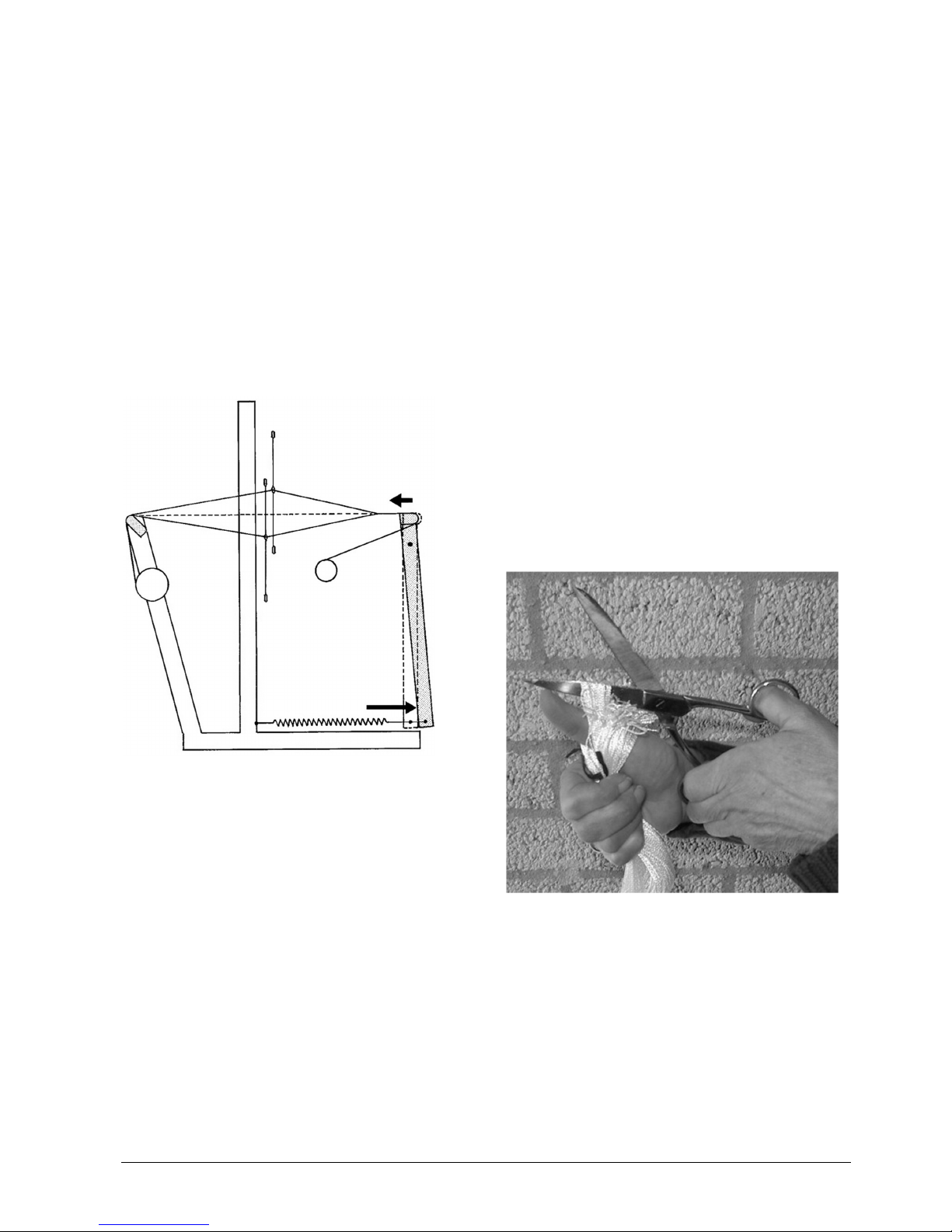
If you need to remove heddles from a shaft, first
tie them as they were originally. Use a pair of
sharp scissors to cut the heddles apart.
Texsolv cord consists of two cords, which are
connected every 12 mm, forming loops in
between. If needed, the cord should be cut
between two loops. To prevent unraveling, the
ends should be singed. Be careful not to overdo
the melting and be aware that melted polyester
is very hot and will burn the skin.
By mentioning the first or last loop in these
instructions, the loop is meant, next to the one
where the cord is cut, because when that loop
remains after cutting, it has no strength and
should not be used.
3
Spring assembly tips and information
Barrel nuts
For the assembly of the looms, we use barrel
nuts and bolts or threaded ends to connect two
parts. These cylinder shaped nuts have a slot
on one of the flat sides. Always insert the barrel
nut into the wooden part, so that the slot in the
barrel nut is visible. The slot shows the direction
of the threaded hole in the nut. With a flat
screwdriver you can turn the barrel nut so that it
is positioned properly to catch the bolt. If you
have a problem inserting the bolt into the barrel
nut, try turning the barrel nut 180 degrees. This
usually helps.
Carriage bolts
In other locations, we use carriage bolt to
assemble wooden parts. These bolts have a
square enlargement (neck) under the bolt head.
When you tighten the nut on the bolt, this
square neck locks into the wood to prevent the
bolt from turning. In some instances, you will
notice, that the bolt is just a little too short for
assembly with the washer and nut. We advise
you to put the nut on the bolt without the
washer, and then tighten the nut sufficiently, so
that the square neck pulls into the wood. At this
stage, unscrew the nut, install the washer and
then replace and secure the nut again, tightly.
Alternatively, you can carefully tap against the
bolt head with a hammer, until the bolt head is
secured into the wood.
Washers and spacers
For the proper operation of the loom, it is very
important that you follow the correct assembly
sequence of the bolts, washers and spacers.
Please carefully follow the instructions.
To help you, we have assembled all the
washers and spacers in the hardware bags in
the right sequence.
Wood screws
Where wood screws are used, we have pre-
drilled holes in the wood. The screws will cut
their own thread into these holes. Please note
however, that the screws are very sharp, and
will cut into the full wood outside the pre-drilled
holes, if you miss the pre-drilled hole during
assembly. However if this happens, you will
notice that after a couple of turns, it becomes
very hard to turn the screw. There is even a
chance that the screw will twist off. Moreover,
the parts will be assembled in the wrong
location.
If you have to assemble and disassemble the
loom several times, make sure that the wood
screw turns in the same thread again which
was cut the first time. If you do not follow this
instruction, the hole in the wood will become too
large for the screw. To find this screw thread,
turn the screw anti clock wise, until you "feel"
the screw "drop" into the threaded part in the
wood.
Tools
All parts used for the loom are metric. To
facilitate the assembly, we have included two
wrenches (10 mm for M6, 13 mm for M8), a
socket-head screw wrench and a pz2 cross
head screwdriver (not a Phillips head!).
4
List of parts
In box A:
Assembled middle part and a second box
containing, see picture:
1. 10 treadles
2. 2 beater supports (L=R)
3. 2 floating arms (L=R)
4. brake handle
5. 2 base sides (L+R)
6. 2 middle side pieces (L+R)
7. 2 top side pieces (L=R)
8. 2 warp beam supports (L+R)
9. locking pin
10. brake disc
11. cloth beam lever
12. beater handle
Not shown on the picture:
−hardware bags 1, 2, 3, 4, 5 and extra.
−54 long and 54 short tie-up cords for the
treadles.
−8 x 100 Texsolv heddles 39 cm.
In box B:
•lower reed holder
•upper reed holder
•cloth beam
•warp beam
•breast beam
•back beam and foot rail (attached to the
middle part in box A)
•shelf bottom
•reed (attached to the lams in Box A)
•2 apron bars
•2 cross sticks
•16 warp sticks
5
Assembly of the Spring
Place the already assembled middle part of the
loom, with its black buffers on the floor. Don’t
worry about the look of the top side pieces; they
are attachments to keep parts in place and will
be replaced during assembly.
Open hardware bag 1:
−a pz2 cross head screwdriver
−wrenches 10 en 13 mm
−socket-head screw wrench
−2 buffers
−2 screws 4 x 25 mm
−4 threaded ends M6 with a socket nut and a
barrel nut
−6 screws 5 x 50 mm
−bracket
−2 carriage bolts M6 x 100 mm with washer
and wingnut
−2 screw eyes
Screw the buffers onto the bottom side of both
base side pieces.
Mount the base and the middle side pieces onto
the middle part:
These rails are marked A, B, C and D, which
indicates where they are to be mounted onto
the middle part.
Unscrew the barrel nuts from four of the
threaded ends, but leave the socket-head nuts
on. Insert these threaded ends from the back
side through the holes in the middle part, where
the side pieces have to be assembled.
Insert the barrel nuts into the holes of the side
pieces.
The barrel nuts have to face the inside of the
loom.
Fasten the side parts with the socket-head
screw wrench.
6
Replace the top side pieces one by one:
Remove the two screws that hold the front rail.
Unscrew the socket-head nut and remove the
side piece. If the threaded end remained in the
barrel nut, take it out and take the barrel nut out
too.
Insert the barrel nut into the new top side piece
and assemble it in the reversed sequence, the
barrel nut facing the inside.
Screwing the side piece to the front rail it is
important to find the thread that is cut in the
hole the first time: Lift the front rail and find its
hole with the tip of the screw. Now turn the
screw anti clock wise while giving some
pressure. You will feel and hear when the screw
falls in the original thread and you can screw it
in, which should easily.
Repeat the procedure at the other side of the
loom. Slip the shelf bottom into the slot of the
front rail (you may need to loosen the screws at
the side pieces one turn).
Slip the shelf bottom into the slot of the front
rail. You may need to loosen the screws at the
side parts one turn.
Fasten the shelf front to the top side pieces,
using two of the 50 mm screws.
7
Assembly of the back section of the loom
Take the warp beam, the back beam and the
two warp beam supports and place them
together as shown on the picture. Insert the
shaft of the warp beam through the right
support and slide the left support onto the other
end of the warp beam.
Attach the supports to the back beam with the
remaining 50 mm screws. At the right side you
have to use these screws to attach the metal
bracket.
Screw the two 4 x 25 mm screws a few turns
into the main uprights at the level of the holes in
where the back part will be attached. The
uprights are identical so you will find one pilot
hole at the inside and one at the outside of the
loom.
Place the back part in its location by inserting
the polyurethane dowels into the holes at the
rear of the loom.
Secure the polyurethane dowels by screwing
the screws completely into the uprights, while
holding the back part in a position that let the
dowel in completely.
8
Take the two carriage bolts with washer and
wing nut and secure the back part as shown on
the picture.
When the loom is not in use, you can fold the
back part of the loom after removing the wing
nuts and washers again.
Screw the two screw eyes into the pilot holes at
the backside of the warp beam supports. If you
are used to leaving the lease sticks in the warp,
attach them to these eyelets.
Assembly of the foot rail and treadles
Open hardware bag 2:
−80 screws 4 x 17 mm
−4 screws 5 x 50 mm
−6 screws 6 x 70 mm
−5 axles Ø6 x 122 mm
−5 nylon spacer bushings
−6 axle support blocks
Screw the small screws into eight holes of each
treadle, so far that the screw heads protrude
approximately 5 mm (3/16”) from the wood. The
thread of the screws should just disappear into
the wood.
Use the eight holes closest to the end of the
treadle; the other four holes are to be used for
an extension to twelve shafts.
Place the foot rail upside down (pilot holes up)
on the floor in front of the loom.
Assemble the treadles onto the foot rail. The
screw heads on the treadles should point to the
right.
Slide two treadles with a nylon bushing in
between on each axle. Use the axle suspension
blocks and the big screws to assemble these
pairs of treadles to the foot rail. On each side,
one pilot hole on the foot rail should not be
used, unless you are assembling four more
treadles of an extension to twelve shafts.
9
Turn the foot rail upside up again and connect it
with the four remaining screws to the base side
pieces.
Mounting the floating arms
Open hardware bag 3:
−2 carriage bolts M8 x 60 mm with big
washer, bushing, small washer and cap nut
−7 screws 4 x 17 mm
−2 spring with a piece of Texsolv cord
−2 short Texsolv cords
−1 ratchet for the cloth beam
−1 screw 4,5 x 20 mm round head
−8 beam cords.
Take the wooden posts, recognizable for the
steel rod at the end. These floating arms will
hold the moving breast beam.
Tap the carriage bolts into the holes.
Slide the large washer and spacer bushing,
over the carriage bolt and attach the floating
arms at the inside of the middle side pieces of
the loom.
Use the small washers and cap nuts to finish
the assembly by strongly tightening the cap
nuts.
Screw four of the small screws into the pilot
holes at both sides at the bottom of the floating
arms and a small screw at the inside of the
base side pieces. The heads of these six
screws have to protrude about 5 mm (3/16”).
Hook on the springs to the screw eyes on the
back at the top of the middle part.
Bring the attached cords down through the
screw eyes at the bottom of the main upright
and lead them along the roller.