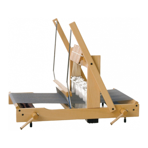
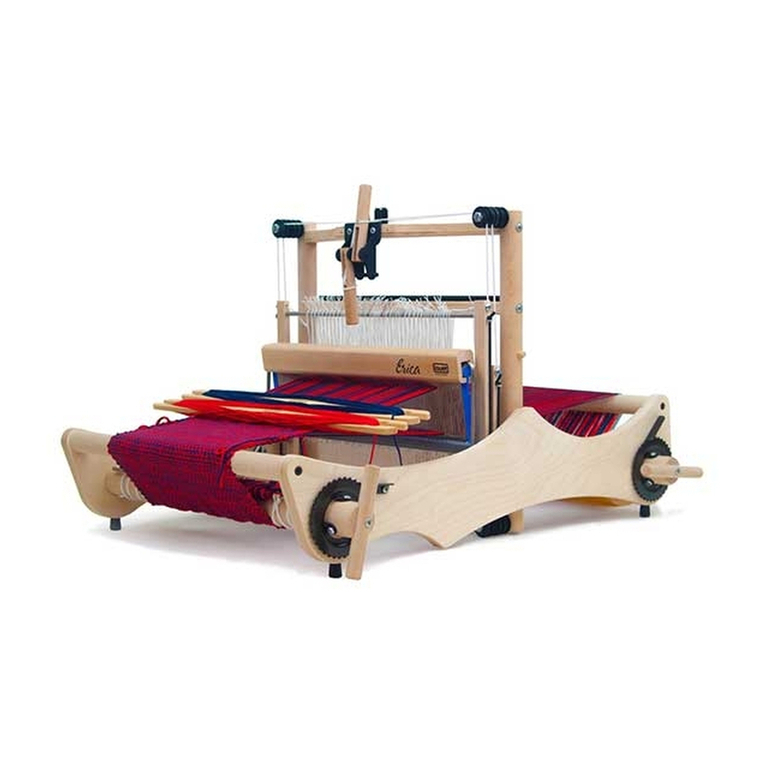
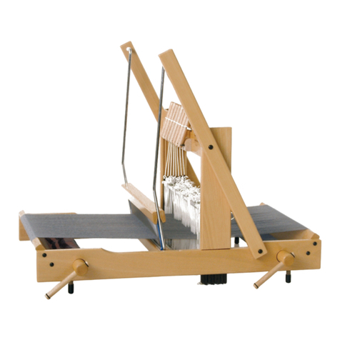
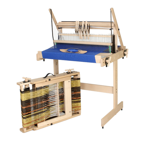
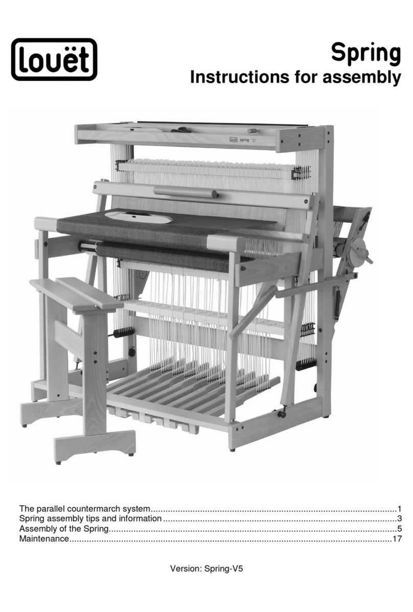
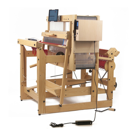
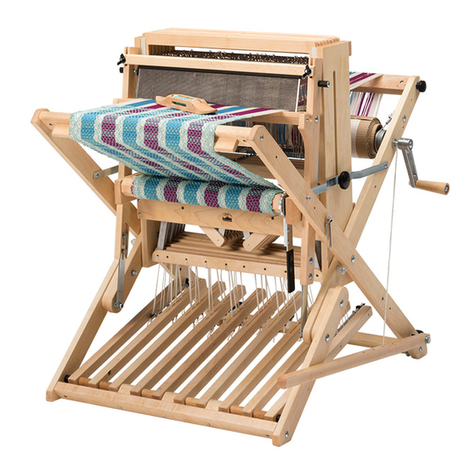
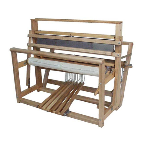
Louet David-III Assembly instructions

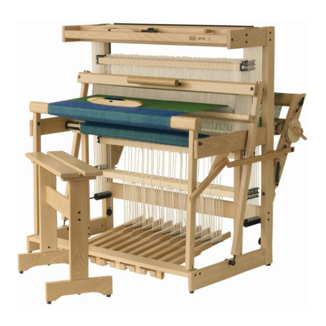
David III
Instructions for assembly
Assembly tips and information.........................................................................................................2
Instructions for assembly.................................................................................................................4
Weaving tips and information ........................................................................................................24

2
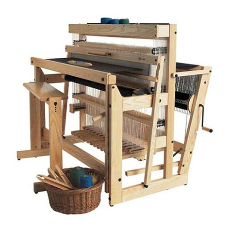
Welcome to your new David III loom
We know you’re going to love your new David! Louët is dedicated to bringing you the most comfortable and
enjoyable weaving experience. This manual provides you with step-by-step assembly instructions.
David III, the third generation David looms from Louët has been improved in many ways. The mechanical method
of making the shed has also been improved: The shaft height is more precise and easier to adjust and the
progressive shed has been improved by modifying the tie-up method. The tie-up to the treadles is the same as the
David II; only the shafts being pulled downward are tied, but the shed of the David has similarities with a counter
march shed.
Unique shaft movement system
In the rest position, all shafts and therefore the entire warp are pulled up by springs. Depressing a treadle pulls
down the attached shafts and with them part of the warp. When the treadle is pressed, the springs of the
attached shafts are stretched. More force is required as you stretch a spring, however with the David, that extra
force goes through the unique cams that during their rotating movement ensure that that force decreases as the
shafts continue down. You will notice this half way through the treadle stroke. The result is that in their highest
position, shafts are pulled up considerably and when you depress a treadle you notice the opposite of what you
would expect: The further you push on a treadle, the lighter it gets and the weight of your leg is sufficient to keep
the shed open.
The David has the shed of a counter march, but not the disadvantage of double tie-ups (all treadles to all shafts).
Moreover, the tie-ups are easy to attach: The cords remain permanently on the lams and can then be moved
above the treadle, where you then only have to hook the cord onto the screw head.
Overview hardware types and assembly tips and information
Barrel nuts:
For the assembly of the looms, we use barrel nuts and bolts to connect two parts. These cylinder-
shaped nuts have a slot on one of the flat sides, that show the direction of the threaded hole in
the nut. Always insert the barrel nut into the wooden part, so that the slot in the barrel nut is
visible. With a flat head screwdriver you can turn the barrel nut so that it is positioned properly
to catch the bolt. If you have a problem inserting the bolt into the barrel nut, try turning the
barrel nut 180 degrees, which usually helps to resolve the issue.
Carriage bolts:
In other locations, we use carriage bolts for assembly. These bolts have a square
enlargement (neck) under the head. When you tighten the nut on the bolt, this square
neck locks into the wood to prevent the bolt from turning. In some instances, you will
notice, that the bolt is just a little too short for assembly with the washer and nut. To
resolve this, screw on the nut without the washer to pull the square neck into the wood.
Now unscrew the nut, install the washer and then replace and secure the nut again,
tightly. Alternatively, you can tap against the bolt head with a hammer, until the bolt
head is secured into the wood.
Lag bolts:
These are bolts with a wood thread, but with the hex head of a regular bolt.
Wood screws:
Where wood screws are used, we have pilot holes in the wood. It is important to position the screws in the pilot
holes for proper assembly and operation of the loom. Because the screws are sharp, they can unintentionally cut
into the wood if used outside of the pilot hole. A screw that is very difficult to turn is usually a sign that you have
either mis-positioned the screw or are using the incorrect size. Go back and check the hardware to see if you have
selected the wrong screw for that particular assembly.
When re-inserting a screw that has been removed, it is important that the screw returns to the thread it cut
earlier. Otherwise, the connection would lose its strength after a few times. Finding the old thread is easy: Push
the screw into the hole, turning it counterclockwise. Stop when a light tap indicates that the screw “falls” into its
3
old thread. Now turn the screw clockwise again and you will notice that you are in the right position by the ease
of screwing.
Washers and spacers:
For the proper operation of the loom, it is very important that you follow the correct assembly sequence of the
bolts, washers and spacers. Please carefully follow the instructions.
Texsolv cord and heddles
Texsolv cord and heddles are a Swedish product, crocheted from polyester yarn. Texsolv heddles combine the
advantages of cotton heddles and steel heddles: they are silent and have an open eye. The bundles of 100
heddles consist of a zigzag folded double cord. The double cord is locally connected, forming the heddles. To
avoid tangling, do not remove the straps from the bundles until the shaft slats are passed through or anything
else through the loops of the bundle.
As an accessory we supply a heddle helper, adjustable for different heddle
lengths, on which you can divide heddles into bundles of smaller numbers. Tie
these smaller bundles off again in 4 places, before removing them from the pins
of the heddle helper.
You can cut the heddles apart by cutting all the loops that connect
them at both ends of the bundle.
Texsolv cord
Texsolv cord consists of two cords, that are connected every 12 mm, forming loops in between. So the cord is a
chain of loops. This makes tying the loom easy and afterwards adjustment unnecessary.
The Texsolv cords that come with the loom have already been cut to the correct length. The cuttng was done in
between two loops in the cord. When referring in this instruction to the first or last loop in the cord, always the
loop is meant next to the one where the cord has been cut, that one has no strength and should not be used.
If you cut texsolv cord yourself, prevent unraveling by singeing the ends with a lighter. Be careful not to overdo
the melting and be aware that melted polyester is very hot and will burn the skin.
Tools:
All parts used for the loom are metric. To facilitate the assembly, we have included two wrenches (10 mm for M6,
13 mm for M8), two allen keys (4 and 5 mm), a Pz2 cross head screwdriver (not a Phillips head!) and a Pz2 bit. In
addition to these tools, you will need a hammer, scissors and a battery hand drill which saves a lot of work when
screwing into the treadles.

4
Assembly of the frame:
Open box A:
Hardware bag 1 and 2 (The picture shows one
bag that contains both –bag 1 is tools only)
Open hardware bag 1: screwdriver Pz2 and
wrenches 10 and 13 mm.
Open hardware bag 2:
1.
2 main uprights (L=R)
HL0020
2.
2 front posts (L=R)
HL0021
3.
warp beam supports
(left)
HL0022
3.
warp beam supports
(right)
HL0023
4.
Side rail (left)
HL0024
4.
Side rail (right)
HL0025
5.
2 beater uprights (L=R)
HL0026
6.
Handle of the beater
HL0019
7.
10 treadles
HL0027
8.
Steel axle for the
treadles Ø6 x 670 mm
(David 70)
BZ0026
9.
Brake Handle
HL0028
10.
Cloth beam lever
HL0029
11.
Lams
BZ0027
12.
Hardware Bag 2
BZ0028
1.
2 steel shafts Ø8 x 74 mm
BZ0016
2.
Hinge Hook, M8 w/ M8
barrel nut (BN0017) and
washer (BW0004)
BZ0017
3.
8 M6 x 120 Bolt with M6
barrel nut (BN0015) and
large M6 washer
(BW0003)
BB0053
4.
Large Pawl
BZ0018
5.
M6 Large washer
BW0003
6.
M6 small washer
BW0002
7.
M6 x 25 mm bolt
BB0001
8.
2 bolts M6 x 130mm
BB0054
9.
M6 Large washer
BW0002
10.
4 screws 5 x 55mm
BS0068
Unlabelled –18 dowels 8 x
25mm
BZ0019

5
Open box B
Take the lower side rails from box B. These here in the
picture are for the 90 or 110 cm David; on the David 70
they have bearings for the lams.
Insert the M8 barrel nuts into the side rails. These are
longer than the thickness of the wood and you let them
protrude with their slot side on the side where the
holes for the smaller (M6) barrel nuts are also located.
Screw the regular nuts half way onto the hooks. Then
slide a washer on, screw the hooks into the barrel nuts
and secure them with the nut, holding the hook
perpendicular to the rail, as shown in the right picture.
Take the side rails from box A and mount the pawl on
the right side rail: Place the small 6 mm washer on the
6x25 mm bolt, then the pawl and finally a larger 6 mm
washer. Screw the bolt with these parts into the side
rail and then back off a little, just enough to allow the
pawl to rotate freely.
1.
Footrail –David 70
HL0001
1.
Footrail –David 90
HL0002
1.
Footrail –David 110
HL0003
2.
Lower cross rail (with felt
buffers) David 70
HL0004
2.
Lower cross rail (with felt
buffers) David 90
HL0005
2.
Lower cross rail (with felt
buffers) David 110
HL0006
3.
Lower side rails (L=R)
HL0007
4.
Raddle covers
WA0419
5.
Harness Castle David 70
HA0001
5.
Harness Castle David 90
HA0002
5.
Harness Castle David 110
HA0003
6.
Hinge Rail David 90/110
HL0008
7.
Heddles –280 –
800/1000/1200
WA0215
8.
Hardware Bag #4
BZ0020
9.
Brake Drum Disc
HL0009
10.
16 Warp Sticks David 70
WR0120
10.
16 Warp Sticks David 90
WR0121
16 Warp Sticks David 110
WR0122

6
Tap 2 dowels into the outer holes at both ends of the
four side rails. This leaves 2 dowels that you will need
later during assembly.
Attach the side rails to the main uprights: press the side rails with its dowels into the uprights, insert a barrel nut
into the side rail, a bolt 6x120 mm with washer through the upright and screw the connection together firmly. All
parts of the loom sides are the same on the left and right, except for the top side rails; they are a mirror image.
The pictures show in which position the side rails must be mounted on the upright. This way the holes of the M6
barrel nuts will be on the inside of the loom sides.
Insert the Ø8x74 mm shafts into the top of the front posts; use the hammer if
necessary.
Insert the assembled part with the side rail dowels into the holes of the
front posts and make the connections in the same way with bolts,
washers and barrel nuts.

7
Take the bottom crossbar from box B. It can be recognized by the sloping side with the 10 felt buffers. Connect
the long uprights of the loom sides by screwing this crossbar between them using the 4 screws 5 x 55 mm. The
slanted side with the felt buffers should be at the bottom and in such a way that they will later be flush with the
ascending treadles, so the cross rail faces with the wider side the front.
Place the pre-assembled castle section with the dowels on top
of the uprights and mount it with the two M6x130 mm bolts and washers. The barrel nuts are already pre-
installed in the uprights.
Assembly of the foot rail and treadles
Open hardware bag 3:
1
Spacer 33 mm
2
13 nylon bushings Ø6 -10
x 30 mm
BA0007
3
6 big screw eyes Ø10 mm
BS0068
4
Bit Pz2
BS0019
5
Bag with 80 screws 3,5 x
20 mm
BZ0020
6
10 screws 5 x 55 mm
BZ0021

8
Take the treadles from box A and screw the 3.5 x 20 mm screws into the row of 8 holes in each treadle.
The holes are located in a groove on one side of the treadle. The screw heads should stick out about 4 mm
(5/32“), so about 1 mm out of the treadle groove. This will prevent the cords from being caught by adjacent screw
heads when they hang loose.
If you have an electric hand drill, that saves a lot of time. You will find a drill bit for this in the hardware bag. First
screw in the screws a few turns with the screwdriver, then with the drill to approximately the depth and finally
adjust the depth again with the hand screwdriver.
Take the foot rail from box C and screw in the 6 screw eyes.
Insert the screwdriver through the eye to gain leverage if
needed. With a David 90 or 110 cm, the outer holes are not
used; these foot rails are also used for the Spring 2 loom,
which must accommodate 14 treadles, hence the extra
holes. The smaller holes near the two holes at the ends of
the foot rail are for locking the axle of the treadles. Screw
the eyes into the wood until they stick out 33 mm. You can
check that with the 33 mm spacer. The eyes should be
neatly perpendicular to the foot rail. A half turn results in a
small difference in height, but that is easily accommodated
when assembling the treadles and the axle.
Lay out the 10 treadles so that the sides with the screw
heads face the center; with the left 5 treadles the screw
heads are on the right and with the right treadles they are
on the left. You can inspect the treadles and select the best
side of a treadle facing up and the screw heads determine
whether the treadle is positioned on the left or right of
center.
Take the axle for the treadles from box A - Ø6 x 670 mm.
Insert a nylon bushing Ø6-10x30 mm through the first eye.
Insert the axle through the bushing, then add a treadle,
followed by another bushing and then a second treadle.
Repeat this process for each eye while constantly pushing
the axle through further and further.

9
Take 2 screws 5 x 55 mm and insert them through the 2
remaining 30 mm bushings. Mount those bushings at both
ends of the treadle axle in the foot rail. The axle is now
locked in and the treadles are exactly in place.
Turn the foot rail over and place the assembly between the front posts of the David.
Screw the foot rail between the two front posts using the
remaining 5 x 55mm screws. This works best if you screw
them in a few turns first on one side, then screw them all the
way in on the other side and finally the first two screws again
completely.

10
Installing the shafts and the lams
Contents of hardware bag 4:
With the David 70, the lams hinge in the lower side rails, as
with the previous version of the David. With the David of 90
and 110 cm weaving widths, the lams now hinge in the hinge
rails from box B.
For a David 90 or 110, open hardware bag 4 and take out the 2
screws 5 x 50 mm. Screw the rails for the lams onto the back
cross rail; the nylon bearings face inward.
Press a clip on the end of a lam. This is easiest if the clip is on
the table and you press the end of the lam into the opening.
Then slide a threaded eye with cord on it and then another
clip. Move all three to the middle of the lam. Sliding one by
one is easier than all three at the same time.
1
8 lam cords with
threaded eye M4
(BS0078) and nut M4
(BN0003)
BZ0021
2
80 tie-up cords for the
treadles, 16 cm long
BZ0023
3
Bag with 34 screw hooks
BS0005
4
Retaining clips
BA0008
5
2 screws 5 x 55 mm
BS0068

11
Slide 5 (the picture shows only 4) tie-up cords for the treadles on both ends of each lam, with a cord loop and not
with a ½ hitch knot.
Assemble the lams by placing their ends into the nylon bearings
of the hinge dowels, or of the lower side rails for a David 70.
Screw the screw hooks into the holes at the ends of the shaft
bars. The picture shows how deep they should be screwed in.
Cut the loops at the ends of the heddles with sharp scissors (see
page 3).
The David 70, 90 and 110 have 8, 10 and 12 bundles of 100
heddles respectively. It is useful to put a bundle of 100 heddles
on each shaft, unless you already know that you will need more
and/or a different distribution of heddles for your first project.

12
At the bottom of the castle section, cords stick out from which
you will hang the shafts. On the left, a blocking pin is in place,
making it easy to find the correct cord sequence. On the right
side of the cams you have to pay closer attention to the correct
sequence while hooking on the shaft bars.
Hang a bundle of heddles on a shaft bar and hook the shaft bars
hooks onto the cord on each side. Remember to use the cord
loop next to the loop where the cord is cut.
Take a second shaft bar, insert it through the bottom opening in
the bundle of heddles (make sure that the bundle is not twisted)
and hook the ends of the cord of the appropriate lam onto the
hooks of the shaft bar.
Now you can remove the twist ties from the heddles and spread
the heddles over the shaft.
If it turns out that not all the heddles have been cut (at the top)
cut any that may have been missed.
Slide the connection between the lam cord and the lam to the
exact center of the David, which is indicated by a mark on the
crossbar.
Repeat the described operations for all eight shafts.

13
Then tie on a number of treadles, but in such a way that all lams
on both sides of the middle (the connection to the shafts) are
connected to at least one treadle.
Push the shafts down slightly and pull the locking pin out of the
left side cords.
If you want to add heddles or remove heddles from shafts later
on, insert the pin again through the cords you just took them out
of. This prevents the cord of the shaft that you loosen from
falling.
You also use the locking pin later on, to take the tension off the
shafts, but then by blocking the cams. The photo shows how to
block the cams with the pin; push the shafts down so far that you
can put the pin through (along) them this way.
Adjusting the height of the shafts
Remove the locking pin.
The horizontal position of the shafts is already set with the
length of the cords connecting the cams to the left ends of
the shafts. If necessary, you can correct the horizontal
position with the screw that secures the cord to the cam.
Because the average height of the shaft remains the same,
one side drops when the other side goes up while adjusting.

14
The shafts are now pulled up by the springs via the cams in
the castle section. The lams and tied-up treadles are also
pulled up with this, until those treadles rest up against the
cross rail. The shaft height is therefore determined by the
distance between treadles and the shafts and you can
adjust this distance precisely with the nut on the screw eye
in the middle of the lam. They are hard to turn if there is
tension on the lam cords, but if you pull these cords down,
the nut turns easily. When you release the lam cord, it
pushes back against the nut; the cord secures the nut in the
adjusted position.
Adjust the shafts in ascending height from front to back: The space between the bottom of the castle and the top
of the shaft bar should be 8 cm (3 1/8”) for shaft one and 6 cm (2 3/8”) for shaft 8. Use the spacer from hardware
bag 3 to properly measure and adjust on both front and back.
Screw the remaining screw hooks on both sides into the back of the
castle. When setting up a warp, you attach the lease sticks to these
hooks.
Assembly of the warp beam section
Open hardware bag 5:
1
2 Polyurethane connectors
BZ0024
2
4 screws 3 x 20mm
BS0058
3
3 thread eyes M6 x 50 mm –
1 also contains 2 small
washers (BW0002), 1 large
washer (BW0003) and M6
barrel nut (BN0015
BS0010
4
2 screw eyes 6 mm
BS0006
5
bag with 2 dowels 8 x 25
mm, 2 large washers 6 mm,
2 screws 5 x 50 mm and 2
clips 6 mm
BZ0025

15
Insert the flexible pu pieces into the warp beam supports
and secure them with two of the small screws.
Place a large washer on a threaded eye and insert the threaded eye through the hole at the tip of the warp beam
support. Now press a clip on the end of the threaded eye. Push it further on the thread until the threads just
protrude. You can use the washer on the third screw eye to slide the clip further over the screw thread into the
hole.
Open box C:
The picture shows from the left to the right:
1
Top beater bar –70
HL0010
1
Top beater bar - 90
HL0011
1
Top beater bar - 110
HL0012
2
Bottom beater bar -70
HL0013
2
Bottom beater bar - 90
HL0014
2
Bottom beater bar - 110
HL0015
3
Warp beam - 70
HL0016
3
Warp beam - 90
HL0017
3
Warp beam - 110
HL0018
4
Cloth Beam - 70
HL0030
4
Cloth Beam - 90
HL0031
4
Cloth Beam - 110
HL0032
5
Breast Beam - 70
HL0033
5
Breast Beam - 90
HL0034
5
Breast Beam - 110
HL0035

16
6
Shelf - 70
HL0036
8
Lease Sticks –70
WR0152
6
Shelf - 90
HL0037
8
Lease Sticks –90
WR0131
6
Shelf - 110
HL0038
8
Lease Sticks –110
WR0132
7
Back Beam - 70
HL0039
9
16 Warp Sticks - 70
WR0120
7
Back Beam - 90
HL0040
9
16 Warp Sticks - 90
WR0121
7
Back Beam - 110
HL0041
9
16 Warp Sticks - 110
WR0122
10
Reed –40-10 70-(WA0248), 90-(WA0257), 110 –(WA0266)
Take the back beam and the warp beam from box C. One end of the back beam has 3 holes for the barrel nut
connection and 2 dowels. This matches the holes in the right warp beam support.
Tap the 2 dowels into the right warp beam
support with a hammer.
Slide the back beam onto the dowels and make the barrel nut connection with the threaded eye that has 3 small
and 1 large washer. Tighten the eye firmly (see page 17), the eyelet is also used to connect the brake cable.

17
Slide the warp beam with its long axle through the warp beam support that you have just assembled. If you have
also purchased a 2nd warp beam, now would be a good time to add it, to prevent having to un-assemble the back
beam section later on.
Slide the other warp beam support onto the other end of the warp beam and screw it to the back beam with 2
screws 5 x 50 mm.
Lift the assembled warp beam and insert the flexible pieces one by
one into the holes of the main uprights.
Tighten the threaded eyes into the pre-assembled barrel nuts in the
uprights. If necessary, insert the screwdriver through the eye to
tighten them.

18
You use the other two small screws to secure the flexible pu pieces
into the uprights. Because the two uprights are the same, the screw
in the picture is on the outside, but with the other upright it is on
the inside of the upright.
Screw the remaining screw eyes into the back of the warp
beam supports.
Assembly of the cloth beam and attaching the beam cords
Hardware bags 6 and 7 come later; these bags are also used
for our Spring loom, but the order of assembly is different for
the David loom.
Open hardware bag 8:
1
1 ratchet wheel
BZ0029
2
6 texsolv beam cords, 120 cm long
BZ0030
3
1 texsolv cord, 37 cm long
BZ0031
4
4 screws 4 x 21 mm
BS0062
5
9 screws 4 x 20 mm
BS0028

19
Take the cloth beam from box C.
Place the ratchet wheel on the long axle of the cloth beam; the X-marked side of the ratchet wheel should face
the beam. Fasten the ratchet wheel with the 4 screws 4 x 21 mm, these are the screws that are a little longer.
Take the cloth advance lever from box A, slide it on the axle against the ratchet wheel and place the cloth beam
on the loom.
Screw a 4 x 20 mm screw (one of the 9 screws that are left) in the inside of the right side rail; let the head
protrude 5 mm. Hook the short texsolv cord onto this screw head, guide it around the handle of the cloth advance
lever and hook the other end onto the screw head as well. In this way, you determine how high the handle will
hang by which cord hole that you choose. Afterwards you can see what is a convenient height for you when
sitting at your loom.
Screw the remaining 8 screws 4 x 20 mm into the cloth and warp beams, so far that their heads barely protrude
beyond the beam surface. You can now easily attach the beam cords to the screw heads.

20
Assembly the warp beam brake
Open hardware bag 6:
Attach the handle to the brake disc with the Allen bolt: Insert the Allen
bolt through the hole from the side where there is a slot in the disc.
When tightening, the bolt cuts a thread into the wood of the handle.
Tighten the bolt until the handle can just turn properly.
Take the 5 mm shaft and insert it through the hole in the
axle of the warp beam so that it protrudes equally on
both sides. Next, slide the brake disc onto the axle until
you have pushed the 5 mm shaft into the slot of the
brake disc.
1
Tension Brake spring T248
BN0009
2
Brake Cable
BZ0032
3
1 steel shaft Ø5 x 112 mm
BZ0033
4
Handle for the brake disc
BZ0035
5
Allen bolt M6 x 60 mm
BB0007
6
Eye hook bolt –for brake
BZ0034
7
Large Washer M6
BW0003
8
Steel Knurled Nut
BN0014
9
3 screws 5 x 30 mm
BS0042
10
2 screws 4 x 20 mm
BS0028
11
1 x carriage bolt M8 x 80 mm
BB0037
12
Large washer M8
BW0005
13
bushing 12 mm
BA0004
14
Bushing 33 mm
BA0006
15
2 small washers M8
BW0004
16
Cap Nut M8
BN0012
Other manuals for David-III
1
Other Louet Weaving manuals

Louet
Louet Jane Assembly instructions

Louet
Louet Kombo 40 4+4 User manual

Louet
Louet Spring Assembly instructions

Louet
Louet Kombo 70 4+4 User manual

Louet
Louet Spring User manual

Louet
Louet Delta User manual

Louet
Louet Megado Computer Dobby 2.0 User manual

Louet
Louet Erica User manual

Louet
Louet Erica User manual