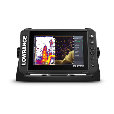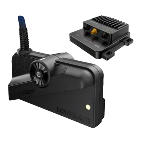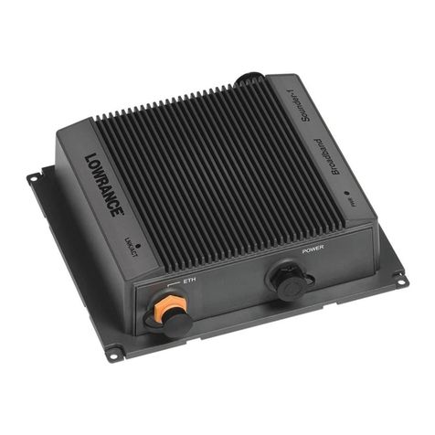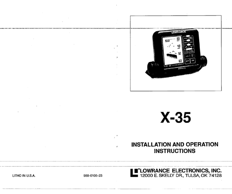
The Discrimination feature on Lowrance sonar units removes many
falsesignalsfromothersonars, acoustic and electrical sources, and
more.
FISHALARM-Analarm thatactivateswhenafishor
suspendedobject
isdetected.
FISH ARCH-A sonarwithgood resolution anddefinition candisplay
suspended targets as upside down"Vees"or arches. Thesesignals
aretypicallyfish, hence thename "Fish Arch". Seepage 20 formore
information.
FLUSH MOUNT -Atransducer that is installed withthebottomofthe
transducer flushwiththebottomofthehull.
GIMBAL BRACKET- A bracket usedto install a sonar unit perma-
nently. Thesonarunitcan rotate inthe bracket forthebestviewing
angle.
GRAYLINE Thifeatureshows the relative strengthof signals dis-
played
onthescreen. Signals weakerthan theGRAYLINE setting are
displayed inblack, strongertargets
aregray. Italsogivescluestothe
composftion ofthebottom. Inotherwords, youcantellifthebottom is
softorhard. Ahardbottom returns astrong signal causing a
widegray
line. Asoft,muddy
orweedybottom returns aweaker
signalwhichis
emphasizedwithanarrow
grayline.
IN-DASH - Asonar unit installed through a holein the boat'sdash.
Usually, thefaceofthesonar isflushornearly sowiththedash.
kHz- Kilohertz. Ameasurement offrequency. Your Lowrance sonar
operates at192Kilohertz. (192,000cyclespersecond).
LCD-Liquidcrystal display. Thescreen or display ofaLiquidCrystal
Graph sonarinstrument.
LCG -Liquid Crystal Graph.
NOISE -Any undesired signal. Electrical noise iscaused by engine
ignitionssystems, radios, etc. Acoustic noise iscaused
bythe
vibration
of the engineor other mechanical sources. Noise appears on the
display as random dotsorlines.
NOISE
Minimize electrical noiseby routing thepowercable away fromother
possible sources ofelectrical interference. Oneofthelargest noise
generators isthe engine's wiring harnessthat runs fromtheengine to
the instrument panel. This harness usuallycontainsa wire for the
tachometer which radiatesRF (radiofrequency) energy. For best
results, keep the powerand transducer cablesawayfromthe engine
wiring. Also, bilgepump wiring can sometimes radiatenoiseso tryto
keeptheX-20's cables awayfromthosewires.
VHFradio antenna cables typicallyradiate RF energy
at higherpower
levels thantheengine'swiring harness. It isimportant tokeepthe X-
20's powerandtransducercables as faraway as possible
fromVHF
radio cables.
Ifinterference begins atslowboatspeeds, worsening astheboat
speed
increases, thena
probable
causeisacoustic noise,
orcavitation. This
noise isnot
electrical, but rather mechanically induced noisefromthe
transducer. Stop
theboat, puttheengineinneutral,
and increase the
Rpm. Ifthenoisedoesnot
increase onthe
display,
thenitiscavitation.
Usually,air bubbles passing over theface of thetransducercreate
acoustic noise. Thefasteraboattravels, themoreairbubblesincrease
andgenerate noiseonthe
display. Toeliminatethisproblem, readthe
transducer installation section
forpropermountingtechniques.
TRANSDUCER
Transducerinstallation instructions are packaged separately with the
transducer. Please readtheinstructions carefully
before
youinstallthe
transducer.
Periodically wash thetransducer's facewithsoapandwatertoremove
anyoil filmthat maycollect. Oil and dirt on theface will reducethe
sensitivity ormayevenpreventoperation.
Paint transducers on saltwaterboatswith a thin coat of anti-foulant
paint
toprevent organisms fromgrowing. Ifunchecked, barnacles and
othermarine growth willcauseadecrease inthetransducer's sensitiv-
ity. Donotuseametal based anti-foulant paintasitwill decreasethe
transducer's sensitivity. Thereare special anti-foulant paints specifi-
callydesigned fortransducers. They'rereadily
available atmostmarine
dealers
26 3
PDF compression, OCR, web-optimization with CVISION's PdfCompressor
