any setting, don‘t change after set-up procedure!
any setting, don‘t change after set-up procedure!
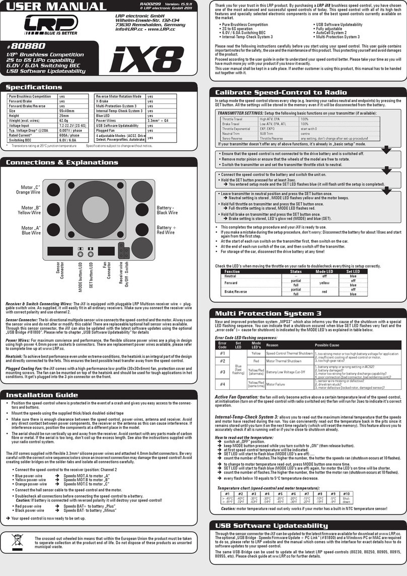
Setup the following basic functions on your transmitter (if available):
If your transmitter doesn‘t offer any of above functions, it‘s already in „basic setup“ mode.
sure that the speed-control is not connected to the drive battery and is switched off.
Remove motor pinion or ensure that the wheel
s of the model are free to rotate.
Switch the transmitter on and set the transmitter throttle stick to neutral.
-control to the battery and
ressed for at least 3sec using the supplied plastic screwdriver.
Leave transmitter in neutral position
and press the SET button once.
Neutral setting is stored , L
ll throttle on transmitter
and press the SET button once.
Full-throttle setting is stored,
and press the SET button once.
ke setting is stored, LED glows green
This completes the setup pro
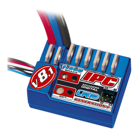
LRP IPC GENERATION+ series speed-control
• If you have made a mistake so far, don’t worry: Switch off the speed-control for about 10 seconds
• After the run, first switch off the speed-control, unplug the battery and then switch off the transmit-
again, first switch on the transmitter, then plug in the battery and switch on the
ys disconnect the drive battery from the speed-co
ntrol, if you are not using your model.
LED when moving your throttle stick and you will see if everything is setup correctly.
APC Adjustable Power Control
It is very easy to loose control of a model car on a slippery track surface if you are running a powerful
motor. The adjustable power control provides the solution. The unique LRP APC (Adjustable Power
Control) effectively prevents unwanted spins and slides, improves vehicle control and thus improves
your lap times and extends running times.
Adjusting the APC system:
• For maximum power - rotate the power potentiometer carefully to the right-hand stop using the
plastic screwdriver supplied.
• If your car tends to spin - you need slightly less power when accelerating. Rotate the power poten-
tiometer to the left until you can control your car during acceleration.
• If your car has a powerful motor and your speed control switches into temperature protection (over-
load protection) - rotate the power potentiometer about 1/3 of a turn to the left.
The APC function has no effect on the car’s maximum speed.
lti-Protection System, 3-way protection
he perfect protection against short-circuits (motor), overload and overheating. If your speed-control
faces one of these problems, the motor function will be shut-off for protection and the LED will flash.
The steering function will be maintained. Let everything cool down for a few minutes.
If the speed-control switches off frequently, either the used motor is too strong, the motor pinion is
too big or you are using full brake too often. You can improve this if you make additional cooling slots
series speed controls feature a fully proportional EMF brake which can
be applied very smoothly to maintain good grip on slippery surfaces. Thanks to the Advanced Digital
technology, it was possible to improve the brake feel of the
• Smooth, proportional braking
• Battery recharge during braking
If the braking power is too strong for your driving style and conditions, you can reduce it by adjusting
servo travel at the transmitter.
REPAIR PROCEDURES /
LIMITED WARRANTY
All products from LRP electronic GmbH (hereinafter called “LRP”) are manufactured according to the
highest quality standards. LRP guarantees this product to be free from defects in materials or work-
manship for 90 days (non-european countris only) from the original date of purchase verified by sales
receipt. This limited warranty doesn’t cover defects, which are a result of normal wear, misuse or
This applies among other things on:
Cut off original power plug or not using reverse polarity protected plugs
Receiver wire and/or switch wire damaged
Mechanical damage of the case
Humidity/Water inside the speed control
Mechanical damage of electronical components/PCB
Soldered on the PCB (except on external solder-tabs)
Connected speed-control with reversed polarity
To eliminate all other possibilities or improper handling, first check all other components and the trouble
shooting guide, if available, before you send in this product for repair or warranty. Products sent in for
repair, that operate perfect have to be charged with a service fee.
By sending in this product, you assign LRP to repair the product, if it is no warranty or Limited Lifetime
Warranty case. The original sales receipt including date of purchase needs to be included. Otherwise,
no warranty can be granted. For quick repair- and return service, add your address and detailed de-
scription of the malfunction.
Because we don’t have control over the installation or use of this product, we can‘t accept any liability
Because we don’t have control over the installation or use of this product, we can‘t accept any liability
for any damages resulting from using this product. Therefore using this product is at owner‘s risk. Our
for any damages resulting from using this product. Therefore using this product is at owner‘s risk. Our
limited warranty liability shall be limited to repairing the unit to our original specifications. In no case
limited warranty liability shall be limited to repairing the unit to our original specifications. In no case
shall our liability exceed the original cost of the unit. By installing or operating this product, the user
shall our liability exceed the original cost of the unit. By installing or operating this product, the user
accepts all resulting liability.
The specifications like weight, size and others should be seen as guide values. Due to ongoing technical
The specifications like weight, size and others should be seen as guide values. Due to ongoing technical
improvements, which are done in the interest of the product, LRP does not take any responsibility for
improvements, which are done in the interest of the product, LRP does not take any responsibility for
the accuracy of these specs.
With Limited Lifetime Warranty products, the warranty terms on the Limited Lifetime Warranty card
With Limited Lifetime Warranty products, the warranty terms on the Limited Lifetime Warranty card
• Package your product carefully and include sales receipt and detailed description of malfunc-
• Send parcel to your national LRP distributor.
• Distributor repairs or exchanges the product.
• Shipment back to you usually by COD (cash on delivery), but this is subject to your national LRP
distributor‘s general policy.
LRP IPC GENERATION+ series speed-control
stores every step when you press the
SET button. All the settings will be stored in the speed-controls memory even if the speed-control will
disconnected from the battery.
6. RADIO / SPEED-CONTROL SET-UP
Servo is working, no motor function.
Speed-control plugged in incorrectly
Plug speed-control in Ch 2
Overload protection activated
Allow speed-control to cool down
Check that brushes are moving freely
Send in product for repair
No servo and no motor function.
Speed-control plugged in incorrectly
Plug speed-control in with correct polarity
Replace components one by one.
Send in product for repair
Motor runs in reverse when accelera-
ting forward on the transmitter.
Motor connected incorrectly
Insufficient performance.
E.g. poor brake power, topspeed or
Motor pinion too big or gear ratio too long.
Use smaller motor pinion/shor ter gear ratio
Transmitter settings changed after set-up
Send in product for repair
Speed-control overheats or switches
Motor stronger than motorlimit or input voltage
Use only motors and batteries which are within
the specifications of the speed-control
Motor pinion too big or gear ratio too long.
Use smaller motor pinion/shor ter gear ratio
Drive train or bearing problems.
Check or replace components.
Model used too often without cool-down periods
Let speed-control cool down after every run
Motor never stops, runs at constant
Transmitter settings changed after set-up
Humidity/water in speed-control
Immediately unplug and dry speed-control
Send in product for repair
Motor suppressors not sufficient
Solder capacitors to motor
Receiver or antenna too close to power wires,
motor, battery or speed-control.
Receiver aerial too short or coiled up
See „Installation Tips“ and „Installation“
Receiver defective, too sensitive;
Transmitter defective, transmitter output power
Replace components one by one
Only use original manufacturers crystals
Check plugs and connecting wires
Transmitter batteries empty
Replace / recharge transmitter batteries
Transmitter antenna too short
Pull out antenna to full length
Speed-control looses settings
Receiver problem (especially with some 2.4GHz
Use a power capacitor on the receiver
