manuals.online logo
Brands
  1. Home
  2. •
  3. Brands
  4. •
  5. LUBRIQUIP
  6. •
  7. Lubrication System
  8. •
  9. LUBRIQUIP Trabon Series Operation manual

LUBRIQUIP Trabon Series Operation manual

©LUBRIQUIP,INC.,1963. Revised May 1996. All RightsReserved.
DESCRIPTION
In a Trabon Series-Flo System®, free flow of lubricant from the
pump through the transmission system and the bearings is
necessary. If any portion of this transmission system (a divider
valve, line fitting or any bearing) does not freely accept and
pass its portion of the lubricant a blockage has occurred. This
blockage will cause a higher than normal pumping pressure to
be developed by the pump. Depending on the application or
system design, this blockage with its resultant high pump
pressure will usually cause a complete loss of lubricant flow
into the total system and no bearing will be receiving lubricant.
The loss of flow due to a blockage is first indicated with the
higher than normal system pressure that is developed by the
pump as it attempts to overcome this blockage. This abnor-
mally higher pressure that is a result of a blockage is limited,
isolated, and signalled through the use of various performance
indicators, reset and relief, incorporated into the system
design.
Divider Valve —
A Series-Flo®type divider valve is a manifolded proportioning
device consisting of an inlet and end section plus a minimum of
three intermediate sections. The divider valve is manifolded
together with tie rods and nuts. A master divider valve is the
first divider valve downstream from the lube pump. A second-
ary divider valve is any divider valve receiving lubricant from
the master divider valve.
Intermediate Sections —
Intermediate sections (three or more required per manifold)
contain a piston specially fitted to that section, built in outlet
check valves and various passageways that, working with the
piston, meters and valves the flow of lubricant. See Figure B.
Intermediate sections may be manufactured to require one (1)
or two (2) lube outlets. Stamping located on the face of each
section will indicate (1) the style of divider valve section (MSP,
MX, etc.), (2) the discharge per piston stroke expressed in
thousandths of cubic inches (35 = .035 in3) and (3) the number
of lube outlets required (S = single, one outlet only; T = twin,
two lube outlets required). See Figure A.
Warning —
Never block a lube outlet that is designed to discharge
lubricant.
Figure A. Components of the MSP Divider Valve
Figure B. Intermediate Valve & Subplate Section
Locating Blockage in Series-Flo®Systems
Bulletin 30101
Operation and Service Instructions
LUBRIQUIP
BY ®
and
Locating Blockage in Series-Flo®Systems
Page 2
30101
R
PERFORMANCE INDICATORS
Trabon®Performance Indicators are pressure-sensitive devices
that pinpoint excessive pressure in Trabon series progressive
lubricating systems. These devices, which are installed in the
indicator ports of divider valves, signal a fault either by causing
an indicator pin to protrude or by releasing lubricant to the
atmosphere.
All Performance Indicators respond quickly to protect the lube
system and locate lube line blockage. Two of these devices - the
Reset Indicator with Memory and the Rupture Indicator - will stop
lube system operation when a fault occurs. If, however, lube
system operation must continue in spite of a single line being
blocked, the Automatic Relief Indicator should be used. Rupture-
to-Atmosphere Indicators for Trabon pumps are also included.
It is recommended that some type of Performance Indicator be
used to monitor every working outlet of a Trabon Centralized
Lubrication System.
Reset Indicator with Memory —
Reset Indicators stop lube system operation when a fault occurs.
These devices can be used in either master or secondary divider
valves. When a lube line becomes blocked, the resultant high
pressure pushes the indicator pin through the opening in the cap.
The high pressure prevents the affected divider valve piston from
completing its cycle, causing a pressure backup through the
divider valve which trips a pressure switch upstream from the
valve and shuts off the pump. The indicator pin remains extended
until it is reset manually. This helps locate the lube line that is
blocked.
Rupture Indicator —
Rupture Indicators are used on MSH divider valve applications
where lube system pressures exceed 2500 psi. The high
pressure from lube line blockage causes a disc to rupture. The
lubricant then forces an indicator pin to protrude, locating the
blockage. The high pressure backs up through the system and
trips a switch to shut the system off. When the fault is corrected,
the disc must be replaced and the pin reset manually.
Automatic Relief Indicator —
These Performance Indicators pinpoint lube line blockage but
allow the lube system to continue to supply lubrication to points
that are not blocked. They are used primarily in secondary
divider valves. The excessive pressure created by line blockage
moves a piston, enabling the lubricant to escape through a vent.
When the pressure is relieved, the spring resets the piston.
Because these devices permit the lube system to keep operating
when a lube point is blocked, a separate pressure switch
connected to an audible or visual alarm should be used to warn
of high pressure.
Rupture-to-Atmosphere Indicator —
These indicators, which are standard on all Lubriquip pumps,
provide pump protection and give visual indication of excessive
system pressure. The pressure disc ruptures at a predetermined
pressure setting, venting lubricant to the atmosphere and
relieving the high pressure. A spud assembly is available to
return vented lubricant to the reservoir by way of a tube. A high
pressure switch is recommended to provide an audible or visual
warning alarm that high system pressure has occurred.
LOCATING BLOCKAGE
If a blockage exists in a Trabon Series-Flo system it is caused
by one of the following reasons:
(1) Crushed transmission line in the System.
(2) Blocked bearing in the system.
(3) Improperly drilled fitting in the system.
(4) Blocked divider valve in the system.
All servicing and disassembling should be carried out under
the cleanest conditions possible. A blockage in a Trabon
Series-Flo system will be centrally signalled by a pressure
gauge, pressure switch, controller or by the pump relief
indicator, exhausting lubricant. Before proceeding as outlined,
make a visual inspection of the system and check for crushed
lines or improper divider valve installation. Verify that each
divider valve outlet required to discharge lubricant can do so
and that no pipe plugs have been installed in an outlet
designed to serve a bearing or another divider valve.
Use Filtered Lubricant Only.
Note: Dirt and foreign material are the worst enemies of any
lubricating system.
Procedure —
Step No. 1 —
Use a manual pump with a gauge. Fill the pump with clean,
filtered lubricant common to the system. Connect the manual
pump into the inlet of the master divider valve and slowly
operate pump. If system will not cycle freely below 1,500 PSI,
see Step 2.
Step No. 2 —
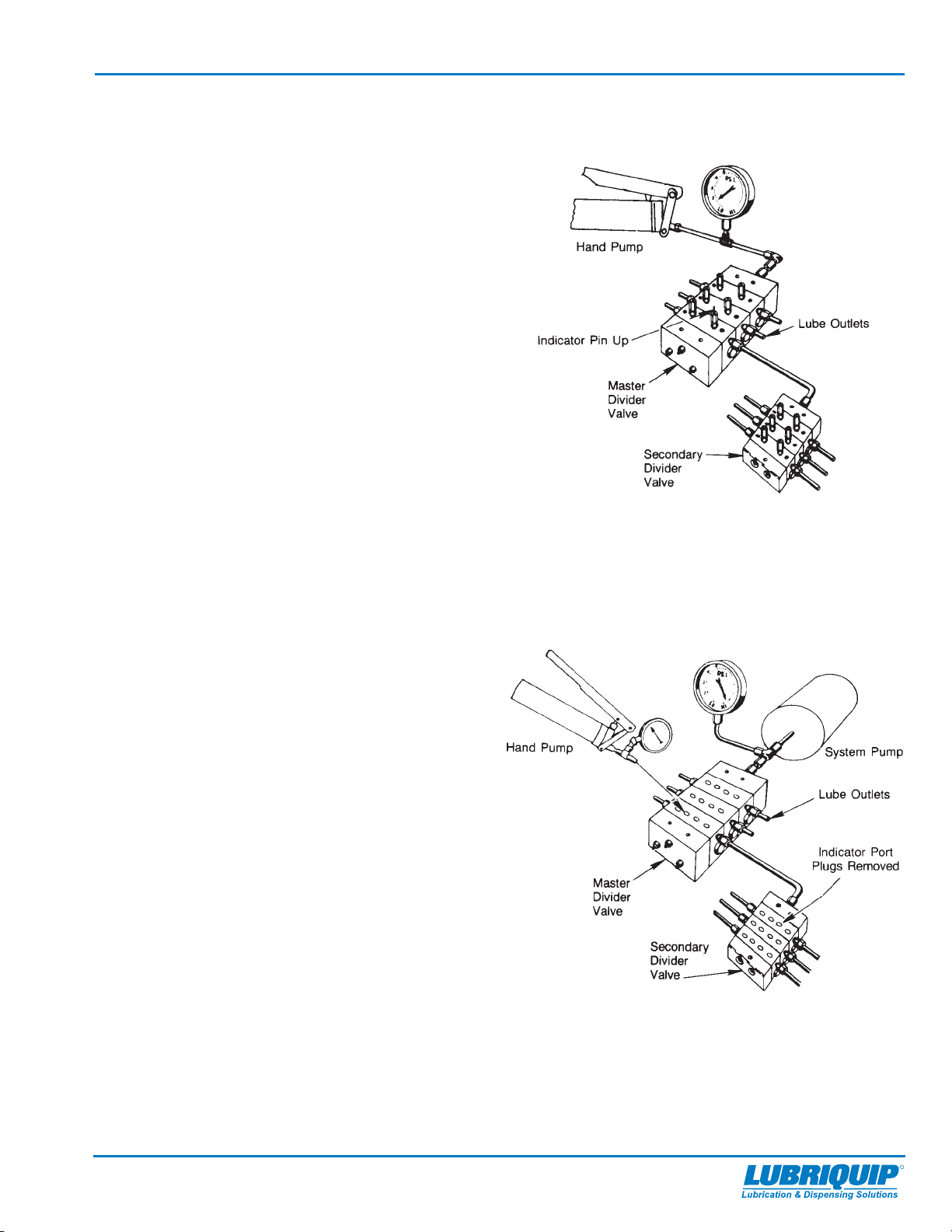
2-1. Master Divider Valve Equipped With Performance
Indicator:
With manual pump connected to the master divider valve as
outlined in Step 1, raise pressure to 2,000 PSI, the indicators
in the indicator ports will signal the location of the blockage.
An indicator in the up position indicates pressure is in that
outgoing line and signals the blockage is in the area being
served from this outlet, as shown in Figure C. See Step 3.
If no indicator pins are protruding, the blockage is in the
master divider valve.
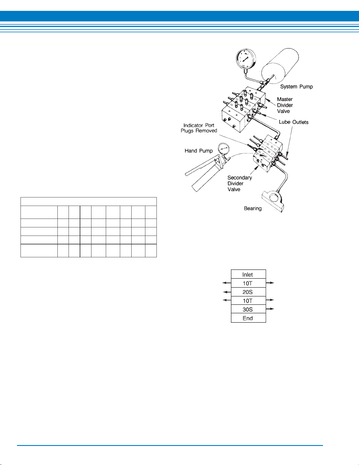
2-2. Master Divider Valve Without Performance
Indicators:
With pressure on the master as outlined in step 2-1, remove
one at a time each indicator port plug and attempt to operate
manual pump after each plug is removed. Do not exceed
2,000 PSI. If pressure drops and master cycles freely after an
indicator port plug is removed then blockage is downstream in
the area that is being served from that outlet. See Step 3.
If all indicator port plugs are removed and master will not
cycle, blockage is in this divider valve.
Note: When indicator port plug of a blocked area is removed
a small shot of trapped lubricant will usually surge out of this
outlet as the inlet pressure on the divider valve drops.
If testing in Step 2 (1 or 2) indicates a blockage in the master
divider valve, this divider valve must be disassembled and
cleaned. See Step 5 for instructions on correct procedure.
Page 3
30101
Locating Blockage in Series-Flo®Systems
R
Step No. 3 —
Testing accomplished in Step 2 has indicated the blockage is
downstream of the master divider valve. Install the manual
pump in the indicator Port of the master divider valve that is
common to this blocked area. See Figure D. Proceed to
downstream secondary divider valve and remove all indicator
port plugs. Slowly operate manual pump. If lubricant can be
discharged freely through each of the indicator ports of this
divider valve the blockage is not in the supply line or the
divider valve, see Step 4. If lubricant is not freely discharged
through the open indicator ports of the secondary divider
valve the blockage is in this divider valve or its supply line.
Disconnect supply line at secondary inlet fitting and slowly
operate manual pump to verify location. If blockage is in
divider valve see Step 5.
Step No. 4 —
Install manual pump into each indicator port of secondary
divider valve in turn, and slowly operate pump. See Figure E.
If high pressure exists blockage has been located. Look for
crushed line, tight bearing, improperly drilled fittings
and/or lube inlet port. Correct as necessary.
Step No. 5 —
When testing indicates a blockage has occurred in any
divider valve, that divider valve must be disassembled and
cleaned.
Note: Dirt and foreign material are the worst
enemies of any lubricating equipment. All servicing
and disassembling should be carried out under the
cleanest possible conditions.
Before disassembling any divider valve make a sketch and
note as to the arrangement of the intermediate sections. For
example: INLET 10T-20S-10T-30S END. See Figure F. Also
remove end plugs only and try to move each piston back and
forth without removing the piston from the intermediate
section.
Caution — -
Do not insert hard metal objects into piston bore (i.e.,
punches, screwdrivers, etc.) use a brass rod and hand
pressure only.
If all pistons are movable and there is no indication of a more
serious problem, replace end plugs and using a new gasket
apply the correct torque, see Torque Table. Retest this
divider valve using the manual pump. If a piston is jammed, or
a hard wax-like substance, or dirt is noted at the end of the
piston chamber, proceed with disassembly. The divider valve
can be dismantled by removing the tie rod nuts. With the
individual sections on the bench remove the end plug from
both ends of the section. Taking one section at a time remove
the piston, if it appears to be jammed, try removing it from the
other direction. With badly jammed pistons it may be neces-
sary to use a brass rod and lightly tap piston out.
Figure D
Figure C
®RegisteredtrademarkofLUBRIQUIP, INC.,
Printed in the USA
LUBRIQUIP, INC., 18901 Cranwood Pkwy., Cleveland, Ohio 44128, 216-581-2000 or 1-800-USA-LUBE, FAX: 216-581-8945
Clean sections and pistons in a suitable clean solvent until
all lubricant has been removed. Use compressed air to dry
and blow out all ports thoroughly. A small wire probe should
be used to make sure all passages are clean and open.
Inspect the cylinder bore and piston carefully for scratches,
score marks or other damage.
Note: If either piston or cylinder bore is damaged a new
section must be installed. All pistons are selectively
fitted to the bore for proper clearance. Care must
be taken to install piston only into the intermediate
section from which it was removed.
If divider valve section and piston both appear in good
condition, reassemble section making certain that piston
slides smoothly but snugly in cylinder bore. Repeat cleaning
and inspection of each section. After all sections have been
cleaned, blown out, inspected and found to be in good
condition, reassemble divider valve as indicated by the
notes and sketches.
Caution — -
Use all new gaskets, and correct torque ratings listed below.
Test operation of divider valve using manual pump.
CONTAMINATION BLOCKAGE
If dirt, foreign material or any other form of contamination is
found in a divider valve, cleaning that divider valve will only
temporarily solve contamination blockage problems. The
source of the contamination must be eliminated for
satisfactory service. The system filtering method must be
investigated, filter elements should be inspected or changed
as required. The reservoir must be inspected and cleaned if
necessary. The reservoir filling method should be reviewed
to eliminate any chance of foreign material entering the
reservoir during filling. All lubricating systems require filtered
lubricant.
SEPARATION BLOCKAGE
If a hard wax or soap like material is found in the intermedi-
ate section grease separation is occurring. This means that
the oil is being squeezed from the grease at normal system
operating pressure and the grease thickener is being
deposited in the divider valve. Cleaning the divider valve will
usually result in only temporarily solving the problem.
Consult your lubricant supplier for recommendations on
alternate lubricants and your local Trabon Distributor to
verify compatibility with centralized lubricating Systems.
)sbL.tF(euqroTylbmessA
JMM VMHVM
/PSM
HMXMPXMGM
stuNdoReiT21020242832921
sgulProtacidnI751515101815181
sgulPdnE5151515111535351
noitceSevla
V
wercSgnitnuoM   9 31
Figure F
Figure E
ISO 9000:2000
REGISTERED FIRM
ISO 14001
REGISTERED FIRM
Bulletin 30101
Trabon®and Manzel®Locating Blockage in Series-Flo®Systems

This manual suits for next models

1

Popular Lubrication System manuals by other brands

Nordson MicroCoat MC800 Series operating manual

Nordson

Nordson MicroCoat MC800 Series operating manual

GUDEL FlexxPump 402 operating manual

GUDEL

GUDEL FlexxPump 402 operating manual

Lincoln Quicklub 203 Series owner's manual

Lincoln

Lincoln Quicklub 203 Series owner's manual

MATO centraFILL standard operating instructions

MATO

MATO centraFILL standard operating instructions

Perma FUTURA Operator's guide

Perma

Perma FUTURA Operator's guide

SKF HS04 Assembly instructions

SKF

SKF HS04 Assembly instructions

Perma CLASSIC Series operating instructions

Perma

Perma CLASSIC Series operating instructions

Norgren L74M Installation & maintenance instructions

Norgren

Norgren L74M Installation & maintenance instructions

Atlas Copco BLG 10 Operator instructions

Atlas Copco

Atlas Copco BLG 10 Operator instructions

Lincoln 3675 user manual

Lincoln

Lincoln 3675 user manual

BEKA FKGGM-EP V DC Original Operating and Assembly Instructions

BEKA

BEKA FKGGM-EP V DC Original Operating and Assembly Instructions

simalube multipoint 5x8 user manual

simalube

simalube multipoint 5x8 user manual

Perma NOVA 125 operating instructions

Perma

Perma NOVA 125 operating instructions

IMI norgren Micro-Fog L68C Installation & maintenance instructions

IMI

IMI norgren Micro-Fog L68C Installation & maintenance instructions

GUDEL 404DLS operating manual

GUDEL

GUDEL 404DLS operating manual

Bijur Delimon WS-E operating manual

Bijur Delimon

Bijur Delimon WS-E operating manual

Groeneveld OnePlus General manual

Groeneveld

Groeneveld OnePlus General manual

manuals.online logo
manuals.online logoBrands
  • About & Mission
  • Contact us
  • Privacy Policy
  • Terms and Conditions

Copyright 2025 Manuals.Online. All Rights Reserved.