THERMASTRIP Installation Instructions
4 | P a g e
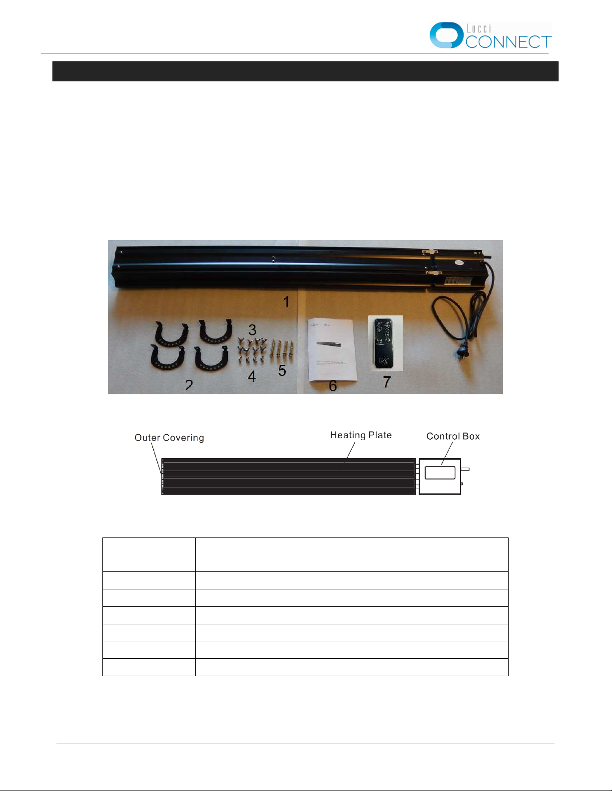
INSTALLATION REQUIREMENT
•The heaters are with plug (1800 & 2300W) and hardwired (3000W) version. Fixed wirings MUST BE
installed by a licensed electrician.
•All wiring and installation of the appliance must adhere to the local council regulation and the latest local
and national wiring rules, eg. AS/NZS 3000 electrical installations.
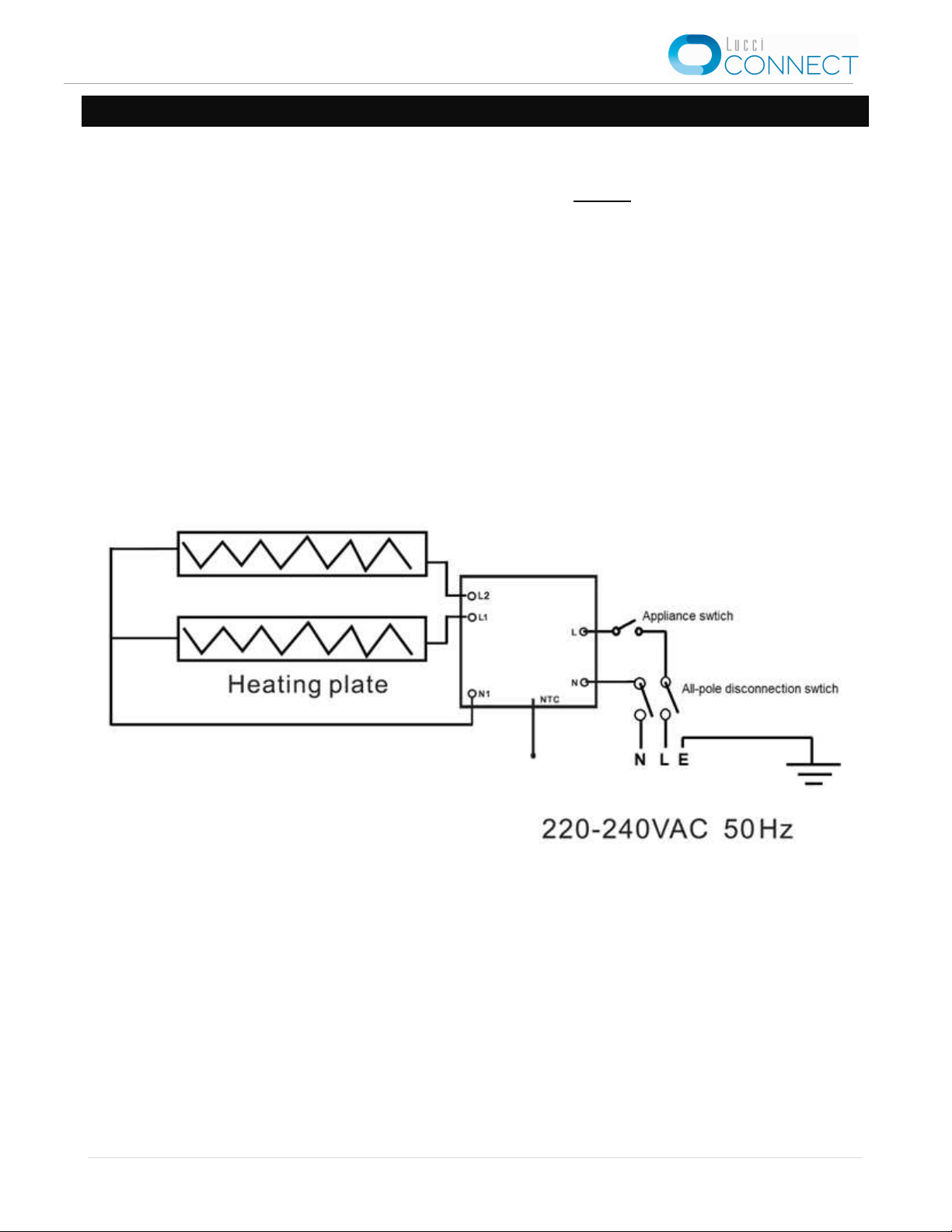
•Before installing SKU#209070 / 209071, check the installation location in the ceiling/wall has access to a
socket outlet that is connected to a wall switch. If it does not, please contact a licensed electrician to
arrange the installation of the socket outlet and wall switch before continuing. Refer to the circuit diagram
section for more information.
•WARNING: Fire risk exists if the heater is covered by or positioned close to curtains or other
combustible materials.
•WARNING: This heater is not equipped with a device to control the room temperature. Do not use
this heater in small rooms when they are occupied by persons not capable of leaving the room on
their own.
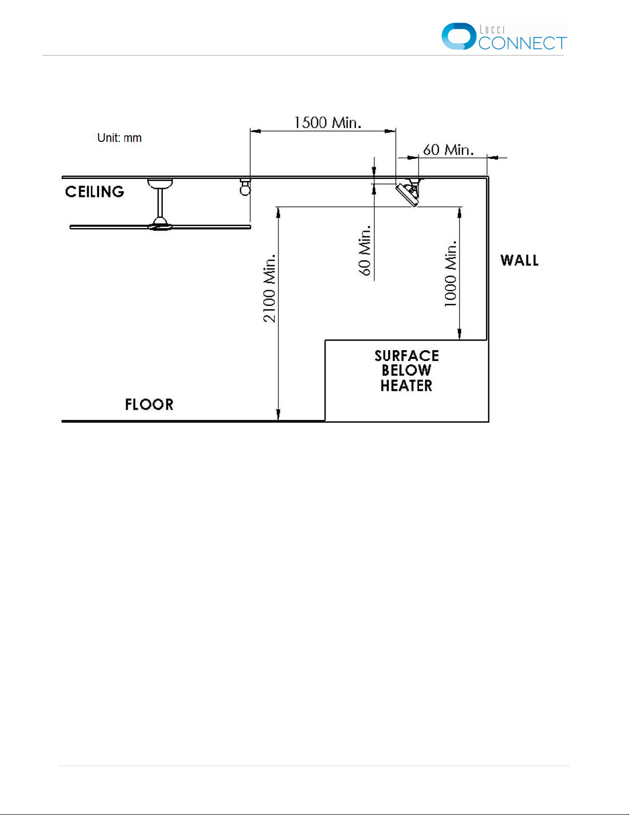
•This product must be installed at least 2.2 m above the floor level. (Refer to figure 2.3)
•This product is rated IP42 and it is suitable for the indoor and alfresco area. When installed in the
alfresco area, it MUST BE installed fully undercover.
•The mounting point must be able to support at least 4 times the weight of the heater.
•Ensure all the clearance values to the structural building element are maintained according to the
clearance diagram. (Refer to figure 2)
•Ensure the heater is kept at a safe distance from other furniture or appliances to avoid a hazard.
•Do not place the product close to a radiant heat source.
•Do not use in areas where gasoline, paint or other flammable liquids are used or stored.
•Do not immerse the heater in liquid or allow liquid to enter the interior of the heater, as this could cause
an electric shock.
•The heater must not be located immediately below a socket-outlet. (Refer to figure 3)
•Seek assistance from a qualified electrician for any mechanical adjustments, service or repairs.
•Do not touch the appliance with wet hands.
•Do not connect the appliance to the mains voltage until it is fully installed in the desired position.
•Do not use the appliance in the immediate surroundings of a bath/shower, swimming pool or any liquid
container.
•Do not allow any cables, furnishings, flammable materials or other items to come in contact with any
surface of the heater.
•If installed in wet areas, the heater switches or controls must be located so that they cannot be touched
by persons in the bath or shower.
•WARNING: To prevent strangulation and shock hazard to children, the flexible wiring connected to
this appliance shall be effectively fixed to the wall.