manuals.online logo
Brands
  1. Home
  2. •
  3. Brands
  4. •
  5. Lumberjack
  6. •
  7. Power Tools
  8. •
  9. Lumberjack BJ1100 Installation manual

Lumberjack BJ1100 Installation manual

Other Lumberjack Power Tools manuals

Lumberjack CBS45LS User manual

Lumberjack

Lumberjack CBS45LS User manual

Lumberjack DP16-1050B User manual

Lumberjack

Lumberjack DP16-1050B User manual

Lumberjack XP Series Operation instructions

Lumberjack

Lumberjack XP Series Operation instructions

Lumberjack HG1800 Installation manual

Lumberjack

Lumberjack HG1800 Installation manual

Lumberjack BM16 User manual

Lumberjack

Lumberjack BM16 User manual

Lumberjack PR12 User manual

Lumberjack

Lumberjack PR12 User manual

Lumberjack ST2000-15 User manual

Lumberjack

Lumberjack ST2000-15 User manual

Lumberjack TTA-MULTI User manual

Lumberjack

Lumberjack TTA-MULTI User manual

Lumberjack DP20-1630F Installation manual

Lumberjack

Lumberjack DP20-1630F Installation manual

Lumberjack HG2000 Installation manual

Lumberjack

Lumberjack HG2000 Installation manual

Lumberjack MT250 Installation manual

Lumberjack

Lumberjack MT250 Installation manual

Lumberjack HG2000P Installation manual

Lumberjack

Lumberjack HG2000P Installation manual

Lumberjack DRT170/120 Installation manual

Lumberjack

Lumberjack DRT170/120 Installation manual

Lumberjack XP Series Operation instructions

Lumberjack

Lumberjack XP Series Operation instructions

Lumberjack VSJ100 Installation manual

Lumberjack

Lumberjack VSJ100 Installation manual

Lumberjack DP13-580B Installation manual

Lumberjack

Lumberjack DP13-580B Installation manual

Popular Power Tools manuals by other brands

ISLAND HOPPER Power Egg HT-309 operating instructions

ISLAND HOPPER

ISLAND HOPPER Power Egg HT-309 operating instructions

Sioux Tools SSR6P25 Instructions-parts list

Sioux Tools

Sioux Tools SSR6P25 Instructions-parts list

Makita HM1317C technical information

Makita

Makita HM1317C technical information

ABB Smart Tool + quick start guide

ABB

ABB Smart Tool + quick start guide

Baumr-AG BMJK-24S user manual

Baumr-AG

Baumr-AG BMJK-24S user manual

Bosch Professional GST 18 V-LI S Original instructions

Bosch

Bosch Professional GST 18 V-LI S Original instructions

Ronix RA-2702 quick start guide

Ronix

Ronix RA-2702 quick start guide

Nordson ProBlue user guide

Nordson

Nordson ProBlue user guide

aoyue int6028 instruction manual

aoyue

aoyue int6028 instruction manual

Hitachi CJ 65VA2 Instruction manual and safety instructions

Hitachi

Hitachi CJ 65VA2 Instruction manual and safety instructions

Makita HM1304 instruction manual

Makita

Makita HM1304 instruction manual

Kurtz Ersa Ersa X-TOOL VARIO operating instructions

Kurtz Ersa

Kurtz Ersa Ersa X-TOOL VARIO operating instructions

SCHUNK KSO 65 Installation and operating instruction

SCHUNK

SCHUNK KSO 65 Installation and operating instruction

Harken LokHead 500 user manual

Harken

Harken LokHead 500 user manual

Senco DuraSpin ExTPro installation instructions

Senco

Senco DuraSpin ExTPro installation instructions

Ferm JSM1020 Original instructions

Ferm

Ferm JSM1020 Original instructions

Milwaukee M12 FUEL 2559-20 Operator's manual

Milwaukee

Milwaukee M12 FUEL 2559-20 Operator's manual

EINHELL BT-CD 12/2 operating instructions

EINHELL

EINHELL BT-CD 12/2 operating instructions

manuals.online logo
manuals.online logoBrands
  • About & Mission
  • Contact us
  • Privacy Policy
  • Terms and Conditions

Copyright 2025 Manuals.Online. All Rights Reserved.

BJ1100
ORIGINAL INSTRUCTIONS
SAFETY AND OPERATING MANUAL
6" Bench Top Jointer
BJ1100
2
PRODUCT SPECIFICATIONS
SAFETY INSTRUCTIONS
WARNING: When using electric tools, basic safety precautions should always be followed to reduce the
risk of fire, electric shock and personal injury.
Read all these instructions before operating this machine.
GENERAL
1. Read andunderstand manual.
For your own safety,read and understand the entire instruction manual before operating the Jointer.
2. Read andunderstand warning label.
Read and understand the warning labels posted on the machine.
Failure to comply with all of these labels may cause serious injury.
3. Keep work area clean.
Cluttered areas and benches invite injuries.
4. Consider work area environment.
Do not use power tools in damp or wet locations. Keep work area well lit.
Do not use power tools where there is risk to cause fire or explosion.
5. Guard against electric shock.
Avoid body contact with earthed or grounded surfaces (e.g. pipes, radiators, ranges, refrigerators).
6. Keep children away.
All children should be kept away from the machine when in use.
7. Tool Storage.
When not in use, tools should be stored in a dry, out of reach of children.
8. Do not force the tool.
It will do the job better and safer at the rate for which it was intended.
Jointer / Planer
Motor Power 1100W
Max Cutting Width 153mm ( 6in )
Max Cutting Depth 3mm ( 1/8in )
Cutterhead Rotation Speed 10000 RPM
Number of Blades 2 Blades
Table Size 725 X 160mm ( 28-1/2 X 6-1/4 in )
Fence Size 530X110mm ( 21 X 4-1/4 in )
Dust Collection Port 60.5mm ( 2-1/2 in )
Fence Angle 0 to 45°
3
9. Dress properly.
Do not wear loose clothing or jewelery, they can be caught in moving parts. Wear protective hair covering to
contain long hair.
10. Use safety glasses and hearing protection.
Also use face or dustmask ifthe cutting operation is dusty.
11. Disconnect tools.
When not in use, before servicing and changing accessories such as blades, make sure the tool is
disconnected from the power supply.
ADDITIONAL SAFETY RULES FOR THIS PRODUCT
1. Be alert and think clearly.Never operate power tools when tired, intoxicated or when taking medications that
cause drowsiness.
2. Keep hands away from moving parts and cutting surfaces.
3. Handle workpiece correctly.Protect hands from possible injury.
4. Do not perform jointing/planing operations on material shorter than 200mm ( 8″), or less than
6mm(1/4″) thick.
5. Never make jointing cut deeper than 1/8″.
6. Do not back the work towardsthe in-feed table.
7. Support the workpiece adequately at alltimes during operation.
8. Use push block/push stick for jointing material narrower than 75mm (3″) or planing material thinner than
75mm ( 3″).
9. Take precautions against kickback. Do not permit anyone to stand or cross in line of cutterhead’s rotation.
10. Replace or sharpen blades as they become damaged or dull.
ACCESSORIES AND ATTACHMENTS
RECOMMENDED ACCESSORIES
WARNING: To avoid injury:
Use only accessories recommended for this machine.
Follow instructions that accompany accessories. Use of improper accessories may cause
hazards.
Use only accessories designed for this machine to avoid injury from thrown broken parts or
work pieces.
Do not use any accessory unless you have completely read the instruction or operator’s
manual for that accessory.
4
CARTON CONTENTS
UNPACKING AND CHECKING CONTENTS
Carefully unpack the machine and all its parts, and compare against the illustration following.
WARNING:
To avoid injury from unexpected starting, do not plug the power cord into a power source receptacle during
unpacking and assembly.
This cord must remain unplugged whenever you are assembling or adjusting the machine.
If any part is missing or damaged, do not plug the machine in until the missing or damaged part is replaced,
and assembly iscomplete.
TABLE OF LOOSE PARTS
Unpack carton; check you machine to see parts listed below:
1. Jointer
2. 8mm Flat washer
3. Knob
4. Fence
5. Fence support assembly
6. Fence sliding base
7. Bridge cover assembly
8. Spring
9. 4mm Hex wrench
10. Lock handle
11. Flat washer
12. Square nut
13. Filter bag
14. Dust chute
15. Push block
16. Push stick
1
3
5 6
9
10
12
13 14
8
11
15
16
2
7
4
5
ASSEMBLY
THE FENCE
Align the T-slot on the fence to the nut
on fence support assembly,slide the
fence onto the nut until the arc groove
aligns the Fence support
center. Tighten the four flat head
screws to fix the fence.
Remove the two socket pan head
screwsfromthe jointer. Attach the
fence sliding base to the jointer, fix it
by using the two socket pan head
screws
Fix the fence and fence support onto
the sliding base by using the lock
handle, flat washer and square nut.
Fence
Nut
Arc groove
Flat head screw
Socket pan head screws
Fence sliding base
Square nut
Lock handle
6
CHECK AND ADJUST THE FENCE ANGLE
Before adjusting the fence, makesure thepower isturn off.
Using a combination square, check the 0º angle. If necessary adjust the 0º stop and set angle pointer at
0º.
Using the combination square, check the 45ºangle between the fence and table. If necessary, adjust the
45ºstop .
ATTENTION: The lowest line of the fence should always sit onthe out-feed table.
INSTALL THE BRIDGE COVER ASSEMBLY
Attach the bridge cover assembly to the jointer with the knob and flat washer.
Combination square
0ºstop
Angle pointer
Combination square
45ºstop
Knob
Flat washer Bridge cover
7
INSTALL THE DUST CHUTE AND FILTER BAG
Slide dust chute onto end of chip port.Tighten the pan head screw.
Open the zipper on the bottom of the bag, place the spring inside of the filter bag arm.
Slide the arm with the spring over the dust chute.
Close the zipper.
Mounting jointer to bench table
Foreffective and safe operation, the jointer should be mounted to a bench table.
Use the four mounting holes on the base to fix the jointer to a bench table.
Spring
Filter bag
Dust chute
8
OPERATION INSTRUCTIONS
Jointing is asurfacing operation in which asmall amount of wood is removed from the edges and faces
of boards to get smooth, straight andevensurfaces such that the two edges that run across the
planning blocks would fit together perfectly, forming a seamless joint.
Planing refers to the sizing of lumber to a desired thickness while creating a level surface parallel to the
opposite size of the board. Depth of cutis the term used toindicate how deep the blades will cutinto the
workpiece.
ADJUSTING THE DEPTH OFCUT
The depth of cut isadjusted by the relative positioning of the in-feed table with respect to the
cutterhead. In-feed table can be raised or lowered using the hand wheel.
Turning the hand wheel anticlockwise will lower the in-feed table causing more wood to be removed
from workpiece.
Turning the hand wheel clockwise will raise the in-feed table causing less wood to be removed
from workpiece.
Do not make jointing or planing cuts deeper than 1/8″.
ADJUST THE FENCE POSITION
Before adjusting the fence, make sure the power is turned off.
Loosen the fence tilting handle. Adjust the fence to desired angle and re-tighten the handle.
Loosen the fence sliding handle. Slide the fence to desired position and re-tighten the
handle. ATTENTION: The lowest line of the fence should always sitonthe out-feed table.
In-feed table
Hand wheel
Cutting depth display
Fence tilting handle
Fence sliding handle
9
ADJUSTING BLADE HEIGHT
CAUTION: Make sure the machine is unplugged before proceeding with checking blades.
The blades have been adjusted at the factory to assure proper operation and should require no adjustment.
However, shipping and handling may have caused misalignment. For accurate cutting, the blades must be
as high as the out feed table when positioned at the highest point.
To check blade height:
Loosen the bridge cover locking knob, pull out the bridge cover.
Turn the cutter head so that one of the blades is at the highest position.
CAUTION: The cutter head blades are extremely sharp. Do not let your fingers contact the cutting edge at
any time.
Place a straightedge over the out feed table and the blade
The straight edge must touch evenly on the out feed table at both ends of the blade.
Rotate the cutter head by hand. The blades should just touch the straightedge. Ifa blade is too low or too
high at either end, adjust blade height using the jack screws.
AVOID DAMAGE TO BLADES
This Planer is a precision woodworking machine and should only be used on quality lumber. Using bad lumber
could result in a poor quality cut on subsequent pieces.
For proper operation, it is preferable to use the Planer with adust collecting system attached to the chip port in
the rear of the jointer. Attaching a dust collecting system isespecially required when taking deeper cuts to
prevent clogging of wood chips
Do not use dirty boards. Dirt and stones are abrasive and will wear the blade quickly.
Remove nails and staples from the wood before planing.
Avoid knots. Heavy cross-grain makes knots hardand they can come loose and jam the planer.
Assess value of badly warped boards. Operator can be tempted to use too deep of cut to square boards
quickly.Use several passes to maintain a level surface so you do not wear or jam the blades.
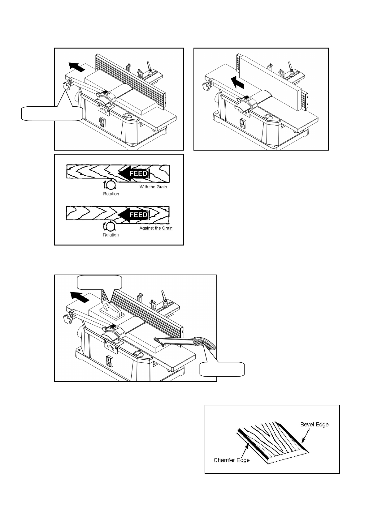
FEEDING WORKPIECE
Feed rate refers to the rate at which wood is passed over the blades, an even feed will produce a uniformed job.
To feed work piece:
Adjust the bridge cover to desired position, and tighten the knob.
Hold the work piece firmly down on the feed table and against the fence.
Feed the work piece at an even rate over the cutterhead, any hesitation or stopping will cause a “step” to be
cut in the work piece.
Asyour trailing hand passes over the cutter head remove your leading hand and place behind your trailing hand
and repeat until the entire length of work piece has been cut.
Lock knob
Bridge cover
10
Feed with the grain whenever possible, if the nature of the work piece is such that it must be fed against the
grain take very light cuts and feed slowly. When using long work pieces use extra supports at both end of the
planer.
For your safety,use the push block and push stick to hold and feed the workpiece when jointing wood
that isnarrower than 75mm (3″), planing wood thinner than 75mm (3″).
BEVELING AND CHAMFERING
The fence on the jointer/planer isadjustable from 0° to
45°. Adjust the fence to the desired angle and tighten
the fence tilting handle.
Beveling refers to cutting the entire edge of a board at
an angle. Beveling may require several passes due to
the depth of cut needed.
Chamfering refers to removing only the corner of the
edge of a board. Normally a chamfer ismade on one
pass.
Push stick
Push block
Tighten the knob