lumen8 Kudos 150 User manual

Kudos 150
Order code: ELUM034
User Manual
www.prolight.co.uk
1A
CONTENTS
1. Safety Instructions ........................................................................................2
2. Technical Specifications ...............................................................................5
3. How To Set The fixture .................................................................................5
3.1 Control panel .........................................................................................5
3.2 Main Function........................................................................................6
3.3 Home Position Adjustment ..................................................................13
4. How To Control The fixture .........................................................................14
4.1 Master/Slave........................................................................................14
4.2 Easy Controller ....................................................................................15
4.3 DMX Controller ....................................................................................15
4.4 DMX 512 Configuration .......................................................................16
4.5 DMX512 Connection ...........................................................................22
5. Troubleshooting ..........................................................................................23
6. Fixture Cleaning..........................................................................................25

2A
1. Safety Instruction
WARNING
!Please keep this User Guide for future consultation. If you sell the unit to another user, be
sure that they also receive this instruction booklet.
!Unpack and check carefully there is no transportation damage before using the unit.
!Before operating, ensure that the voltage and frequency of power supply match the power
requirements of the unit.
!It’s important to ground the yellow/green conductor to earth in order to avoid electric
shock.
!The unit is for indoor use only. Use only in a dry location.
!The unit must be installed in a location with adequate ventilation, at least 50cm from
adjacent surfaces. Be sure that no ventilation slots are blocked.
!Disconnect main power before replacement or servicing.
!Make sure there are no flammable materials close to the unit while operating as it could
present a fire hazard.
!Use safety cable when fixes this unit. DO NOT handle the unit by taking its head only, but
always by taking its base.
!Maximum ambient temperature is Ta: 40 degrees. DO NOT operate it where the
temperature is higher than this.
!Unit surface temperature may reach up to 85 degrees. DO NOT touch the housing
bare-hand during its operation. Turn off the power and allow about 15 minutes for the unit
Please read carefully these instructions, which includes important
information about the installation, usage and maintenance.
3A
to cool down before replacing or serving.
!In the event of serious operating problem, stop using the unit immediately. Never try to
repair the unit by yourself. Repairs carried out by unskilled people can lead to damage or
malfunction. Please contact the nearest authorised technical assistance center. Always
use the same type spare parts.
!DO NOT touch any wire during operation as high voltage might be causing electric shock.
Warning:
!To prevent or reduce the risk of electrical shock or fire, do not expose the unit to rain or
moisture.
!DO NOT open the unit within five minutes after switching off.
!The housing, the lenses, or the ultraviolet filter must be replaced if they are visibly
damaged.
!Do not stare directly into the light
!Do not operate the fixture near stairways
!Provide advance notice that strobe lighting is in use
!Avoid extended periods of continuous flashing, particularly at frequencies of 10 to 20
flashes per second
Caution:
There are no user serviceable parts inside the unit. Do not open the housing or
attempt any repairs yourself. In the unlikely event your unit may require service,
please contact your nearest dealer.

4A
Installation:
The unit should be mounted via omega bracket (see below). Always ensure that the unit is
firmly fixed to avoid vibration and slipping while operating. And make sure that the
structure to which you are attaching the unit is secure and is able to support a weight of 10
times of the unit’s weight. Also always use a safety cable that can hold 12 times of the
weight of the unit when installing the fixture.
The equipment must be fixed by the professionals. And it must be fixed at a place where
is out of the touch of people and has no one pass by or under it.
5A
2. Technical Specification
◇Extremely small, fast and powerful LED moving beam and wash effect.
◇DMX Channels: 1/9/12/14/16/28 channel mode
◇Beam angle: 10 degrees
◇Smooth electronic dimming: 0-100%
◇Electronic strobe with pulse and random effects
◇Optional easy controller CA-8 or CA-9 RTX for instant lighting shows at your fingertips
◇High efficiency, low power consumption
◇Super compact, low weight
Power Supply:AC 100V~240V, 50/60Hz
Fuse: T 6.3A
Power consumption: 105W
Light source: 7 x 10W RGBW Cree LED
Weight: 5.7Kgs
Dimension: 258 x 167 x 322mm
3. How To Set The Unit
3.1 Control panel

6A
Display:
To show the various menus and the selected functions
LED:
DMX
On
DMX input present
MASTER
On
Master Mode
SLAVE
On
Slave Mode
SOUND
Flashing
Sound activation
Button:
MENU
To select the programming functions
DOWN
To go backward in the selected functions
UP
To go forward in the selected functions
ENTER
To confirm the selected functions
Only for remote control:
Connecting with CA-8/ CA-9RTX to control the unit for Stand by, Function and
Mode function.
Mains input:
Connect to power supply.
Mains output:
Connect to supply power to the next unit.
DMX input/output:
For DMX512 link, use 3/5-pin XLR cable to link the unit together.
3.2 Main Function
To select any of the given functions, press the MENU button up to when the required one is
showing on the display. Select the function by ENTER button and the display will blink. Use
DOWN and UP button to change the mode. Once the required mode has been selected,
press the ENTER button to setup, to go back to the functions without any change press the
7A
MENU button again.Hold and press the MENU button about one second or wait for one
minute to exit the menu mode.
The main functions are showing below:

8A
9A
DMX Address
Select DMX Address, press the ENTER button to confirm, the present address will blink on
the display. Use the UP and DOWN button to adjust the address from 1to 512. Once the
address has been selected, press the ENTER button to setup, to go back to the functions
without any change press the MENU button again.Hold and press the MENU button about
one second or wait for one minute to exit the menu mode.
Channel Mode
Select Channel Mode, press the ENTER button to confirm, present mode will blink on the
display. Use the DOWN and UP button to select the 1chan, 9chan, 12chan, 14chan,
16chan or 28chan Mode. Once the mode has been selected, press the ENTER button to
setup, to go back to the functions without any change press the MENU button again.Hold
and press the MENU button about one second or wait for one minute to exit the menu mode.
Show Mode
Select Show Mode, press the ENTER button to confirm, present mode will blink on the
display. Use the DOWN and UP button to select the Show 1 or Show 2 or Show 3 or Show
4Mode. Once the mode has been selected, press the ENTER button to setup, to go back to
the functions without any change press the MENU button again.Hold and press the MENU
button about one second or wait for one minute to exit the menu mode.
Dimmer curve
Select Dimmer curve, press the ENTER button to confirm, present mode will blink on the
display. Use the DOWN and UP button to select the Mode1 or Mode 2 or Mode 3 or Mode
4mode. Once the mode has been selected, press the ENTER button to setup, to go back to
the functions without any change press the MENU button again.Hold and press the MENU
button about one second or wait for one minute to exit the menu mode.

10A
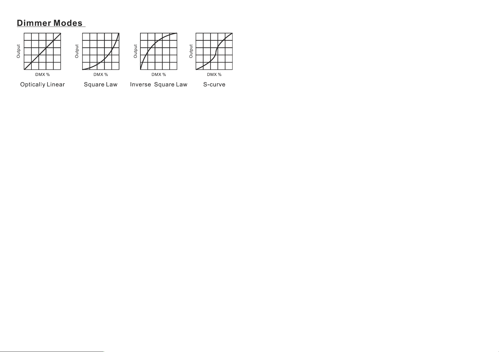
Mode 1 (Optically Linear): The increase in light intensity appears to be linear as
DMX value is increased.
Mode 2 (Square Law): Ligt intensity control is finer at low levels and coarser at
high levels.
Mode 3 (Inverse Square Law): Light intensity control is coarser at low levels and
finger at high levels.
Mode 4 (S-cure): Light intensity control is finger at low levels and high levels and
coarser at medium levels.
Slave Mode
Select Slave Mode, press the ENTER button to confirm, present mode will blink on the
display. Use the DOWN and UP button to select the Slave 1 (normal) or Slave 2 (2 light
show) mode. Once the mode has been selected, press the ENTER button to setup, to go
back to the functions without any change press the MENU button again. Hold and press the
MENUbutton about one second or wait for one minute to exit the menu mode.
Black Out
Select Slave Mode, press the ENTER button to confirm, present mode will blink on the
display. Use the DOWN and UP button to select the Yes (yes blackout) or No (no blackout)
mode. Once the mode has been selected, press the ENTER button to setup, to go back to
the functions without any change press the MENU button again.Hold and press the MENU
button about one second or wait for one minute to exit the menu mode.
Sound State
Select Sound State, press the ENTER button to confirm, present mode will blink on the
display. Use the DOWN and UP button to select the On (sound on) or Off (sound off) mode.
11A
Once the mode has been selected, press the ENTER button to setup, to go back to the
functions without any change press the MENU button again. Hold and press the MENU
button about one second or wait for one minute to exit the menu mode.
Sound Sense
Select Sound Sense, press the ENTER button to confirm, present mode will blink on the
display. Use the DOWN and UP button to change the sound sense from 0…100. Once the
mode has been selected, press the ENTER button to setup, to go back to the functions
without any change press the MENU button again. Hold and press the MENU button about
one second or wait for one minute to exit the menu mode.
Pan Inverse
Select Pan Inverse, press the ENTER button to confirm, present mode will blink on the
display. Use the DOWN and UP button to select the Yes (pan inversion) or No (normal)
mode. Once the mode has been selected, press the ENTER button to setup, to go back to
the functions without any change press the MENU button again. Hold and press the MENU
button about one second or wait for one minute to exit the menu mode.
Tilt Inverse
Select Pan Inverse, press the ENTER button to confirm, present mode will blink on the
display. Use the DOWN and UP button to select the Yes (tilt inversion) or No(normal) mode.
Once the mode has been selected, press the ENTER button to setup, to go back to the
functions without any change press the MENU button again.Hold and press the MENU
button about one second or wait for one minute to exit the menu mode.
Back Light
Select Back Light, press the ENTER button to confirm, present mode will blink on the
display. Use the DOWNand UP button to select the On (Led on) or Off (Led off) mode.
Once the mode has been selected, press the ENTER button to setup, to go back to the
functions without any change press the MENU button again.Hold and press the MENU
button about one second or wait for one minute to exit the menu mode.
Function Delay
Select Function Delay,press ENTER button to confirm, present mode will blink on the

12A
display. Use DOWN and UP button to select the No Delay or 1S/2S/3S Delay (Wait for
1/2/3 seconds before these Functions of 9/16/28CH are activated/deactivated)mode. Once
the mode has been selected, press the ENTER button to setup, to go back to the functions
without any change press the MENU button again. Hold and press the MENU button about
one second or wait for one minute to exit the menu mode.
White Balance
Select White Balance, press the ENTER button to confirm, present mode will blink on the
display. Use the DOWN and UP button to select the Red or Green or Blue. Once the mode
has been selected, press the ENTER button to setup, use the DOWN and UP button to
change the value (125~255). Once the mode has been selected, press the ENTER button to
setup, go back to the functions without any change press the MENU button again.Hold and
press the MENU button about one second or wait for one minute to exit the menu mode.
Manual Test
Select Manu Test, press the ENTER button to confirm, present mode will blink on the
display. Use the DOWN and UP button to select the Pan/ Tilt/ Red1/ Green1/ Blue1/
White1/…Red4/ Green4/ Blue4/ White4/ Dimmer or Strobe. Once the mode has been
selected, press the ENTER button to setup, use the DOWN and UP button to change the
value (0~255). Once the mode has been selected, press the ENTER button to setup, go
back to the functions without any change press the MENU button again.Hold and press the
MENU button about one second or wait for one minute to exit the menu mode.
Auto-Test
Press the MENU button up to when the Auto-Test is blinking on the display. Pressing
ENTER button and the unit will run self-test by built-in program. To go back to the functions
press the MENU button again. Hold and press the MENU button about one second or wait
for one minute to exit the menu mode.
Temperature
Press the MENU button up to when the Temperature Test is blinking on the display.
Pressing ENTER button and the display will show the temperature of the unit. To go back to
the functions press the MENU button again. Hold and press the MENU button about one
second or wait for one minute to exit the menu mode.
13A
Fixture Time
Press the MENU button up to when the Fixture Time is blinking on the display. Pressing
ENTER button and the display will show the number of working hours of the unit. To go back
to the functions press the MENU button again. Hold and press the MENU button about one
second or wait for one minute to exit the menu mode.
Firmware Version
Press the MENU button up to when the Firmware version is blinking on the display.
Pressing ENTER button and the display will show the version of software of the unit. To go
back to the functions press the MENU button again. Hold and press the MENU button about
one second or wait for one minute to exit the menu mode.
PRO Defaults
Press the MENU button to show PRO Defaults on the display. Press the ENTER button and
the display will blink. Use the DOWN and UP button to select the Yes (run built-in program
to set the fixture to PRO Defaults settings) or No. Press the ENTER button to setup, to go
back to the functions without any change press the MENU button again.Hold and press the
MENU button about one second or wait for one minute to exit the menu mode.
Reset
Press the MENU button up to when the Reset is blinking on the display. Pressing ENTER
button and all channels of the unit will return to their standard position.
3.3 Home Position Adjustment
In the main functions, hold Enter button for at least 3 seconds into offset mode, use DOWN
and UP button up to chose Pan Offset or Tilt Offset, pressing ENTER button and the
display will blink. Use DOWN and UP button to adjust the home position of the Pan, Tilt,

14A
Once the position has been selected, press the ENTER button to setup, to go back to the
functions without any change press the MENU button again.Hold and press the MENU
button about one second or wait for one minute to exit the menu mode.
4. How To Control The Unit
You can operate the unit in three ways:
1. Master/slave built-in preprogram function
2. Easy controller
3. Universal DMX controller
No need to turn the unit off when you change the DMX address, as new DMX address
setting will be effect at once. Every time you turn the unit on, it will show “KUDOS CM-150”
on the display and move all the motors to their ‘home’ position and you may hear some
noises for about 20 seconds. After that the unit will be ready to receive DMX signal or run
the built in programs.
4.1 Master/Slave Built In Preprogrammed Function
By linking the units in master/slave connection, the first unit will control the other units to
give an automatic, sound activated, synchronized light show. This function is good when
you want an instant show. You have to set the first unit in master mode Show Mode and
select show 1 or show 2 or show 3 or show 4 mode. Its DMX input jack will have nothing
plugged into it, and Its master LED will be constantly on and sound LED will flash to the
music. The other units will have to set in slave mode and select Slave 1 (normal) or Slave 2
(2 light show) mode, Their DMX cables plugged into the DMX input jacks (daisy chain) and
the slave led lights will constantly on.
15A
2-light show
In slave mode, Slave 1 means the unit works normally and Slave 2 means 2-light show. In
order to create a great light show, you can set Slave 2 on the second unit to get contrast
movement to each other, even if you have two units only.
4.2 Easy Controller
The easy remote control is used only in master/slave mode. By connecting
to the 1/4” microphone jack of the first unit, you will find that the remote
controller on the first unit will control all the other units in Stand by, and
Mode selection.
Stand By
Blackout the unit
Function
1. Sync. Strobe
2. Async strobe
3. Sound Strobe
Show
1-4
1. Pan index
2. Tilt index
3. Dimmer
Fade Speed
1. Fast
2. Middle
3. Slow
Mode
Sound
(LED OFF)
Show
(LED Slow Blinking)
Show
(LED Fast Blinking)
LED ON
4.3 DMX Controller
By using a universal DMX controller to control the units, you will need to set DMX address
from 1 to 512 so that the units can receive DMX signal.
Press the MENU button up to when the DMX Address is showing on the display. Pressing
ENTER button and the display will blink. Use DOWN and UP button to change the DMX512
address. Once the address has been selected, press the ENTER button to setup, to go back
to the functions without any change press the MENU button again.Hold and press the
MENU button about one second or wait for one minute to exit the menu mode.

16A
Please refer to the following diagram to address your DMX512 channel for the first 4 units:
Channel mode
Unit 1
Address
Unit 2
Address
Unit 3
Address
Unit 4
Address
9channels
1
10
19
28
12channels
1
13
25
37
14channels
1
15
29
43
16channels
1
17
33
49
28channels
1
29
57
85
4.4 DMX 512 Configuration
1 channel mode:
17A
9 channel mode:
12 channel mode:

18A
14 channel mode:
19A
16 channel mode:

20A
28 channel mode:
21A

22A
4.5 DMX512 Connection
1. If you using a controller with 5 pins DMX output, you need to use a 5 to 3 pin
adapter-cable.
2. At last unit, the DMX cable has to be terminated with a terminator (3-pin, CABL90),
(5-pin, CABL90). Solder a 120 ohm 1/4W resistor between pin 2(DMX-) and pin
3(DMX+) into a 3-pin XLR-plug and plug it in the DMX-output of the last unit.
3. Connect the unit together in a `daisy chain` by XLR plug from the output of the unit to
the input of the next unit. The cable can not branched or split to a `Y` cable. DMX 512 is
a very high-speed signal. Inadequate or damaged cables, soldered joints or corroded
connectors can easily distort the signal and shut down the system.
4. The DMX output and input connectors are pass-through to maintain the DMX circuit,
when one of the units’ power is disconnected.
5. Each lighting unit needs to have an address set to receive the data sent by the
23A
controller. The address number is between 0-511 (usually 0 & 1 are equal to 1).
6. The end of the DMX 512 system should be terminated to reduce signal errors.
7. 3 pin XLR connectors are more popular than 5 pin XLR.
3 pin XLR: Pin 1: GND, Pin 2: Negative signal (-), Pin 3: Positive signal (+)
5 pin XLR: Pin 1: GND, Pin 2: Negative signal (-), Pin 3: Positive signal (+), Pin 4/Pin 5:
Not used.
5. Troubleshooting
Following are a few common problems that may occur during operation. Here are
some suggestions for easy troubleshooting:
A. The unit does not work, no light and the fan does not work
1. Check the connection of power and main fuse.
2. Measure the mains voltage on the main connector.
3. Check the power on LED.
B. Not responding to DMX controller
1. DMX LED should be on. If not, check DMX connectors, cables to see if link properly.
2. If the DMX LED is on and no response to the channel, check the address settings and
DMX polarity.
3. If you have intermittent DMX signal problems, check the pins on connectors or on PCB
of the unit or the previous one.
4. Try to use another DMX controller.
5. Check if the DMX cables run near or run alongside to high voltage cables that may
cause damage or interference to DMX interface circuit.

24A
C. Some units don’t respond to the easy controller
1. You may have a break in the DMX cabling. Check the LED for the response of the
master/ slave mode signal.
2. Wrong DMX address in the unit. Set the proper address.
D. No response to the sound
1. Make sure the unit does not receive DMX signal.
2. Check microphone to see if it is good by tapping the microphone
E. One of the channels is not working well
1. The stepper motor might be damaged or the cable connected to the PCB is broken.
2. The motor’s drive IC on the PCB might be out of condition
25A
6. Fixture Cleaning
The cleaning of internal and external optical lenses and/or mirrors must be carried out
periodically to optimize light output. Cleaning frequency depends on the environment in
which the fixture operates: damp, smoky or particularly dirty surrounding can cause greater
accumulation of dirt on the unit’s optics.
!Clean with soft cloth using normal glass cleaning fluid.
!Always dry the parts carefully.
!Clean the external optics at least every 20 days. Clean the internal optics at least every
30/60 days.

26A
27A
Declaration of Conformity
We declare that our products (lighting equipments) comply with
the following specification and bears CE mark in accordance with
the provision of the Electromagnetic Compatibility (EMC)
Directive 89/336/EEC.
EN55103-1: 2009 ; EN55103-2: 2009; EN62471: 2008;
EN61000-3-2: 2006 + A1:2009 + A2:2009; EN61000-3-3: 2008.
&
Harmonized Standard
EN60598-2-17:1989 + A2:1991; EN60598-1:2008+ A11: 2009
Safety of household and similar electrical appliances
Part 1: General requirements

28A
This manual suits for next models
1
Table of contents
Other lumen8 Lighting Equipment manuals
Popular Lighting Equipment manuals by other brands

Somogyi Elektronic
Somogyi Elektronic home LA 10 Q instruction manual

Francis
Francis L300RC Explorer H.V User instruction & installation manual

YORKVILLE
YORKVILLE LP-LED4 Service manual

Philips
Philips Lightolier Lytespan 23C39T4 Specifications

Kenway
Kenway 59661 Owner's manual & safety instructions

Nemalux
Nemalux RH-20 Series installation guide