determined from its position. Before connecting the foot
pedal, make sure the master electrical power switch is in the
OFF position to avoid unintentional initiation of light output.
After connecting the foot pedal, and with the light guide
output safely directed into an enclosed optical path (e.g.
microscope input collimator or a beam dump), turn the
master power switch ON to begin operation.
The SOLA and SOLA FISH light engines have a safety
interlock for the light guide that prevents light output unless
a liquid light guide is fully inserted into the light guide port.
Before operating the unit, make sure the 3 mm diameter
liquid light guide is properly installed in the light guide port
(Figure 2). The set screw should be loosened using a 2 mm
hex wrench so the light guide slides all the way into the
receptacle without obstruction. Once the light guide is fully
inserted, lightly tighten the set screw to hold it in place and
prevent inadvertent disconnection. Prior to turning light
output on, be sure the distal end of the light guide is safely
directed into an enclosed optical path (e.g. microscope
input collimator or a beam dump). Do not bend the light
guide beyond its specified minimum bending radius
(40 mm or 1.6 inches). Extreme bending of the light guide may cause permanent deformation, resulting in
decreased light transmission. In the event that the light guide is retracted from the output port during operation, light
output will cease immediately. To restart light output: 1) turn the master electrical power switch off, 2) fully insert
and secure the light guide in the output port (Figure 2), 3) turn the master electrical power switch back on, and then
4) activate light output using the front panel light output control button, foot pedal or serial control device (control
pod or computer workstation). Take necessary precautions to protect yourself and others from the high
intensity light when turning on the unit.
3.3 Operation Using Light Engine Control Pod
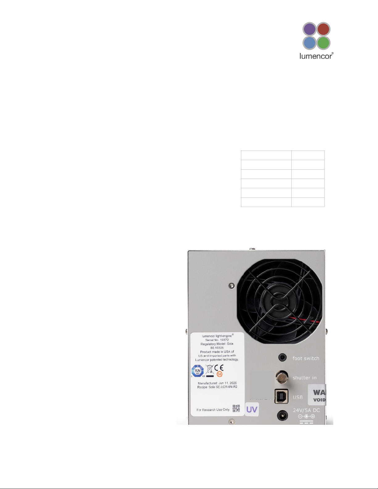
1. Connect the USB A port of the light engine control
pod accessory (Figure 3) to the USB B port on the
SOLA or SOLA FISH (Figure 1) using the USB A-to-
USB B cable (29-10058) [1]. For pass-through
control from a computer workstation, connect the
USB B port of the control pod to a USB A port on
the host computer.
2. The manual light output control button in the top
right corner of the front panel (above the light output
port) should be in the OFF position. This is
necessary to avoid manual override of serial on/off
commands from the pod.
3. Press and hold the right button on the pod until a
menu of light engines appears. Turn the rotary dial to
select “SOLA” from the menu. Press the right button
again to return to the main (0–100 analog intensity) display screen.


 Light Engine User manual")