Safety
Information about chlorine 5
© Lutz-Jesco GmbH 2017
Subject to technical changes.
170518
BA-20710-02-V05
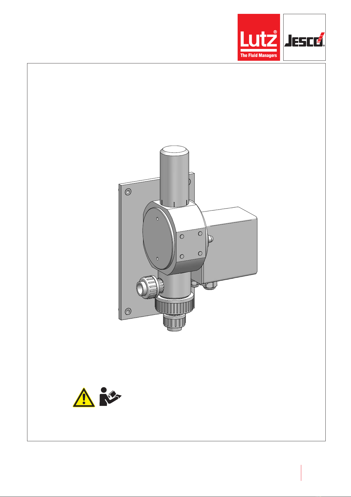
Chlorine control valve C 7700 Operating instructions
2 Safety
2.1 General warnings
The following warnings are intended to help you eliminate the dangers
that can arise while handling the control valve. Risk prevention measures
always apply regardless of any specific action.
Safety instructions warning against risks arising from specific activities
or situations can be found in the respective sub-chapters.
DANGER
Danger to life from chlorine poisoning!
Chlorine is poisonous. In severe cases, breathing in chlorine may lead
to death. It irritates the eyes, the respiratory system and the skin.
ðInstall a gas warning device.
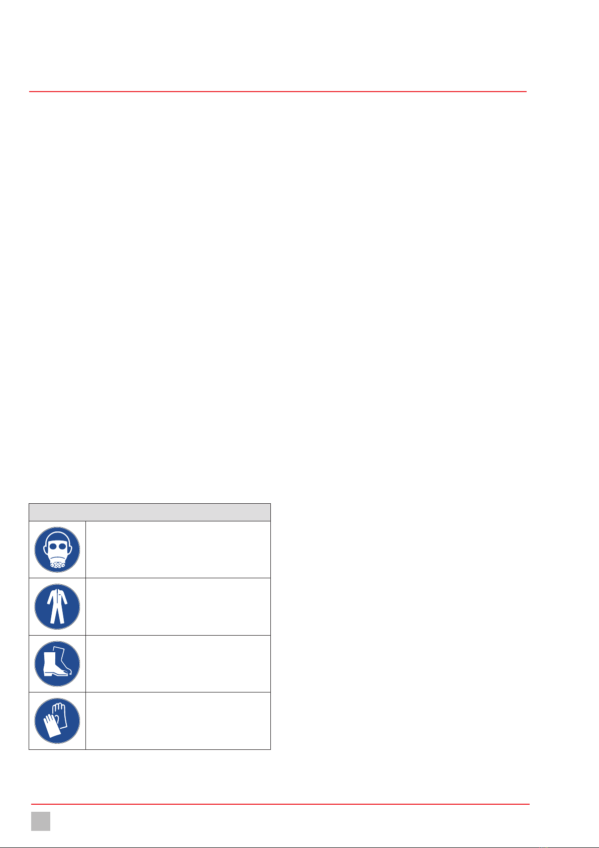
ðUse sufficient personal protective equipment.
ðWhen carrying out any work on the system, use a respirator mask
with a Type B gas filter that complies with EN 14387.
ðAlways comply with the accident prevention regulations that apply
at the place of use.
ðGet rid of leaks without delay. You must get rid of even very minor
leaks without delay. Together with the humidity, chlorine forms
hydrochloric acid and corrosion results in rapidly increasing
leakage.
ðUse only chlorine-resistant seals.
ðOnly use seals once. Reusing them leads to leaks.
DANGER
Increased danger to life from chlorine escape
A fatal quantity of chlorine gas can be released from a leakage.
ðIf chlorine escapes, leave the room immediately.
ðUse sufficient personal protective equipment.
ðIf chlorine gas escapes, wear a Type 2 self-contained breathing
apparatus that complies with EN 137.
ðOnly initiate counter measures after putting on the protective
equipment.
ðGiven a serious escape and insufficient equipment or qualifica-
tions, leave the work to professional emergency services
personnel. Do not take any unnecessary risks.
DANGER
Danger to life through explosions!
When using dosing devices without ATEX certification in a potentially
explosive area, explosions can occur that result in fatal injuries.
ðNever use the device in potentially explosive areas.
WARNING
Increased risk of accidents due to insufficient qualifica-
tion of personnel!
Chlorinators and their accessories must only be installed, operated
and maintained by personnel with sufficient qualifications. Insufficient
qualification will increase the risk of accidents.
ðEnsure that all action is taken only by personnel with sufficient and
corresponding qualifications.
ðPrevent access to the system for unauthorised persons.
NOTE
Damage to the system due to corrosion
Chlorine gas is highly hygroscopic. This means that humidity enters
the system at any open connection on devices or pipes, which results
in the formation of hydrochloric acid and contamination. Thus
inevitably causing damage to the units.
ðKeep all connections (including in the vacuum system and on all
devices not currently in use) closed at all times.
ðAfter maintenance work is complete, remove all water residues
from the system before placing it into operation.
2.2 Information about chlorine
Chlorine is a hazardous substance. The chemical element chlorine is a
greenish-yellow, toxic gas with a pungent odour, which can be detected
in the air at concentrations below 1 ppm (= 1 ml/m³).
Chlorine is 2.5 times heavier than air and accumulates at ground level.
Chlorine is extremely toxic for water organisms. The reason for the
toxicity of chlorine is its extraordinary reactivity. It reacts with animal and
vegetable tissue and thus destroys it.
Air with a chlorine gas content of 0.5 -1% leads to a quick death in
mammals and humans, as it attacks the respiratory tract and the
pulmonary alveolus (formation of hydrogen chloride or hydrochloride
acid).
NOTE
Faults due to insufficient chlorine quality
Impurities in the chlorine gas form deposits in devices and valves and
can attack the components chemically. This can lead to malfunctions.
ðOnly use technically pure chlorine that meets the following
requirements:
- Mass content of chlorine at least 99.5%
- Water content max. 20 mg/kg
Chlorine that complies with EN 937 or EN 15363 meets these
requirements.