Information on this Manual
Validity
This manual is valid for the following devices:SNA3000 WPV/SNA4000 WPV/SNA5000 WPV/SNA6000 WPV
Scope
This manual provides the installation, operation and troubleshooting of this unit, please read this manual
carefully before installations and operations.
Target Group
For qualified persons and end users. Qualified persons and end users must have the following skills:
Knowledge about this unit operation
Training in deal with the security issues associated with installations and electrical safety
Training in the installation and commissioning of electrical devices and installations
Knowledge of the applicable local standards and directives
Safety Instructions
WARNING: This chapter contains important safety and operating instructions. Read and keep this manual
for future reference.
All the operation and connection need to be operated by qualified persons.
Before using the unit, read all instructions and cautionary marking on the unit. Any damage caused by
inappropriate operation is not warranted by Luxpower .
All the electrical installation must comply with the local electrical safety standards.
Do not disassemble the unit. Take it to a qualified service center when service or repair is required,
incorrect re-assembly may result in a risk of electric shock or fire. Do not open inverter cover or change
any components without Luxpower's authorization, otherwise the warranty commitment for the inverter
will be invalid.
To reduce risk of electric shock, disconnect all wirings before attempting any maintenance or cleaning,
turning off the unit will not reduce this risk.
CAUTION-To reduce risk of injury, charge only deep-cycle lead-acid type rechargeable batteries and
lithium batteries, other types of batteries may burst, causing personal injury and damage.
NEVER charge a frozen battery.
For optimum operation of this unit, please follow required spec to select appropriate cable size and breaker.
Please strictly follow installation procedure when you want to disconnect AC or DC terminals, please refer
to INSTALLATION section of this manual for the details.
GROUNDING INSTRUCTIONS -This unit should be connected to a permanent grounded wiring system,
be sure to comply with local requirements and regulation to install this inverter.
NEVER cause AC output and DC input short circuited. Do not connect to the mains when
DC input short circuits.
1. Brief Introduction
1.1 Features of the inverter
SONAR series is a multifunctional, high frequency pure sine wave ECO Hybrid inverter solar inverter, features:
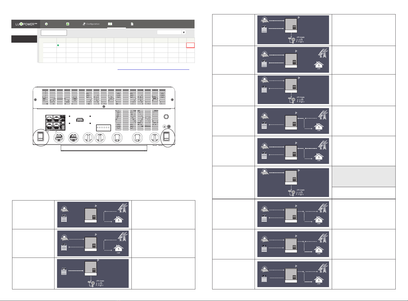
Applicable for pure off grid inverter/ backup power / self-consumption / on grid situation
Integrated with 2 MPPT solar charge controllers, MPPT ranges 120V~385V
Rated power 6KW, power factor 1
Be able to run with or without battery in ongrid and offgrid mode
With separated generator input interface, able to control generator remotely
Solar and utility grid can power loads at the same time
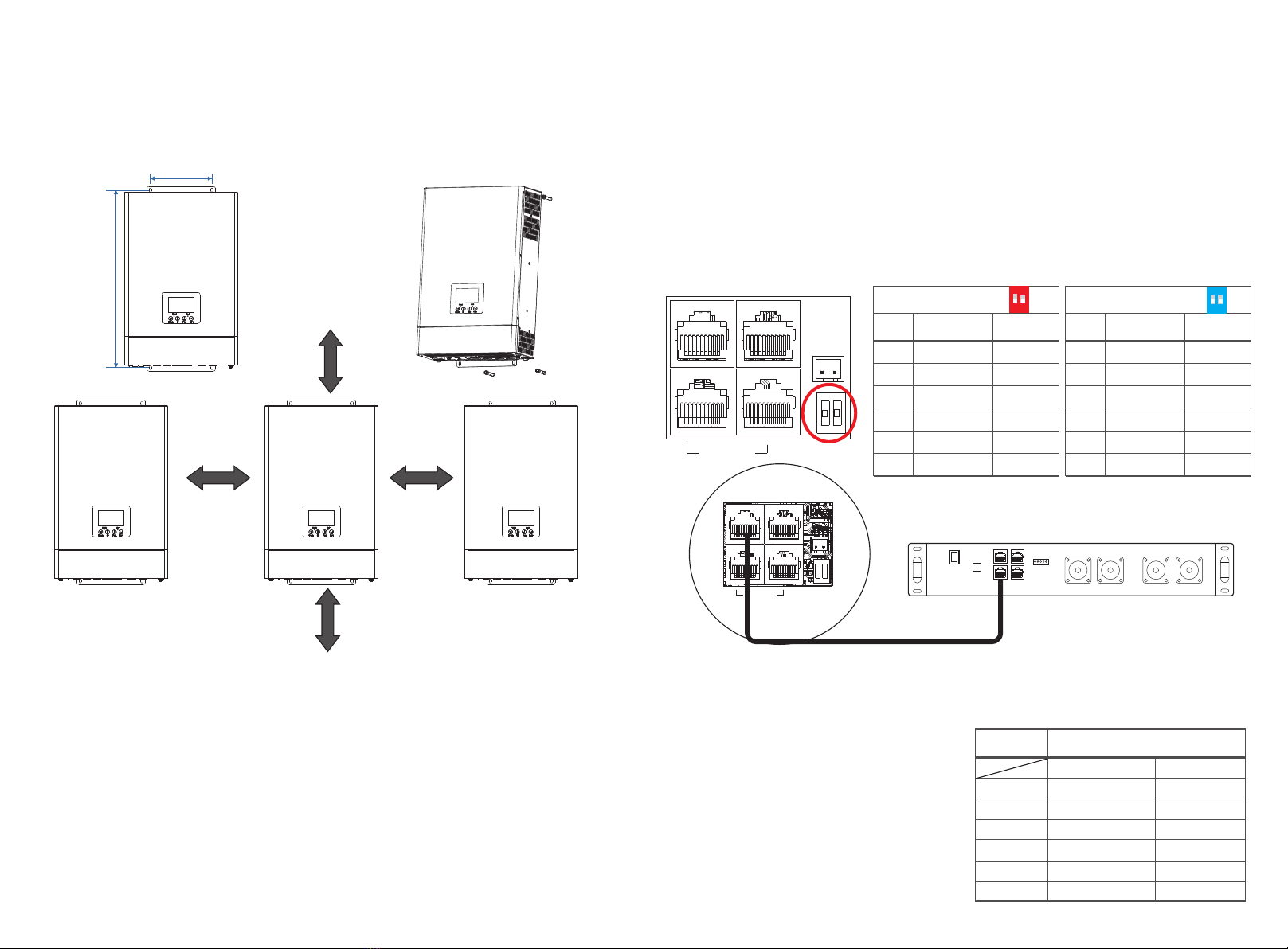
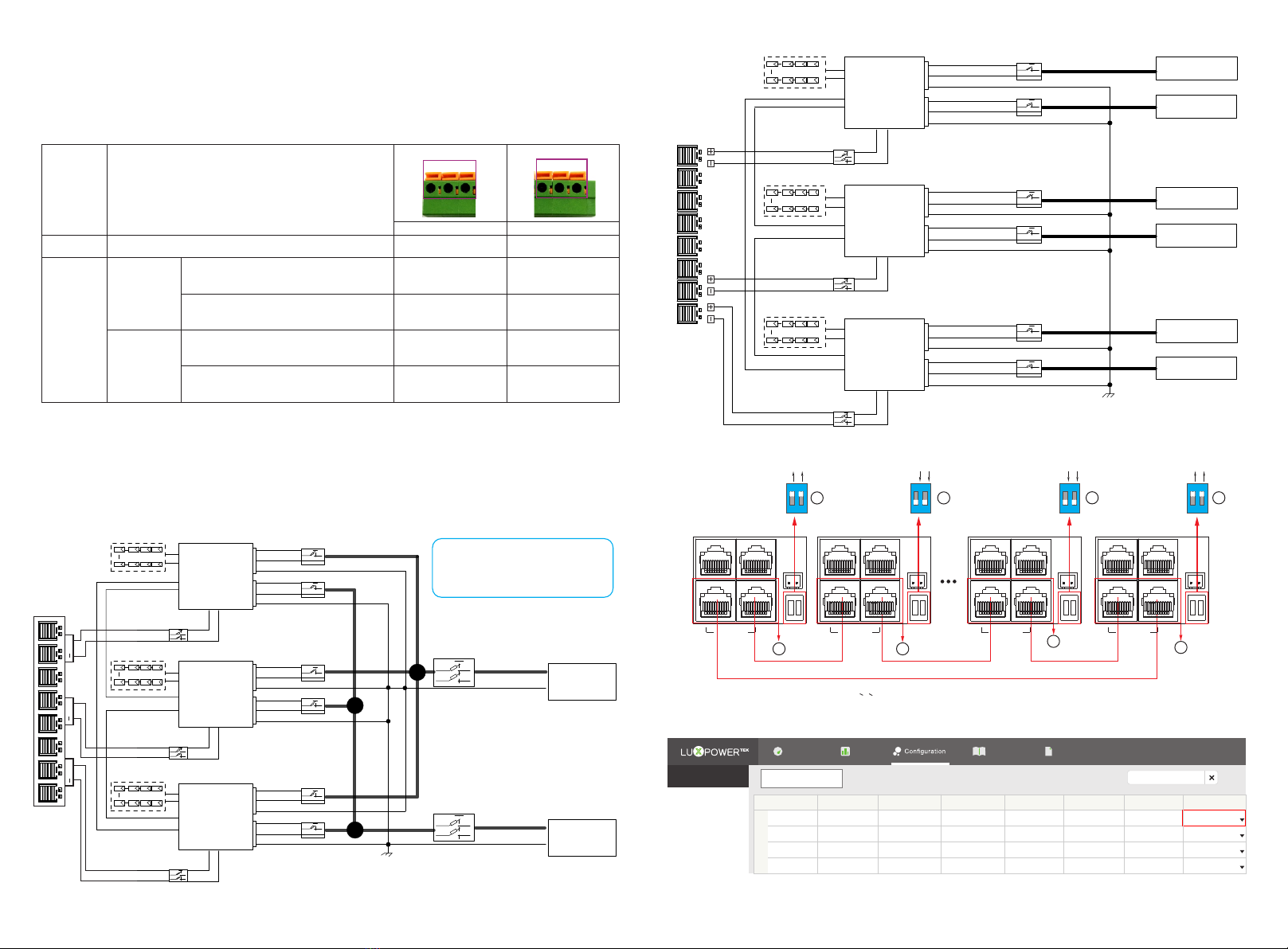
With integrated advanced parallel function, up to 10pcs max paralleling
Support CAN/RS485 for Li-ion battery BMS communication
WIFI/ GPRS remote monitoring , setting and firmware update, support website, free IOS/Android APP
LOGIN
Solar Panel
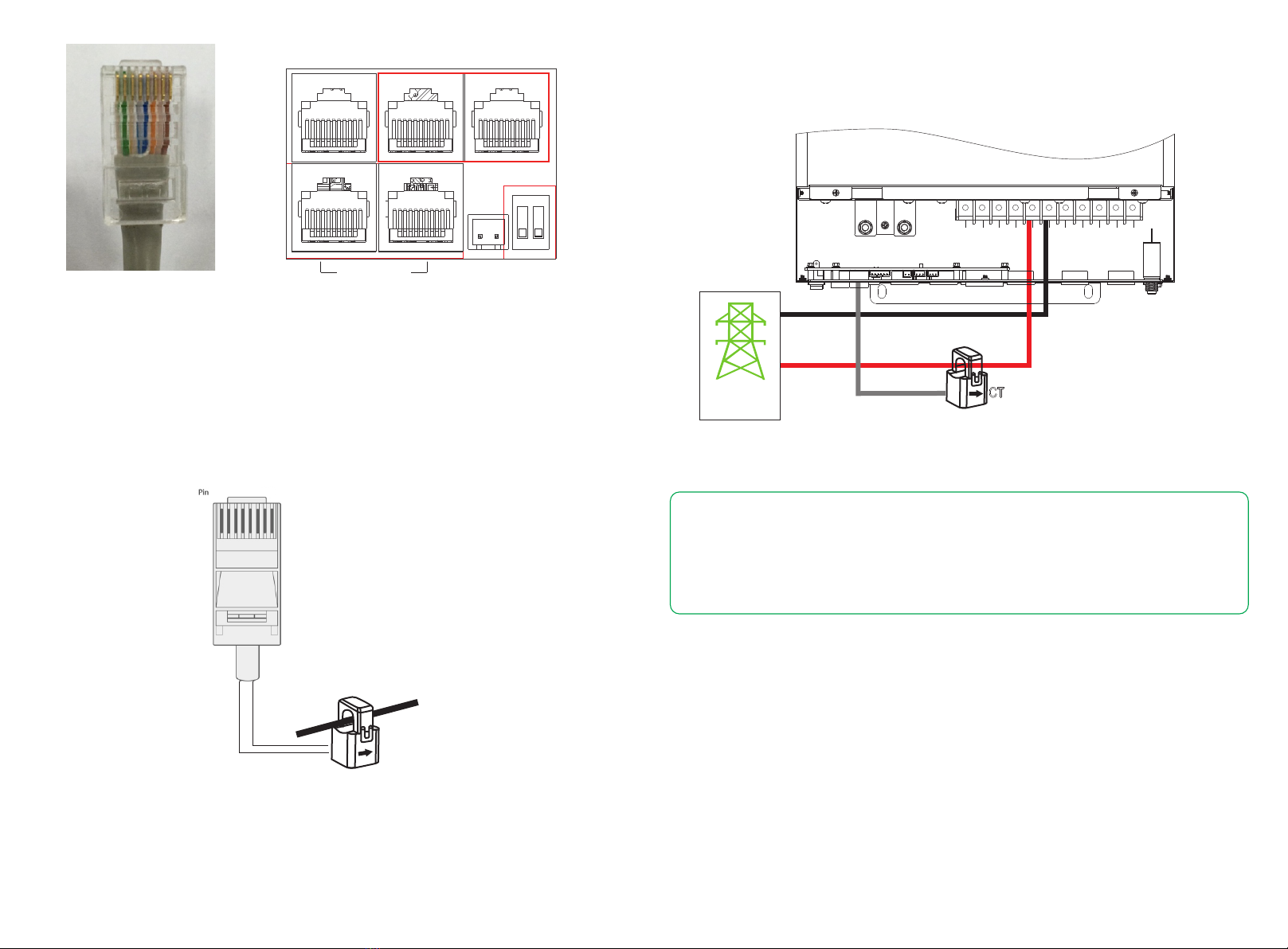
Utility Grid
Generator
Battery
Wifi / 4G Internet Luxpower View
Luxpower Server
Home
Loads
01 02