Lynx P AR 5610 User manual

© 2008-2009 LYNX Technik AG all rights reserved
Reference Manual
P AR 5610
Aspect Ratio Converter with
optional UP/DOWN/CROSS Conversion
Revision 1.1 - January 2009
This Manual Supports Device Revisions:
P AR 5610 Firmware Revision
282
Control System GUI Release
4.4.0
Information in this document is subject to change without notice. No part of this document may be reproduced or
transmitted in any form or by any means, electronic or mechanical for any purpose, without express written permission of
LYNX Technik AG.
LYNX Technik AG may have patents, patent applications, trademarks, copyrights or other intellectual property rights
covering the subject matter in this document. Except as expressly written by LYNX Technik AG, the furnishing of this
document does not give you any license to patents, trademarks, copyrights or other intellectual property of LYNX Technik
AG or any of its affiliates.
LYNX Technik AG
Brunnenweg 3
D 64331 Weiterstadt
Germany
www.lynx-technik.com

P AR 5610 Reference Manual. Rev 1.1
Page 2 of 35
Contents
WARRANTY.................................................................................................................................... 4
REGULATORY INFORMATION..................................................................................................... 5
Europe......................................................................................................................................... 5
Declaration of Conformity ....................................................................................................... 5
USA 5
FCC 47 Part 15....................................................................................................................... 5
GETTING STARTED....................................................................................................................... 6
Packaging.................................................................................................................................... 6
ESD Warning............................................................................................................................... 6
Preventing ESD Damage............................................................................................................ 6
PRODUCT DESCRIPTION ............................................................................................................. 7
Input Video Formats.................................................................................................................... 7
Output Video Formats................................................................................................................. 7
Audio Processing ........................................................................................................................ 7
DolbyE..................................................................................................................................... 7
ARC (Aspect Ratio Conversion).................................................................................................. 8
Conversion from 16:9 to 4:3 Aspect Ratios............................................................................ 8
Conversions from 4:3 to 16:9 Aspect Ratio............................................................................ 9
ARC Image Size and Positioning............................................................................................ 9
Video Processing ...................................................................................................................... 10
Proc Amp Functions.............................................................................................................. 10
Aperture Correction............................................................................................................... 10
Test Patterns......................................................................................................................... 10
Programmable Video Delay (optional: OC-5610-VDLY) ...................................................... 10
Fixed Delays ......................................................................................................................... 11
GPI Function......................................................................................................................... 12
Freeze input with GPI......................................................................................................................12
GPI Options.....................................................................................................................................12
FUNCTIONAL DIAGRAM............................................................................................................. 13
CONNECTIONS ............................................................................................................................ 13
MODULE LAYOUT ....................................................................................................................... 14
INSTALLATION ............................................................................................................................ 15
FIRMWARE OPTIONS.................................................................................................................. 16
User Setting with GPI Control (OC-5610-USET) ...................................................................... 16
Metadata Option (OC-5610-META) .......................................................................................... 16
Up/Down/Cross Conv. Option (OC-5610-UPXD)...................................................................... 16
Down conversion....................................................................................................................... 16
4:3 Letterbox......................................................................................................................... 16
4:3 Center Cut....................................................................................................................... 16
4:3 Stretch to Fill................................................................................................................... 17
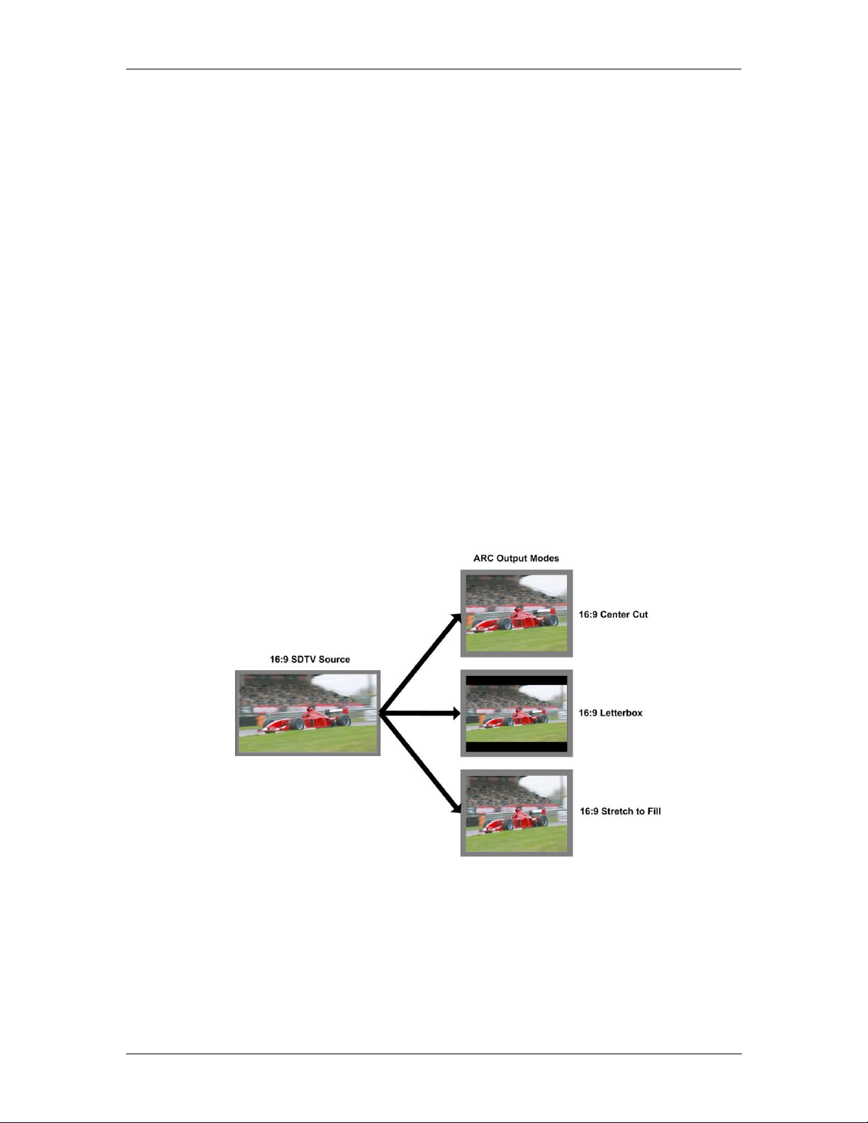
Up Conversion........................................................................................................................... 17
16:9 Center Cut..................................................................................................................... 17
16:9 PillarBox........................................................................................................................ 17
16:9 Stretch to Fill................................................................................................................. 18
Cross Conversion...................................................................................................................... 18
Image size and Positioning ....................................................................................................... 18

P AR 5610 Reference Manual. Rev 1.1
Page 3 of 35
Color Space Conversion ........................................................................................................... 18
SETTINGS AND CONTROL......................................................................................................... 19
Multi Function Switch ................................................................................................................ 19
Using the Local Display Menus................................................................................................. 19
Menu Structure.......................................................................................................................... 20
LED STATUS INDICATORS......................................................................................................... 23
SDI in Status LED 1 .................................................................................................................. 23
ALARM LED.............................................................................................................................. 23
CONTROL SYSTEM GUI.............................................................................................................. 24
Main Tab ................................................................................................................................... 25
Signal Routing....................................................................................................................... 25
Video Proc Tab.......................................................................................................................... 26
Device Status........................................................................................................................ 26
High Quality Up and Cross Conversion (OC-5610-XUPD)....................................................... 27
Input Aspect Ratio................................................................................................................. 27
Output Format....................................................................................................................... 27
Conversion Mode.................................................................................................................. 28
Input Cropping ...................................................................................................................... 28
Output Insertion .................................................................................................................... 28
Output Proc Tabs...................................................................................................................... 28
Color Space Conversion....................................................................................................... 29
Aperture Correction............................................................................................................... 29
H and V Blanking .................................................................................................................. 29
Video Delay Adjustment (optional: OC-5610-VDLY)............................................................ 29
Settings................................................................................................................................. 29
Freeze Mode......................................................................................................................... 30
Test Pattern Pre-select......................................................................................................... 30
Test Pattern Standard........................................................................................................... 30
Test Pattern Enable .............................................................................................................. 30
Video Adjustments................................................................................................................ 31
User Presets (optional: OC-5610-USET).................................................................................. 31
Options Tab............................................................................................................................... 32
Events Tab ................................................................................................................................ 33
SPECIFICATIONS......................................................................................................................... 34
SERVICE....................................................................................................................................... 35
Parts List ................................................................................................................................... 35
Technical Support ..................................................................................................................... 35
CONTACT INFORMATION........................................................................................................... 35

P AR 5610 Reference Manual. Rev 1.1
Page 4 of 35
Warranty
LYNX Technik AG warrants that the product will be free from defects in materials
and workmanship for a period of two (2) years from the date of shipment. If this
product proves defective during the warranty period, LYNX Technik AG at its
option will either repair the defective product without charge for parts and labor,
or will provide a replacement in exchange for the defective product.
In order to obtain service under this warranty, customer must notify LYNX
Technik of the defect before expiration of the warranty period and make suitable
arrangements for the performance of service. Customer shall be responsible for
packaging and shipping the defective product to the service center designated by
LYNX Technik, with shipping charges prepaid. LYNX Technik shall pay for the
return of the product to the customer if the shipment is within the country which
the LYNX Technik service center is located. Customer shall be responsible for
payment of all shipping charges, duties, taxes and any other charges for
products returned to any other locations.
This warranty shall not apply to any defect, failure, or damage caused by
improper use or improper or inadequate maintenance and care. LYNX Technik
shall not be obligated to furnish service under this warranty a) to repair damage
resulting from attempts by personnel other than LYNX Technik representatives to
install, repair or service the product; b) to repair damage resulting from improper
use or connection to incompatible equipment; c) to repair any damage or
malfunction caused by the use of non LYNX Technik supplies; or d) to service a
product which has been modified or integrated with other products when the
effect of such modification or integration increases the time or difficulty servicing
the product.
THIS WARRANTY IS GIVEN BY LYNX TECHNIK WITH RESPECT TO THIS
PRODUCT IN LIEU OF ANY OTHER WARRANTIES, EXPRESS OR IMPLIED.
LYNX TECHNIK AND ITS VENDORS DISCLAIM ANY IMPLIED WARRANTIES
OF MERCHANTABILITY OR FITNESS FOR A PARTICULAR PURPOSE. LYNX
TECHNIK`S RESPONISIBILITY TO REPAIR AND REPLACE DEFECTIVE
PRODUCTS IS THE SOLE AND EXCLUSIVE REMEDY PROVIDED TO THE
CUSTOMER FOR BREACH OF THIS WARRANTY. LYNX TECHNIK AND ITS
VENDORS WILL NOT BE LIABLE FOR ANY INDIRECT, SPECIAL,
INCIDENTIAL, OR CONSEQUENTIAL DAMAGES IRRESPECTIVE OF
WHETHER LYNX TECHNIK OR THE VENDOR HAS ADVANCE NOTICE OF
THE POSSIBILITY OF SUCH DAMAGES.

P AR 5610 Reference Manual. Rev 1.1
Page 5 of 35
Regulatory information
Europe
Declaration of Conformity
USA
FCC 47 Part 15
This device complies with part 15 of the FCC Rules. Operation is subject to the following
two conditions: (1) This device may not cause harmful interference, and (2) this device
must accept any interference received, including interference that may cause undesired
operation.
Note: This equipment has been tested and found to comply with the limits for a Class A
digital device, pursuant to the part 15 of the FCC Rules. These limits are designed to
provide reasonable protection against harmful interference when the equipment is
operated in a commercial environment. This equipment generates, uses, and can radiate
radio frequency energy and, if not installed and used in accordance with the instruction
manual, may cause harmful interference to radio communications. Operation of this
equipment in a residential area is likely to cause harmful interference in which case the
user will be required to correct the interference at his own expense
We LYNX Technik AG
Brunnenweg 3
D-64331 Weiterstadt
Germany
Declare under our sole responsibility that the product
TYPE: P AR 5610
To which this declaration relates is in conformity with the following
standards (environments E1-E3):
EN 55103-1 /1996
EN 55103-2 /1996
EN 60950 /2001
Following the provisions of 89/336/EEC and 73/23/EEC directives.
Winfried Deckelmann
Weiterstadt, November 2008
Place and date of issue Legal Signature

P AR 5610 Reference Manual. Rev 1.1
Page 6 of 35
Getting Started
Most CardModules are installed into the rack frames and system tested in the factory. If
this is an upgrade part or service exchange item then the module is supplied in a padded
cardboard carton which includes the CardModule, rear connection plate and mounting
screws.
Packaging
The shipping carton and packaging materials provide protection for the module during
transit. Please retain the shipping cartons in case subsequent shipping of the product
becomes necessary. Do not remove the module from its protective static bag unless
observing adequate ESD precautions. Please see below.
ESD Warning
This product is static sensitive. Please use caution and use preventative measures to
prevent static discharge or damage could result to module.
Preventing ESD Damage
Electrostatic discharge (ESD) damage occurs when electronic assemblies or the
components are improperly handled and can result in complete or intermittent failure.
Do not handle the module unless using an ESD-preventative wrist strap and ensure that
it makes good skin contact. Connect the strap to any solid grounding source such as any
exposed metal on the rack chassis or any other unpainted metal surface.
Caution
Periodically check the resistance value of the antistatic strap. The measurement should
be between 1 and 10 Megohms.

P AR 5610 Reference Manual. Rev 1.1
Page 7 of 35
Product Description
The P AR 5610 module is a high performance Aspect Ratio Converter with optional Up-
/Down- and Cross Conversion.
Firmware options provide the ability to easily add additional options which includes:
•12 frames video delay (option code OC-5610-VDLY)
•HQ Up/Down/Cross Conversion (option code OC-5610-UPXD)
•Stored module presets with GPI recall (option code OC-5610-USET)
•Metadata Option (AFD/Closed Captions/Timecode) (option code OC-5610-META)
Firmware options can be added at any time with a license code. No hardware or
Firmware modifications are required.
Input Video Formats
The module has one multi-format serial digital input with automatic input detection. The
module will detect the following input standards and configure the input stage
automatically for operation in the connected format.
SDTV Formats
HDTV Formats
525 / 59.94Hz
1080i / 59.94Hz
625 / 50Hz
1080i / 60Hz
1080i / 50Hz
720P / 59.94Hz
720P / 60Hz
720P / 50Hz
Output Video Formats
The module provides four SDI outputs, user assignable in two sets of two outputs; these
sets can be mapped independently to any of the two internal channels. Supported output
video formats are:
SDTV Formats
HDTV Formats
525 / 59.94Hz
1080i / 59.94Hz
625 / 50Hz
1080i / 60Hz
1080i / 50Hz
720P / 59.94Hz
720P / 60Hz
720P / 50Hz
The output format frequency (or frame rate) is determined by the frame rate of the input
signal.
Audio Processing
The module will de-embed the complete audio payload from the incoming SDI stream (4
AES groups = 8 AES = 16 audio channels) and re-embed the audio with a matching
delay, which compensates for the video delay in this module.
DolbyE
Note. The module will support DolbyE in a future release. When implemented the module
will not be providing DolbyE encoding or decoding capability, but have the capability to
de-embed synchronize / delay and re-embed any existing DolbyE signals through the
module transparently (while preserving guard band timing).

P AR 5610 Reference Manual. Rev 1.1
Page 8 of 35
ARC (Aspect Ratio Conversion)
The module provides one High Quality ARC (Aspect Ratio Converter) which can be used
to convert SDTV signals between 4:3 or 16:9 aspect ratios. This ARC is a high quality
image processor which has extended functionality including manually adjustable image
size and position.
Modes supported are as follows:
Conversion from 16:9 to 4:3 Aspect Ratios
4:3 Letterbox
This takes the 16:9 aspect ratio of the input signal and fits it horizontally into the 4:3 SD
image area with black bars at the top and bottom of the image.
4:3 Center Cut
This mode cuts the center portion of the 16:9 input signal and fills the 4:3 SD image area
4:3 Stretch to Fill
This mode takes the 16:9 input signal and distorts (vertically stretches) the image to fit
the available 4:3 SD image area.

P AR 5610 Reference Manual. Rev 1.1
Page 9 of 35
Conversions from 4:3 to 16:9 Aspect Ratio
16:9 PillarBox
This takes the 4:3 aspect ratio of the input signal and fits it vertically into the 16:9 SD
image area with black bars at the left and right of the image.
16:9 Center Cut
This mode cuts the horizontal center portion of the 4:3 input signal and fills the 16:9 SD
image area (cropping the top and bottom of the image)
16:9 Stretch to Fill
This mode takes the 4:3 input signal and distorts (horizontally stretches) the image to fit
the available 16:9 SD image area
ARC Image Size and Positioning
The single high quality ARC provides the ability to manually adjust image position and
size during the conversion process. Please refer to the GUI section of this manual for
more information of the controls provided and how to use them.

P AR 5610 Reference Manual. Rev 1.1
Page 10 of 35
Video Processing
Proc Amp Functions
Each of the two output channels has an associated video proc amp which provides user
adjustable Gain / Saturation / Black Level and Hue using on screen sliders.
Aperture Correction
An adjustable horizontal aperture corrector is provided for each of the two output
channels. This can be used to add (or remove) image sharpness as required.
Note. When using the down converter the filtering process results in a very slight
loss of high frequency information (which is normal), the aperture corrector can
be used to compensate for this slight loss.
Test Patterns
Each of the two output channels has its own independent test pattern generator which
provides a wide selection of test patterns which can be switched into each output. (The
Test pattern will follow the selected output standard selected for each channel).
The selected test pattern is also available as one of the modes the synchronizer will
switch to when excessive video TRS errors are encountered. Possible synchronizer
actions when the input video errors become excessive are:
•Freeze Field 1
•Freeze Field 2
•Freeze Frame
•Selected Test Pattern
•Black
Programmable Video Delay (optional: OC-5610-VDLY)
Each of the two SDI outputs has separate programmable video delays which can be set
(independently) between 0 and 12 frames (max). The adjustment is available in pixel, line
and full frame increments.
Note The ARC (including the OC-5610-UPXD option, if installed) has fixed frame
delays depending on the signal path and selected function (see below). The 0 >
12 frame user adjustment is additional delay relative to the fixed delays.
This adjustment will delay the video output relative to the connected reference by the
delay setting specified. (+ fixed delay)

P AR 5610 Reference Manual. Rev 1.1
Page 11 of 35
Fixed Delays
The ARC (including the OC-5610_VDLY and OC-5610_UPXD options, if installed) has
fixed frame delays depending on the signal path and selected function - see below :
SDI Input
SDI Output
Delay[frames]
Timing = 0
Delay[ms]
Timing = 0
No Conversion
525
525
1
33
625
625
1
40
1080i50
1080i50
1
40
1080i59.94
1080i59.94
1
33
720p50
720p50
1 (p)
20
720p59,94
720p59,94
1 (p)
16
SDTV Aspect Ratio Conversion
525
525
2
66
625
625
2
80
Down Conversion (if OC-5610_UPXD option is installed)
1080i50
625
3
120
1080i59.94
525
3
99
720p50
625
2
80
720p59,94
525
2,5
82
Up Conversion (if OC-5610_UPXD option is installed)
525
720p59,94
3 (p)
49
525
1080i59,94
2
66
625
720p50
3 (p)
60
625
1080i50
2
80
Cross Conversion (if OC-5610_UPXD option is installed)
1080i50
720p50
4 (p)
80
1080i59.94
720p59,94
4 (p)
66
720p50
1080i50
1,5
60
720p59,94
1080i59,94
2
66

P AR 5610 Reference Manual. Rev 1.1
Page 12 of 35
GPI Function
The GPI input (General Purpose Input) which is a switch input function (contact closure)
can be used to perform a number of functions. The influence of this input can be set by
the user using the control system on the Video Proc Tab.
Freeze input with GPI
If this mode of the GPI influence is selected then the following functions will be
performed:
•With GPI open the module processes the input signal as usual
•With GPI closed the input will be frozen (volatile freeze, i.e. frozen frame is not
retained through power cycle)
In the case of an activated freeze the module processing performs all functions on the
frozen frame.
GPI Options
The GPI functionality can be enhanced with the addition of the OC-5610-USET firmware
option. This allows the user to store 4 complete sets of module settings (snapshots) in
module flash ram. The GPI can then be configured to toggle between any 2 of the 4
stored presets if required.

P AR 5610 Reference Manual. Rev 1.1
Page 13 of 35
Functional Diagram
A functional diagram of the P AR 5610 is shown below.
Connections
Video
The P AR 5610 uses standard 75 Ohm BNC connectors. We recommend the use of high
quality video cable for digital video connections to reduce the risk of errors due to
excessive cable attenuation. Max cable lengths the module will support are shown below.
SDTV = 250m Belden 8281 (270Mbits/s)
HDTV = 140m Belden 1694A (1.4Gbits/s)
Note. Due to the compact design of the connection plate it will be necessary to
use a connection tool to secure the BNC video connectors.

P AR 5610 Reference Manual. Rev 1.1
Page 14 of 35
Module Layout
Module Front Panel Module Rear Termination Panel
Note. Cooling fan operation is monitored and alarmed with the module alarm
LED and also within the LYNX control system.
Cooling Fans

P AR 5610 Reference Manual. Rev 1.1
Page 15 of 35
Installation
If this module was supplied as part of a system it is already installed in the rack
enclosure. If the module was supplied as a field upgrade please follow the installation
procedure below.
NOTE Observe static precautions when handling card. Please see ESD
warnings on Page 5.
This module has a double width rear connection panel, meaning it will occupy two slots of
a standard Series 5000 Card Rack. This is to accommodate the additional connections
needed for this module and to also provide adequate space for cooling in the rack. Up to
five P AR 5610 modules can be accommodated in a single Series 5000 rack frame.
NOTE. When using this module we highly recommend the use of the R FR 5011
Fan Front Rack Frame which provides additional airflow into the rack. If you
plan to install this module into empty slots in an existing rack with no fan front
cover - then please purchase the R FR 5001 Fan Front update kit.
Each Card Module is supplied with a rear connection panel and mounting screws. Please
follow the procedure below for the installation of the card module into the Series 5000
Card Frame.
We recommend you power the rack down before installing any additional modules into an
existing card frame.
1. Select a free two slot space in the card frame where the CardModule will be
located.
2. Remove the blank connection panels from the rear of the rack (if fitted)
3. Install the rear connection panel using the screws supplied. Do not tighten the
screws fully
4. Slide the card module into the card frame and carefully check the CardModule
connects to the rear connection plate. The card should fit easily and should not
require excessive force to insert - if you feel any resistance, there could be
something wrong with the rear connection panel location. Do not try and force
the connection this may damage the connectors. Remove the rear connection
panel and check alignment with the CardModule.
5. Insert and remove the CardModule a few times to ensure correct alignment and
then tighten the two screws to secure the rear connection plate.
6. Power up the rack and check the module LED’s and matrix display illuminate.
Check the module is automatically logged into the control system device tree.
(It may take a few seconds for the control system to “discover” the new module)
NOTE. The use of the optional control system is mandatory for the
control and setup of this module. If you do not have the control system,
then please contact your LYNX representative for details on how to
upgrade your rack with the LYNX control system.

P AR 5610 Reference Manual. Rev 1.1
Page 16 of 35
Firmware Options
The basic module is a single channel SDTV ARC. With the addition of the following
firmware options the performance and features of the module can be greatly enhanced
and tailored to meet a specific application.
Note. Firmware options can be added at any time by simply purchasing and
installing a license code string. No hardware or firmware modifications are
needed.
For information on how to install a licensed option please refer to the GUI section of this
manual.
User Setting with GPI Control (OC-5610-USET)
This module has a wide variety of user settings and configuration possibilities. The
module automatically retains the last used settings in flash ram which will survive power
cycles. The addition of the OC-5610-USET firmware option allows the user to store 4
individual sets of module settings (snapshots) into module flash ram. These can then be
recalled using the control system to quickly re-purpose the modules settings. The GPI
can also be configured to toggle between any 2 of the 4 stored presets if required.
Metadata Option (OC-5610-META)
This option provides support for AFD (automatic format descriptor), closed caption and
also Timecode. The module will process and convert this metadata information between
the input and outputs when installed.
This is future option and more detailed information will be provided at a later date
Up/Down/Cross Conv. Option (OC-5610-UPXD)
The addition of this option provides a single channel of high quality up, down and cross
conversion to the module. Modes of operation are described below.
Note : Operation mode is switchable i.e. Up Conversion OR Down Conversion
OR Cross Conversion OR Aspect Ratio Conversion
Down conversion
Modes of operation are described below.
4:3 Letterbox
This takes the 16:9 aspect ratio of the input HD signal and fits it into the 4:3 SD aspect
ratio screen with black bars at the top and bottom of the image.
4:3 Center Cut
This mode cuts the center portion of the 16:9 input signal and fills the 4:3 SD aspect ratio
screen.

P AR 5610 Reference Manual. Rev 1.1
Page 17 of 35
4:3 Stretch to Fill
This mode takes the 16:9 input signal and distorts (vertically stretches) the image to fit
the available 4:3 SD aspect ratio space.
Up Conversion
The UP converter will convert the connected SDTV input standard to the selected HD
Standard within the same frame rate. See below
525 / 59.94Hz Input Signal Converted to 1080i / 59.94Hz or 720P / 59.94Hz
625 / 50Hz Input Signal Converted to 1080i / 50Hz or 720P / 50Hz
Modes of operation are as follows:
16:9 Center Cut
This mode cuts the horizontal center portion of the 4:3 SD input signal and fills the 16:9
HD aspect ratio image area. (top and bottom of image are cropped)
16:9 PillarBox
This takes the 4:3 SD aspect ratio of the input signal and fits it vertically into the 16:9 HD
image area with black bars at the left and right of the image.
16:9 HDTV Source
4:3 Center Cut
4:3 Letterbox
4:3 Stretch to fill

P AR 5610 Reference Manual. Rev 1.1
Page 18 of 35
16:9 Stretch to Fill
This mode takes the 4:3 SD input signal and distorts (horizontally stretches) the image to
fit the available 16:9 HD image area.
Cross Conversion
When used in cross conversion mode the module will cross convert the video signal
between 1080i and 720P formats within the same frame rate.
Image size and Positioning
This option also provides the ability to manually adjust the image size and position of the
converted output. For more information on the controls and use of this feature please
refer to the GUI section of this manual for more details.
Color Space Conversion
The conversion options also provide integrated color space conversion capability which
will automatically compensate for the conversion of the wider 709 HD color space into the
more narrow 601 SDTV color space or vice versa ensuring legal color reproduction.
NOTE. Color space conversion can be bypassed or set to only process
chrominance if desired.

P AR 5610 Reference Manual. Rev 1.1
Page 19 of 35
Settings and Control
The P AR 5610 module has an integrated micro-controller, which enables the module to
be configured and controlled locally using the multifunction switch and 4 character dot
matrix display, or from remote using a GUI interface when using one of the optional
controllers and control software.
NOTE. This module is extremely compact and flexible with hundreds of possible
user settings. It is not practical to make all these settings available on the local
dot matrix display. The use of the control system is mandatory to access the
vast array of settings possible. Please refer to the GUI section of this manual for
details on the control provided. Some basic module settings are possible via the
local controls, which are detailed below.
Once set, all settings are automatically saved in non-volatile internal memory. (Flash
RAM) The module will always recall the last used settings.
Multi Function Switch
The CardModule is equipped with a multi-function switch located on the front bottom
edge of the card. (See above)
Using the Local Display Menus
Making local adjustments to the module is done using the multifunction switch and the
integrated 4-character dot matrix display. The menu system is layered, and navigation
through the system is done using the UP and DOWN functions of the switch. ENTER is
used to move between menu levels and also enter a selection.
Up Down Enter
Switch Operations
Multi-function Switch
Side Front
Switch Function
Operation
UP
Move UP within a level
DOWN
Move down within a level
ENTER
Change levels / Make selection
!

P AR 5610 Reference Manual. Rev 1.1
Page 20 of 35
Menu Structure
The Menu structure is defined in the next table, and can be used to help navigating
through the menu system.
ENTER moves between levels
UP/DOWN moves between items within the level
When a new setting is entered the system will jump back one level in the menu system.
•The “back” selection in the menu structure will take you back one level when
selected.
•When an item is selected which has several setting possibilities the first value
displayed will be the value currently stored in the system. The order of the
available settings for any menu item in the table supplied does not represent the
order the settings will actually be displayed.
•If left unattended, the menu will default to the root display after a short timeout.
Layer 1
Layer 2
Layer 3
Layer 4
Layer 5
Description
PAR 5610
Root Display
OUT1/2
Output Select
INPT
Input to output select
Conv
Converter Output
No C
No Converter
back
DEL
Delay adjustment
FRAM
Frame Delay
0000
LINE
Line Delay
0000
PIX
Pixel Delay
0000
back
APRT
Apperture Correction
ENAB
Enable
ON
OFF
back
LEVL
Level
+/- 000
back
TEST
Testpattern Settings
ENAB
Enable
Table of contents
Other Lynx Media Converter manuals

Lynx
Lynx MiniModules 3000 Series User manual

Lynx
Lynx C DA 5005 User manual

Lynx
Lynx C AD 5110 User manual

Lynx
Lynx C AD 5320 D User manual

Lynx
Lynx D AD 3260 BS User manual

Lynx
Lynx Hilo Preliminary User manual

Lynx
Lynx yellobrik CDH 1813 User manual

Lynx
Lynx C AD 3110-2 User manual

Lynx
Lynx hilo User manual

Lynx
Lynx C AD 3321 D User manual

Lynx
Lynx C DA 3002 User manual

Lynx
Lynx greenMachine HDR Static User manual

Lynx
Lynx hilo User manual

Lynx
Lynx C DX 5624 User manual

Lynx
Lynx CardModule C AD 5131 User manual

Lynx
Lynx C AD 3100 User manual

Lynx
Lynx Aurora User manual

Lynx
Lynx C AD 5111 User manual

Lynx
Lynx C DA 5010 User manual

Lynx
Lynx C DX 5024 C User manual