M-Elec GD-5510 -01 User manual
-phase Stepping Motor Drive
r
GD-5510 -01
Instructions Manual
(
For desi
g
ners' use
)
MN0208-1

GD-5510-01
Instructions Manual
Introduction
This Instructions Manual describes the safe and proper method of handling
"5-phase Stepping Motor Driver GD-5510-01" with emphasis on the specifications,
assuming that our readers are engaged in designing of control devices
incorporating stepping motors.
Please ensure to read and understand this Instructions Manual
before using the product.
Please keep this Instructions Manual at hand
so that it is always available for reference.
-2-

GD-5510-01
Instructions Manual
Descriptions in this manual on safety matters:
This product must be operated and used properly.
Otherwise, or when it is operated and used erroneously, unforeseen accidents
may occur, causing physical injuries or property damages.
Majority of these accidents can be avoided if you are well informed of
hazardous circumstances in advance.
Consequently, this instructions manual describes all the hazardous and
dangerous circumstances and situations which can be foreseen and anticipated
as well as necessary precautions.
All the above descriptions are being titled by the following symbol-marks and
signal-words, namely:
Represents warnings ignorance of which can cause accidents
involving fatal or serious physical injuries, or death.
Represents cautions ignorance of which can cause accidents
involving minor physical injuries or property damages.
-3-

GD-5510-01
Instructions Manual
Introduction
Descriptions in this manual on safety matters:
CONTENTS PAGE
1. Safety
1-1. Safety Precautions 6
1-2. Safety Information for Handling 7
Overview
2-1. Characteristics 11
2-2. Product Configuration 11
2-3. Appearance 11
3. Name and Function of Each Section
3-1. Signal I/O Connector(J1) 12
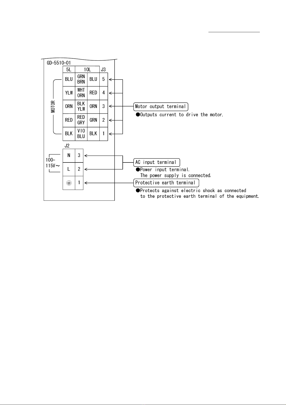
3-2. AC Input/Motor Output Terminal Block(J2, J3) 13
3-3. Operating Section 14
3-4. POWER LED 14
3-5. O.H.A LED 14
4. Function Set-up by Use
4-1. Setting MOTOR SELECT switch 15
4-2. Setting HIGH-SPEED POWER OUTPUT SELECT switch 15
4-3. Setting STEP ANGLE SELECT switch 16
4-4. Setting HOLD CURRENT SELECT switch 17
4-5. Setting DRIVE CURRENT SELECT switch 18
4-6. Setting HOLD SWITCHING TIME SELECT switch 19
4-7. Setting ROTATE CHARACTERISTIC SELECT switch 19
4-8. Setting PULSE INPUT TYPE SELECT switch 20
5. Installation
5-1. Conditions for Installation 21
5-2. Mounting Method 22
6. Connection
6-1. Overview of Connection Configuration 23
6-2. Connecting Signal I/O Connector(J1) 24
6-3. Connecting AC Input/Motor Output Terminal Block(J2, J3) 25
6-4. Inputting Power 27
7. Confirmation of Setting and Connection
7-1. Check Points 28
2.
-4-

GD-5510-01
Instructions Manual
PAGE
8. Maintenance and Check-up
8-1. Maintenance and Check-up 29
8-2. Troubleshooting 30
9. Storing and Disposal
9-1. Storing 31
9-2. Disposal 31
10. Specifications
10-1. General Specifications 32
10-2. Conforming to Europe standards and UL standards 33
10-3. I/O Signal
(1) Example Circuit Connection 34
(2) Drive pulse input (CW,CCW) 35
(3) Motor excitation stop input (M.F) 36
(4) Phase signal output (P.O) 37
(5) Overheat alarm signal output (O.H.A) 38
(6) Step angle switch input (C.S) 39
10-4. Dimensions 40
10-5. Applicable Motors 41
10-6. Torque Characteristics 42
The main parts which revised by this manual
-5-

GD-5510-01
Instructions Manual
1.Safety
1-1.Safety Precautions
(1) This product is not designed or manufactured for application for equipment
requiring high level of reliability such as equipment related to nuclear
energy, aeronautics-related equipment, automobiles, ships, medical appliances
directly handling the human body and equipment that might seriously affect
properties.
(2) Do not use or keep the product in explosive or corrosive environments,
in the presence of flammable gases, locations subjected to splashing water,
fine particles, soot, steam, or exposed to radiation or direct sunshine.
Doing so may cause electric shock, injury or fire.
(3) Do not transport, move, install the product, perform connections or inspections
when the power is on.
Doing so may cause electric shock.
(4) Only qualified personnel are allowed to transport, move, install the product,
perform connections or inspections.
Failure to do so may cause electric shock, injury or fire.
(5) This product is for a devices inclusion.
Please establish it into enclosure without fail.
Be sure to ground the protective earth terminal of the driver.
(6) Do not touch the driver during operation or immediately after stopping.
Doing so may cause burn on the skin due to overheating of the driver.
(7) Ensure to use this product according to the method specified
in the Instructions Manual and within the specifications.
(8) Depending on the operational conditions, the stepping motor may step out when
it is on holding-state or driving-state.
In particular, the load in transport may fall if the motor steps out on the
vertical drive (such as the Z-axis).
Start operation after test run for deliberate confirmation of operation.
(9) Provide fail-safe measures so that the entire system may operate in a safe
mode even in cases of the external power supply failure, disconnection of the
signal line, or any failure on the driver.
-6-

GD-5510-01
Instructions Manual
1-2.Safety Information for Handling
●Overall:
Use only an insulated screwdriver to
adjust or set internal switches.
Failure to do so may cause electric shock.
Do not touch the driver during operation
or immediately after stopping.
Doing so may cause burn on the skin due to
overheating of the driver.
●When connecting the AC Input/Motor Output Terminal Block (J2, J3):
Turn the main power OFF.
Failure to do so may cause electric shock.
Securely ground the protective earth
terminal .
Failure to do so may cause electric shock.
Do not force the power line or the motor
line to be bent or pulled or pinched.
Doing so may cause electric shock or fire.
Erroneous connection may result
in breakage of the motor or the driver.
Correctly connect the motor wiring.
-7-

GD-5510-01
Instructions Manual
●When setting up the MOTOR SELECT switch:
Erroneous setting may cause burn on the
skin due to overheating of the motor.
Ensure correct setting.
●When setting up the STEP ANGLE SELECT switch:
Erroneous setting may cause breakage of
the machine or injury due to unexpected
rotation of the motor.
Ensure correct setting.
●When setting up the HOLD CURRENT SELECT switch:
A high setting value may cause burn on the
skin due to overheating of the motor.
Do not select a high value beyond the
required.
●When setting up the DRIVE CURRENT SELECT switch:
Erroneous setting may cause burn on the
skin due to overheating of the motor.
Ensure correct setting.
●When inputting the motor excitation stop (M.F) signal:
Deterioration of the holding power with
the motor may cause breakage of machine
or injury.
Check safety before inputting.
-8-

GD-5510-01
Instructions Manual
●When setting up PULSE INPUT TYPE SELECT switch:
Erroneous setting may cause breakage of
the machine or injury due to unexpected
rotation of the motor.
Ensure correct setting.
●When installing:
Mount it on a noncombustible member.
Keep it away from combustibles.
Overheating may cause fire.
●When inputting power:
Do not contact with a wet hand.
Doing so may cause electric shock.
The marks, and , on the front panel
indicate terminals on which power voltage
is applied.
Do not touch such terminals while
inputting power and while POWER LED is on.
Doing so may cause electric shock.
Unexpected behavior of the motor may cause
breakage of the machine or injury.
Maintain the state where emergency stop is
enabled at any time.
●When the overheat alarm (O.H.A) signal is output:
Overheating may cause fire.
Stop operation upon output of this signal.
-9-

GD-5510-01
Instructions Manual
●When performing maintenance and checking:
Only qualified personnel are allowed to
perform maintenance and checking.
Failure to do so may cause electric shock.
Do not contact with a wet hand.
Doing so may cause electric shock.
The marks, and , on the front panel
indicate terminals on which power voltage
is applied.
Do not touch such terminals while
inputting power and while POWER LED is on.
Doing so may cause electric shock.
Do not replace fuse.
Do not disassemble, repair or modify.
Doing so may cause electric shock, injury
or fire.
-10-

GD-5510-01
Instructions Manual
2.
O
verv
i
ew
2-1.Characteristics
GD-5510-01 is a driver for a 5-phase stepping motor with single-phase 100-115V input.
It can drive a 5-phase stepping motor ranging from 0.75A/phase ~ 1.4A/phase.
Ten step angles can be selected from angles ranging from a 1/1 division to
a 1/800 division of the basic angle.
HOLD CURRENT and DRIVE CURRENT can be set up.
HIGH-SPEED TORQUE can be selected for the motor.
● Applicable motors and setting for each motor are given in the table
"10-5. Applicable Motors".
2-2.Product Configuration
The product consists of the main frame and the accessories.
● GD-5510-01 One unit
(Complete with terminal block covers)
● Housing for J1 (51103-1200:Molex) One unit (accessory)
● Contact for J1 (50351-8100:Molex) 14 contacts (accessories,2 for spares)
2-3.Appearance
-11-

GD-5510-01
Instructions Manual
3.Name and Function of Each Section
3-1.Signal I
/
O Connector(J1)
CW+
J1
●Directs the motor to operate CW.
●Shuts off output current to drive the motor.
●Outputs the signal when internal temperature
of the driver has reached approx. 70℃ or more.
1
Motor excitation stop signal input terminal
Step angle switch signal input terminal
Phase signal output terminal
Overheat alarm signal output terminal
CW drive pulse signal input terminal
R.GND
GD-5510-01
●Switches the step angle by 1/20 division.
●Outputs the signal when the motor-excitation
state is the excitation home position.
CW-
CCW+
CCW-
M.F+
M.F-
C.S+
C.S-
R.GND
2
3
4
5
6
7
8
9
10
11
12
P.O
O.H.A
GND terminal for P.O signal
CCW drive pulse signal input terminal
●Directs the motor to operate CCW.
GND terminal for O.H.A signal
-12-
GD-5510-01
Instructions Manual
3-2.AC Input
/
Motor Output Terminal Block(J2,J3)
-13-
GD-5510-01
Instructions Manual
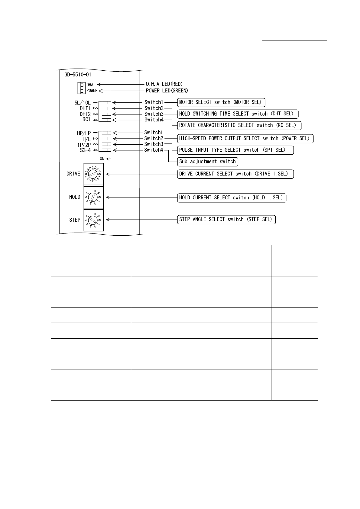
3-3.Operation Section
3-4.POWER LED
POWER LED (GREEN) comes on upon inputting power.
3-5.O.H.A LED
O.H.A LED(RED)comes on when internal temperature
of the driver has reached approx. 70℃ or more.
Name of Operation Section Function Factory
Setting
MOTOR
SELECT switch Selects the applicable motor. 〔10L〕
HIGH-SPEED POWER OUTPUT
SELECT switch Selects HIGH-SPEED TORQUE for the motor. 〔LP,L〕
Sub adjustment
switch Please use it with OFF. 〔OFF〕
PULSE INPUT TYPE
SELECT switch 〔2P〕 Selects a pulse input type.
〔OFF,OFF〕
ROTATE CHARACTERISTIC
SELECT switch Selects a characteristic of motor rotation. 〔OFF〕
HOLD SWITCHING TIME
SELECT switch
DRIVE/HOLD CURRENT automatic switching time
is selected.
STEP ANGLE
SELECT switch Selects a step angle. 〔No.1〕
Selects HOLD CURRENT. 〔No.3〕
〔No.F〕
HOLD CURRENT
SELECT switch
DRIVE CURRENT
SELECT switch Selects DRIVE CURRENT.
-14-

GD-5510-01
Instructions Manual
4.Function Set-up by Use
4-1.Setting MOTOR SELECT switch
Erroneous setting may cause burn on the
skin due to overheating of the motor.
Ensure correct setting.
The MOTOR SEL switch is turned to the setting
corresponding to the motor in use.
Set this switch with power OFF.
The switch is factory-set to [10L].
(1) Turn power [OFF].
(2) Set the MOTOR SEL switch [10L/5L] to the setting specified in the table
"10-5. Applicable Motors."
4-2.Setting HIGH-SPEED POWER OUTPUT SELECT switch
HIGH-SPEED TORQUE is set up with the POWER SEL switch.
There are four different types of torque characteristics.
The switch is factory-set to [LP,L].
(1) Set the POWER SEL switch [HP/LP][H/L] to the torque characteristic required.
● Relationships of the switch setting and heat generation by the motor and
HIGH-SPEED TORQUE.
● Select the switch [HP,H](ON,ON) if HIGH-SPEED TORQUE is required, and the
switch [LP,L](OFF,OFF) if not, in order to control heat generation by the motor.
The maximum setting for each motor are given in the table
"10-5. Applicable Motors". Be sure to select the maximum setting for each motor,
or low setting.
● Selecting one of the switch setting types leads to power demand as shown below:
(Factory setting)
LP,L
180VA240VA360VA
HP,L LP,HHP,H
(with DRIVE I.SEL No.F set up)
Inputting single-phase 100V
Switch setting
420VA
-15-

GD-5510-01
Instructions Manual
4-3.Setting STEP ANGLE SELECT switch
Erroneous setting may cause breakage of
the machine or injury due to unexpected
rotation of motor.
Ensure correct setting.
The step angle is set up with the STEP SEL switch.
The step angle can be selected from ten different
types of step angles.
The switch is factory-set to [No.1].
(1) Set the STEP SEL switch No. to the step angle required.
● Relationship between the STEP SEL switch No. and the step angle.
(Factory setting)
● Driving with two types of step angles are provided by combining
the STEP SEL switch setting and the C.S signal.
1/800
Step angle(°)
0.72°motor
0.72
0.36
1/100
1/200
1/400
0.18
0.072
8
9
Number of
Divisions
1/1
1/2
1/4
1/10
1/20
1/405
6
7
Switch
No.
1
2
3
4
0
0.0018
0.0009
0.036
0.018
0.0072
0.0036
-16-

GD-5510-01
Instructions Manual
4-4.Setting HOLD CURRENT SELECT switch
A high setting value may cause burn on the
skin due to overheating of the motor.
Do not select a high value beyond the
required.
HOLD CURRENT is set up with the HOLD I.SEL switch.
This sets the ratio of HOLD CURRENT to DRIVE CURRENT.
The switch is factory-set to [No.3] :40%.
(1) Set the HOLD I.SEL switch No. to the ratio of HOLD CURRENT to
DRIVE CURRENT required.
● Ratio of HOLD CURRENT
HOLD CURRENT
DRIVE CURRENT
(Factory setting)
● HOLD CURRENT changes relative to DRIVE CURRENT setting.
The ratio of HOLD CURRENT set the switch No. to [No.9]:100% represents
the same as the setting for DRIVE CURRENT.
● The greater the ratio of HOLD CURRENT grows, the more heat the motor
generates when is on holding-state.
Ratio of HOLD CURRENT(%)= ×100
Switch No. Ratio of HOLD CURRENT (%)
10
20
30
40
6
7
4
5
2
3
0
1
8
9
90
100
50
60
70
80
-17-

GD-5510-01
Instructions Manual
4-5.Setting DRIVE CURRENT SELECT switch
Erroneous setting may cause burn on the
skin due to overheating of the motor.
Ensure correct setting.
DRIVE CURRENT is set up with the DRIVE I.SEL switch.
The switch is factory-set to [No.F].
(1) Set the DRIVE I.SEL switch No. to the setting specified in the table
"10-5. Applicable Motors".
● Relationship between the DRIVE I.SEL switch and DRIVE CURRENT.
(Factory setting) (Factory setting)
C
D
E
8
9
A
B
4
5
6
7
0
1
2
3
0.44
0.48
0.51
0.54
0.58
0.61
0.64
0.68
switch No.
MOTOR SEL switch
switch1:ON
[5L]setting
F
A/phase
0.17
0.20
0.24
0.27
0.31
0.34
0.37
0.41
switch No. A/phase
MOTOR SEL switch
switch1:OFF
[10L]setting
0
1
0.34
0.40
2
3
0.47
0.54
4
5
0.61
0.67
6
7
0.74
0.81
8
9
0.88
0.95
A
B
1.01
1.08
C
D
1.15
1.21
E
F
1.28
1.35
-18-

GD-5510-01
Instructions Manual
4-6.Setting HOLD SWITCHING TIME SELECT switch
DRIVE/HOLD CURRENT automatic switching time is set up
with the DHT SEL switch.
The switch is factory-set to [DHT2:OFF][DHT1:OFF](150ms).
(1) Set the DHT SEL switch [DHT2][DHT1] to the DRIVE/HOLD CURRENT automatic
switching time required.
4-7.Setting ROTATE CHARACTERISTIC SELECT switch
The switch is factory-set to [RC1:OFF].
By setting the RC SEL switch to [RC1:ON] the vibration of the motor in
acceleration or deceleration may reduce.
Select it after evaluated characteristic with an actual device.
OFF
OFF
HOLD SWITCHING TIME
DHT1
DHT2 ON
ON
150ms 16ms 8ms 4ms
OFF
ON
ON
OFF
-19-

GD-5510-01
Instructions Manual
4-8.Setting PULSE INPUT TYPE SELECT switch
Erroneous setting may cause breakage of
the machine or injury due to unexpected
rotation of motor.
Ensure correct setting.
2-pulse input method/1-pulse input method are
set up by the SPI SEL switch.
Set this switch with power OFF.
The switch is factory-set to 2-pulse input method[2P].
(1) Turn power [OFF].
(2) Set the SPI SEL [2P/1P] switch.
●When the motor is operated with two pulse signal inputs of CW and CCW,
set the SPI SEL switch to [OFF(2P)].
●When the motor is operated with the pulse signal and direction signal
input, set the SPI SEL switch to [ON(1P)].
● In the case that 1-pulse input method is selected, the CCW terminal becomes
direction signal input designating the direction of the motor rotation.
Drive pulse set to the CW terminal(CW+,CW-).
● The input timing is same with 2-pulse input method and 1-pulse input method .
As for input timing, refer to "10-3. (2)Drive pulse input(CW, CCW)"
SPI SEL
1P(ON)
2P(OFF)
Input type
1PULSE
2PULSE
CCW terminal(CCW+,CCW-)
direction set
Photo-coupler OFF: CCW direction
Photo-coupler ON : CW direction
-20-
Table of contents
Other M-Elec DC Drive manuals

M-Elec
M-Elec GD-5510-01 User manual

M-Elec
M-Elec ADB-2F30BA User manual

M-Elec
M-Elec ADB-2F50B User manual

M-Elec
M-Elec ADB-5F41EL User manual

M-Elec
M-Elec GDB-5K50 User manual

M-Elec
M-Elec RAPID User manual

M-Elec
M-Elec GD-5410 User manual

M-Elec
M-Elec ADB-5K40 User manual

M-Elec
M-Elec GDB-5K40 User manual

M-Elec
M-Elec ADB-2640U User manual


Popular DC Drive manuals by other brands


TECHTOP
TECHTOP TOPDRIVE20 Series installation guide

Texas Instruments
Texas Instruments DRV8811 user guide

ABB
ABB ACQ80-04 Series Firmware manual

SEW-Eurodrive
SEW-Eurodrive MOVIMOT D EtherNet/IP Compact manual

ZIEHL-ABEGG
ZIEHL-ABEGG Fcontrol FKDM..-C Series operating instructions

Delta
Delta VFD300C43S-HS user manual


