EnglishDeutsch
 logo
Brands
  1. Home
  2. •
  3. Brands
  4. •
  5. M-system
  6. •
  7. Media Converter
  8. •
  9. M-system M8AP User manual

M-system M8AP User manual

Other M-system Media Converter manuals

M-system 17MS User manual

M-system

M-system 17MS User manual

M-system M8XV3 User manual

M-system

M-system M8XV3 User manual

M-system M8CTC User manual

M-system

M-system M8CTC User manual

M-system M8TS1 User manual

M-system

M-system M8TS1 User manual

M-system KDA3 User manual

M-system

M-system KDA3 User manual

M-system M8BS-8U1-R User manual

M-system

M-system M8BS-8U1-R User manual

M-system M8XV2 User manual

M-system

M-system M8XV2 User manual

M-system 18KRS User manual

M-system

M-system 18KRS User manual

M-system M8BS-8E1A User manual

M-system

M-system M8BS-8E1A User manual

M-system 17TG User manual

M-system

M-system 17TG User manual

M-system 18KJM User manual

M-system

M-system 18KJM User manual

M-system Mini-MW Series User manual

M-system

M-system Mini-MW Series User manual

M-system AD3V User manual

M-system

M-system AD3V User manual

M-system 18MS User manual

M-system

M-system 18MS User manual

M-system M8XM2 User manual

M-system

M-system M8XM2 User manual

M-system 18KVS User manual

M-system

M-system 18KVS User manual

M-system JPR2 User manual

M-system

M-system JPR2 User manual

M-system JFR2 User manual

M-system

M-system JFR2 User manual

M-system JAPD User manual

M-system

M-system JAPD User manual

M-system 18AC User manual

M-system

M-system 18AC User manual

M-system M8MS User manual

M-system

M-system M8MS User manual

M-system 18JM User manual

M-system

M-system 18JM User manual

M-system M8BS-8U0-R User manual

M-system

M-system M8BS-8U0-R User manual

M-system Mini-M M2AP User manual

M-system

M-system Mini-M M2AP User manual

Popular Media Converter manuals by other brands

SoundTraxx Blunami BLU-2200 user guide

SoundTraxx

SoundTraxx Blunami BLU-2200 user guide

SPROLINK VA1 user manual

SPROLINK

SPROLINK VA1 user manual

Acclaim Lighting DDC-1-AC user guide

Acclaim Lighting

Acclaim Lighting DDC-1-AC user guide

Nikon AF-S TC-20E III user manual

Nikon

Nikon AF-S TC-20E III user manual

Axis AXIS Q7406 user manual

Axis

Axis AXIS Q7406 user manual

Omega TAC80B-J instruction sheet

Omega

Omega TAC80B-J instruction sheet

Zoom Thunderbolt TAC-2R Operation manual

Zoom

Zoom Thunderbolt TAC-2R Operation manual

OST iConverter 10/100M quick start guide

OST

OST iConverter 10/100M quick start guide

Vertiv Netsure user manual

Vertiv

Vertiv Netsure user manual

birddog MINI user guide

birddog

birddog MINI user guide

Roland GI-10 owner's manual

Roland

Roland GI-10 owner's manual

Wallenstein WX310 Operator's manual

Wallenstein

Wallenstein WX310 Operator's manual

Pace MSS 200-1 Service manual

Pace

Pace MSS 200-1 Service manual

Solar Converters EQ 12/24-50 manual

Solar Converters

Solar Converters EQ 12/24-50 manual

CYP EL-7400V Operation manual

CYP

CYP EL-7400V Operation manual

TIE MIDI 1i1o user manual

TIE

TIE MIDI 1i1o user manual

DCS Vivaldi Upsampler user manual

DCS

DCS Vivaldi Upsampler user manual

Westermo MCW-211 SERIES user guide

Westermo

Westermo MCW-211 SERIES user guide

https://manuals.online logo
https://manuals.online logoBrands
  • About & Mission
  • Contact us
  • Privacy Policy
  • Terms and Conditions

Copyright 2026 Manuals.Online. All Rights Reserved.

BEFORE USE ....
Thank you for choosing M-System. Before use, please check
contents of the package you received as outlined below.
If you have any problems or questions with the product,
please contact M-System’s Sales Office or representatives.
■PACKAGE INCLUDES:
Signal conditioner ...............................................................(1)
■MODEL NO.
Confirm Model No. marking on the product to be exactly
what you ordered.
■INSTRUCTION MANUAL
This manual describes necessary points of caution when
you use this product, including installation, connection and
basic maintenance procedures.
POINTS OF CAUTION
■POWER INPUT RATING & OPERATIONAL RANGE
• Locate the power input rating marked on the product and
confirm its operational range as indicated below:
24V DC rating: 24V ±10%, approx. 60mA
■GENERAL PRECAUTIONS
• Before you remove the unit or mount it, turn off the power
supply and input signal for safety.
■ENVIRONMENT
• Indoor use.
• When heavy dust or metal particles are present in the
air, install the unit inside proper housing with sufficient
ventilation.
• Do not install the unit where it is subjected to continuous
vibration. Do not subject the unit to physical impact.
• Environmental temperature must be within 0 to 55°C (32
to 131°F) with relative humidity within 30 to 95% RH in
order to ensure adequate life span and operation.
• Be sure that the ventilation slits are not covered with ca-
bles, etc.
■WIRING
• Do not install cables close to noise sources (relay drive
cable, high frequency line, etc.).
• Do not bind these cables together with those in which
noises are present. Do not install them in the same duct.
■AND ....
• The unit is designed to function as soon as power is sup-
plied, however, a warm up for 10 minutes is required for
satisfying complete performance described in the data
sheet.
COMPONENT IDENTIFICATION
Specifications
Span Adj.
Zero Adj.
Mounting Screw
Body
INSTALLATION
Use Installation Base (model: M8BSx).
DC/FREQUENCY CONVERTER MODEL M8AP
5-2-55, Minamitsumori, Nishinari-ku, Osaka 557-0063 JAPAN
Phone: +81(6)6659-8201 Fax: +81(6)6659-8510 E-mail: info@m-system.co.jp
EM-5485 Rev.3 P. 1 / 2
INSTRUCTION MANUAL
TERMINAL CONNECTIONS
Connect the unit as in the diagram below.
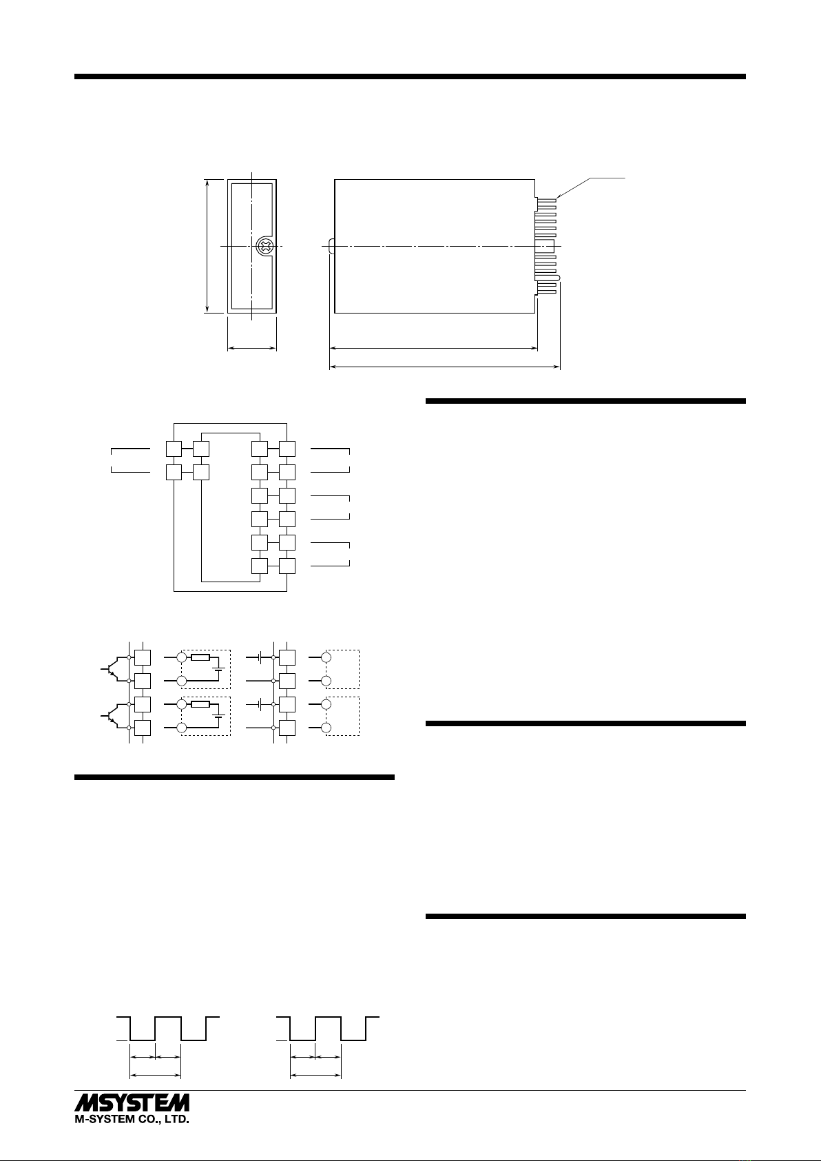
■EXTERNAL DIMENSIONS unit: mm (inch)
I/O PINS
17.5 (.69)
48 (1.89)
75 (2.95)
83 (3.27)
■CONNECTION DIAGRAM
+
–
Installation Base
OUTPUT 1
6
7
8
9
10
11
+
–
+
–
OUTPUT 2
1
2
A
B
POWER
+
–
INPUT
■Open Collector
Output Connection Examples
+
–
6
7
+
–
■Voltage Pulse
+
–
6
7
+
–
+
–
8
9
+
–
8
9
+
–
+
–
CHECKING
1) Terminal wiring: Check that all cables are correctly con-
nected according to the connection diagram.
2) Power input: Check the power input voltage.
3) Input: Check that the input signal is within 0 – 100% of
the full-scale.
4) Output: Check that the load meets the specifications as
described below:
• Open collector: 50V DC @ 50mA max. (load ≤ 1kΩ)
• 5V pulse: ≥ 1kΩ
The output pulse width is as illustrated below. Check
specifications of the receiving device.
•Open Collector •Voltage Pulse
OFF
ON
50
%
50
%
1 / f
50
%
50
%
1 / f
H Level
L Level
ADJUSTMENT PROCEDURE
This unit is calibrated at the factory to meet the ordered
specifications, therefore you usually do not need any cali-
bration.
For matching the signal to a receiving instrument or in case
of regular calibration, adjust the output as explained in the
following.
■HOW TO CALIBRATE THE OUTPUT SIGNAL
Use a signal source and measuring instruments of sufficient
accuracy level. Turn the power supply on and warm up for
more than 10 minutes.
(Output 1 and Output 2 are linked.)
1) ZERO: Apply 5% input and adjust output to 5%.
2) SPAN: Apply 100% input and adjust output to 100%.
3) Check ZERO adjustment again with 5% input.
4) When ZERO value is changed, repeat the above proce-
dure 1) – 3).
MAINTENANCE
Regular calibration procedure is explained below:
■CALIBRATION
Warm up the unit for at least 10 minutes. Apply 0%, 5%,
25%, 50%, 75% and 100% input signal. Check that the out-
put signal for the respective input signal remains within
accuracy described in the data sheet. When the output is
out of tolerance, recalibrate the unit according to the “AD-
JUSTMENT PROCEDURE” explained earlier.
LIGHTNING SURGE PROTECTION
M-System offers a series of lightning surge protector for
protection against induced lightning surges. Please contact
M-System to choose appropriate models.
M8AP
5-2-55, Minamitsumori, Nishinari-ku, Osaka 557-0063 JAPAN
Phone: +81(6)6659-8201 Fax: +81(6)6659-8510 E-mail: info@m-system.co.jp
EM-5485 Rev.3 P. 2 / 2