M-system JPR2 User manual

JPR2
P. 1 / 8EM-1580 Rev.2
PULSE SCALER
(eld-programmable; built-in excitation) MODEL JPR2
INSTRUCTION MANUAL
BEFORE USE ....
Thank you for choosing M-System. Before use, please check
contents of the package you received as outlined below.
If you have any problems or questions with the product,
please contact M-System’s Sales Office or representatives.
■ PACKAGE INCLUDES:
Signal conditioner (body + base socket) ...................... (1)
■ MODEL NO.
Confirm Model No. marking on the product to be exactly
what you ordered.
■ INSTRUCTION MANUAL
This manual describes necessary points of caution when
you use this product, including installation, connection and
basic maintenance procedures.
When you need to change software settings, please refer to
the Operation Manual for Model PU-2x (EM-9255), Section
B.
This unit is factory adjusted and calibrated according to the
Ordering Information included in the product package. If
you don’t need to change the pre-adjusted setting, you can
skip the sections on hardware setting and calibration in this
manual and the Operation Manual for Model PU-2x.
POINTS OF CAUTION
■ POWER INPUT RATING & OPERATIONAL RANGE
• Locate the power input rating marked on the product and
confirm its operational range as indicated below:
85 – 132V AC rating: 85 – 132V, 47 – 66 Hz, approx. 6VA
12V, 24V and 48V DC rating: Rating ±10%, approx. 3.3W
110V DC rating: 85 – 150V, approx. 3.3W
■ UNPLUGGING THE UNIT
• Before you remove the unit from its base socket or mount
it, turn off the power supply and input signal for safety.
■ ENVIRONMENT
• Indoor use
• When heavy dust or metal particles are present in the air,
install the unit inside proper housing with sufficient ven-
tilation.
• Do not install the unit where it is subjected to continuous
vibration. Do not subject the unit to physical impact.
• Environmental temperature must be within -5 to +60°C
(23 to 140°F) with relative humidity within 30 to 90% RH
in order to ensure adequate life span and operation.
■ WIRING
• Do not install cables (power supply, input and output)
close to noise sources (relay drive cable, high frequency
line, etc.).
• Do not bind these cables together with those in which
noises are present. Do not install them in the same duct.
■ AND ....
• The unit is designed to function as soon as power is sup-
plied, however, a warm up for 10 minutes is required for
satisfying complete performance described in the data
sheet.
COMPONENT IDENTIFICATION
■ HOW TO OPEN THE FRONT COVER
Position your finger on the hook at the top of front cover
and pull.
INSTALLATION
Detach the yellow clamps located at the top and bottom of
the unit to separate the body from the base socket.
■ DIN RAIL MOUNTING
Set the base socket so that its
DIN rail adaptor is at the bot-
tom. Position the upper hook
at the rear side of base socket
on the DIN rail and push in
the lower. When removing
the socket, push down the
DIN rail adaptor utilizing a
minus screwdriver and pull.
■ WALL MOUNTING
Refer to the drawings in the
following page.
Body Base Socket
Connection Diagram
Front Cover
Specifications
The shape of base socket may be different
for some models.
Clamp
(top & bottom)
DIN Rail
35mm wide
Spring Loaded
DIN Rail Adaptor
Shape and size of the base socket
are slightly different with various
socket types.

JPR2
P. 2 / 8EM-1580 Rev.2
TERMINAL CONNECTIONS
Connect the unit as in the diagram below or refer to the connection diagram on top of the unit.
■ EXTERNAL DIMENSIONS unit: mm (inch)
■ CONNECTION DIAGRAM
3456
2187
80 (3.15)
50 (1.97) 107 (4.21)
127 (5) [3.3 (.13)]
80 (3.15)
20
(.79)
35.4 (1.39)
40 (1.57)
50 (1.97)
7.8 (.31)
CLAMP
(top & bottom)
DIN RAIL
35mm wide
2–4.5 (.18) dia.
MTG HOLE
15 (.59) deep
8–M3.5
SCREW
• When mounting, no extra space is needed between units.
3
5
4
+
5kΩ
100Ω
100Ω
n Open Collector or
Mechanical Contact
Input Connection Examples
+
–
–Vsns
PWR
n 2-Wire Current Pulse
• Built-in Excitation
3
5
4
–
+
Vsns
2-WIRE
PICK-UP
• External DC Supply
3
5
4
–
Vsns
2-WIRE
PICK-UP +
+
DC SUPPLY
–
n Voltage Pulse
3
5
4
+
+
–
–Vsns
PWR
n RS-422 Line Driver Pulse
+
+
–
–
Vsns
PWR
n Open Collector
Output Connection Examples
+
–
1
2
+
–
n Voltage Pulse
+
–
1
2
+
–
n Noncontact AC/DC Switch
• AC Powered
1
n RS-422 Line Driver Pulse
2LOAD
Relay or
Counter Coil
Varistor or Spark
Quenching Circuit
• DC Powered
1
2LOAD
Relay or
Counter Coil
Spark Quenching
Diode
6
+
–
3
5
4+
–
2
+
–
+
–
1
n OPEN COLLECTOR, MECHANICAL CONTACT,
VOLTAGE PULSE or 2-WIRE CURRENT PULSE INPUT
n RS-422 LINE DRIVER INPUT
PU-2x
MODULAR JACK
PU-2x
MODULAR JACK
+
–
INPUT
3
5
4
+
SENSOR EXCITATION
4
+
–
INPUT
+
–
3
5
6
SENSOR EXCITATION
+
–
OUTPUT
1
2
U(+)
V(–)
POWER
7
8
+
–
OUTPUT
1
2
U(+)
V(–)
POWER
7
8
With 24V excitation and open collector/mechanical contact input,
the voltage across the terminals 3 – 4, divided in the waveform shaper,
is of approx. 16V.

JPR2
P. 3 / 8EM-1580 Rev.2
EXPLANATIONS OF TERMS & FUNCTIONS
■ SCALING FACTOR, INPUT PULSE SET COUNT & OUT-
PUT PULSE SET COUNT
The scaling factor, rate of number of output pulses divided
by number of input pulses, is determined by two param-
eters: input pulse set count and output pulse set count.
The JPR2 output is designed to be proportional in number
of pulses relative to the input. For example, when the pulse
rate is set to 0.0583, the JPR2, provided with 10000 input
pulses, outputs 583 pulses. However, the output is not sup-
plied in a constant frequency. The JPR2 counts the number
of input pulses during the sampling time (period) and stores
it in the internal buffer counter, and provides the number
of output pulses multiplied by the scaling factor for the
number of input pulses, by the end of next sampling cycle.
With the maximum output frequency limit, those pulses ex-
ceeding the limit are still in the buffer and output only in
the following cycle.
■ SAMPLING TIME
The sampling time is defined as a time period required by
the JPR2 to count the input signals for one cycle. With its
factory default setting (0.1 sec.), the output is refreshed
every 100 milliseconds.
This setting is not usually be changed unless for a specific
purpose.
■ MAXIMUM OUTPUT FREQUENCY LIMIT
You can limit the maximum output frequency from the
JPR2.
The JPR2 multiplies the number of input pulses by the scal-
ing factor. However when the output pulses are supplied to
a low-speed response counter, the number of output pulses
(output frequency of the JPR2) may have to be limited with-
in a certain level.
Those surplus pulses remains in the buffer and are output
in the following sampling cycles within the limit.
■ OPERATION
[Example]
Input frequency: 2 Hz
Sampling time: 0.5 sec.
Pulse rate: 3/2
Output pulse width: Duty ratio approx. 50%
Max. output frequency: 1 kHz
1) The JPR2 counts the number of pulses during the sam-
pling time (period). In the example, 1 count in 0.5 sec.
time.
2) Converts the number in the preset rate. In the example,
1 pulse ×3/2 = 1.5 pulses
3) Outputs the converted pulses in the next sampling pe-
riod. If certain pulses are not output within the time due
to a fraction or the max. output frequency limit, they are
output in the following sampling period. In the example,
1 pulse is output in the second period, two pulses are
output in the third to adjust the fraction.

JPR2
P. 4 / 8EM-1580 Rev.2
OUTPUT LOGIC
H
L
Voltage Pulse
or
RS-422
Line Driver Pulse
OUTPUT WAVEFORM
Open collector
or
Noncontact
AC/DC Switch
The pulse width in one-shot means the bold lined section of a pulse waveform.
No pulse width conversion
One-shot, detecting input pulse rise
Non
Inverted
Voltage Pulse
2-wire Current Pulse
RS-422 Line Driver Pulse
Open Collector or
Noncontact AC/DC Switch
INPUT WAVEFORM
H
H
L
H
H
L
L
H
L
OFF
ON
L
L
H
One-shot, detecting input pulse drop
H
L
No pulse width conversion
One-shot, detecting input pulse rise
Inverted
H
H
L
H
H
L
L
L
L
H
One-shot, detecting input pulse drop
OFF
ON
No pulse width conversion
One-shot, detecting input pulse rise
Non
Inverted
OFF
ON
OFF
ON
OFF
ON
OFF
ON
OFF
ON
OFF
ON
OFF
ON
OFF
ON
OFF
ON
OFF
ON
OFF
ON
One-shot, detecting input pulse drop
No pulse width conversion
One-shot, detecting input pulse rise
Inverted
One-shot, detecting input pulse drop

JPR2
P. 5 / 8EM-1580 Rev.2
HARDWARE SETTING & CALIBRATION
5
4
3
2
1
0
9
8
7
6
1
2
3
4
5
6
7
8
1
2
3
4
5
6
7
8
1
2
3
4
5
6
7
8
ON
SW1
SW3
SW2
Unused
Detecting Level Adj.
Detecting Level Adj. Pin
Pulse Amplitude Selector
Input Type Selectors
Unused
Sensor Excitation Adj.
Modular Jack
Input Monitor LED
■ PULSE AMPLITUDE (rotary switch) (*) Factory setting
For RS-422 line driver pulse, this setting is invalid.
For voltage pulse input, select the pulse amplitude (V p-p)
among the switch positions 0 through 6. For open collector,
mechanical contact or two-wire current pulse input, set the
switch to 7. DO NOT SET to 8 or 9. The power supply to the
unit must be turned off when changing the setting.
SW PULSEAMPLITUDE MAX.INPUTVOLTAGE
0 50 – 100V p-p 50V
1 25 – 50V p-p 50V
2 10 – 25V p-p 25V
3 5 – 10V p-p 10V
4 1 – 5V p-p 5V
5 0.5 – 1V p-p 1V
6*10.1 – 0.5V p-p 0.5V
7(*) Open collector, mechanical contact or two-wire
current pulse
*1. Maximum frequency limited to 50 kHz.
■ DIP SWITCH SETTING (*) Factory setting
For RS-422 line driver pulse, the noise filter setting is
invalid.
SW2 is not used. Turn all switches to OFF.
The power supply to the unit must be turned off when
changing the setting.
• Input Type
• Noise Filter
‘High’ setting is used for the input frequency ≤10 Hz.
‘Low’ setting is used for the input frequency ≤500 Hz.
For mechanical contact input, ‘High’ setting is recommend-
ed to prevent typical chattering from counting.
■ CAUTION FOR RS-422 LINE DRIVER PULSE
For RS-422 line driver pulse, the input amplitude, detect-
ing level and noise filter settings are all invalid. However,
in order to prevent errors in setting, set these switches as
follows:
Input amplitude = 50 – 100 Vp-p (SW=0)
Detecting level = 0V
Noise filter = None
INPUTTYPE SW1
1 2 3 4 5 6
Open collector (*) ON OFF ON OFF OFF ON
Mechanical contact
Voltage pulse OFF OFF ON OFF OFF OFF
2-wire current OFF ON ON OFF OFF ON
RS-422 line driver OFF OFF OFF ON ON OFF
NOISEFILTER SW1-7 SW1-8
High ON OFF
Low (*) OFF ON
None OFF OFF
n EXAMPLE 1: VOLTAGE PULSE with Amplitude 5V p-p, DC Offset 2.5V, Input Frequency 1 kHz
Input type: Voltage
Input amplitude: 1 – 5V p-p
Detecting level:
2.5V (DC Offset ×Sensitivity Scale = 2.5 ×1/1 = 2.5V)
(Set to the offset value after it is scaled by the sensitiv-
ity scale.)
Noise filter: None
The rotary switch and DIP switch are configured as shown to the
right.
n EXAMPLE 2: VOLTAGE PULSE with Amplitude 30V p-p, DC Offset 15V, Input Frequency 50 Hz
Input type: Voltage
Input amplitude: 25 – 50V p-p
Detecting level:
1.5V (DC Offset ×Sensitivity Scale = 15 ×1/10 = 1.5V)
(Set to the offset value after it is scaled by the sensitiv-
ity scale.)
Noise filter: Low
The rotary switch and DIP switch are configured as shown to the
right.
ON
12345678
ON
12345678
SW3 SW1 SW2
Not Used (All OFF)
5
6
7
8
9
0
1
2
3
4
SW3
ON
12345678
ON
12345678
SW1 SW2
5
6
7
8
9
0
1
2
3
4
Not Used (All OFF)

JPR2
P. 6 / 8EM-1580 Rev.2
■ DETECTING LEVEL
Determine the appropriate detecting level referring to the flow chart below.
A specific sensitivity scale is applied according to the pulse
amplitude setting. The scaled input voltage is then com-
pared to the detecting voltage level (0 – 5V).
The scaled H level voltage must be equal to or higher than
the detecting level so that the pulse state is accurately de-
tected. (Refer to the instruction manual for detailed infor-
mation about adjusting the detecting level.)
Table1
SW PULSEAMPLITUDE SENSITIVITYSCALE
0 50 – 100V p-p 1/20
1 25 – 50V p-p 1/10
2 10 – 25V p-p 1/5
3 5 – 10V p-p 1/2
4 1 – 5V p-p 1
5 0.5 – 1V p-p 5
6 0.1 – 0.5V p-p 10
Open collector
7 Mechanical contact 1
Two-wire current pulse
START
Confirm the Sensitivity Scale in Table 1
below.
Assign the value in the following equation.
Detecting Level (V)*1=
DC Offset (V)*2×Sensitivity Scale
Adjust the detecting level to the value
calculated above following the procedure
explained below.
Adjust the detecting level
appropriate for the sensor
excitation voltage.
Adjust the detecting level
to 0V appropriate for RS-
422 line driver pulse input.
Voltage pulse input or
2-wire current pulse input? No
No
Yes
Open collector input?
Yes
*1. Rounded off to one decimal place.
*2. Divide a current input (mA) by 10 and
convert it into voltage (V).
Excitation
≥10V DC
7 – 10V DC
5 – 7V DC
Detect. Level
2V
1.5V
1V
• Setting Examples
Voltage Input (DC Offset = Pulse Amplitude / 2)
PULSE AMPLITUDE DETECTING
AMPLITUDE(Vp-p) RANGE(Vp-p) LEVEL(V)
50 50 – 100 1.3
50 25 – 50 2.5
30 25 – 50 1.5
25 10 – 25 2.5
15 10 – 25 1.5
10 5 – 10 2.5
7.5 5 – 10 1.9
5 1 – 5 2.5
3.5 1 – 5 1.8
2 1 – 5 1
1 0.5 – 1 2.5
0.5 0.1 – 0.5 2.5
Current Input (DC Offset = Pulse Amplitude / 2)
PULSE AMPLITUDE DETECTING
AMPLITUDE(mAp-p) RANGE LEVEL(V)
15 (1.5Vp-p) Set to open collector, 0.8
25 (2.5Vp-p)
mechanical contact or
1.3
two-wire current pulse
Set DC offset to 0V for 100Vp-p pulse input.

JPR2
P. 7 / 8EM-1580 Rev.2
• How to Change the Detecting Level
A voltmeter of class 0.5 or better accuracy with pointed
probes is required.
1) Connect the negative probe of voltmeter to the terminal
4 of base socket.
2) If you need a noise filter, set the SW1-7 and SW1-8 in
advance.
3) Connect the positive probe to the test pin and turn the
Detecting Level Adjustment until the meter shows de-
sired value.
4) Apply input signals and check that input monitor LED
(PL1) flashes according to the input signal.
If the LED does not flash, the detecting level may be out
of pulse amplitude range. Check the pulse amplitude and
the DC offset again and readjust the detecting level.
■ SENSOR EXCITATION ADJUSTMENT
You can change the sensor excitation voltage with the
sensor excitation adj. located behind the front cover. If you
need to change it, check that the required current is within
the specification.
• How to Change the Excitation
A voltmeter and ammeter of class 0.5 or better accuracy
are required.
1) Connect the voltmeter across the terminals 5 – 4.
2) Connect the ammeter to terminal 5.
3) Turn the potentiometer until the meter shows the de-
sired value.
Check that the current value indicated on the ammeter
is within the allowable limit. If the value is greater than
the limit, lower the voltage value or connect a separate
power source. Otherwise, the transmitter may fail.
5
4
3
2
1
0
9
8
7
6
1
2
3
4
5
6
7
8
1
2
3
4
5
6
7
8
SW1
SW3
SW2
Detecting Level Adj.
Detecting Level Adj. Pin
Input Monitor LED
V
–
Connect to Terminal 4
of the base socket.
Voltmeter
PU-2x
MODULAR JACK
–
5
4
+
+
–
OUTPUT
1
2
U(+)
V(–)
POWER
7
8
SENSOR EXC. V
A
Ammeter
Voltmeter
25
5
12
24
60 120
CURRENT (mA)
VOLTAGE (V)
Voltage (V) ×Current (A) ≤600mW

JPR2
P. 8 / 8EM-1580 Rev.2
M-SYSTEM WARRANTY
M-SystemwarrantssuchnewM-Systemproductwhichitmanufacturestobefreefromdefectsinmaterialsandworkmanshipduringthe36-monthperiodfollowingthedatethatsuch
productwasoriginallypurchasedifsuchproducthasbeenusedundernormaloperatingconditionsandproperlymaintained,M-System’ssoleliability,andpurchaser’sexclusive
remedies,underthiswarrantyare,atM-System’soption,therepair,replacementorrefundofthepurchasepriceofanyM-Systemproductwhichisdefectiveunderthetermsofthis
warranty.Tosubmitaclaimunderthiswarranty,thepurchasermustreturn,atitsexpense,thedefectiveM-Systemproducttothebelowaddresstogetherwithacopyofitsoriginal
salesinvoice.
THISISTHEONLYWARRANTYAPPLICABLETOM-SYSTEMPRODUCTANDISINLIEUOFALLOTHERWARRANTIES,EXPRESSORIMPLIED,INCLUDINGANYIMPLIED
WARRANTIESOFMERCHANTABILITYORFITNESSFORAPARTICULARPURPOSE.M-SYSTEMSHALLHAVENOLIABILITYFORCONSEQUENTIAL,INCIDENTALOR
SPECIALDAMAGESOFANYKINDWHATSOEVER.
M-SystemCo.,Ltd.,5-2-55,Minamitsumori,Nishinari-ku,Osaka557-0063JAPAN,Phone:(06)6659-8201,Fax:(06)6659-8510,E-mail:[email protected]
SOFTWARE SETTING
Please refer to the Operation Manual for Model PU-2x (EM-9255), Section B: (B-1) Introduction, (B-2) General Operation
Description, (B-3) Operation Flowchart for general information.
CHECKING
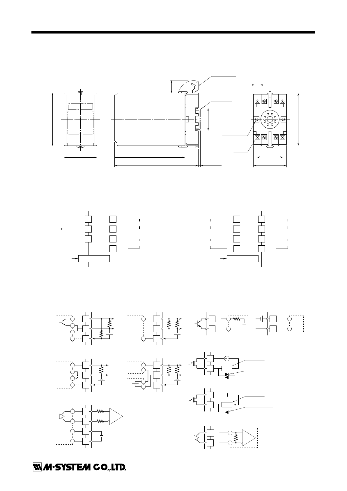
1) Terminal wiring: Check that all cables are correctly con-
nected according to the connection diagram.
2) Power input voltage: Check voltage across the terminal
7 – 8 with a multimeter.
3) Check the input signal.
4) Check the output signal.
[GROUP01]
ITEM
MDF.
INPUTDATA EXAMPLE(EXAMPLE) DEFAULT CONTENTS
CODE
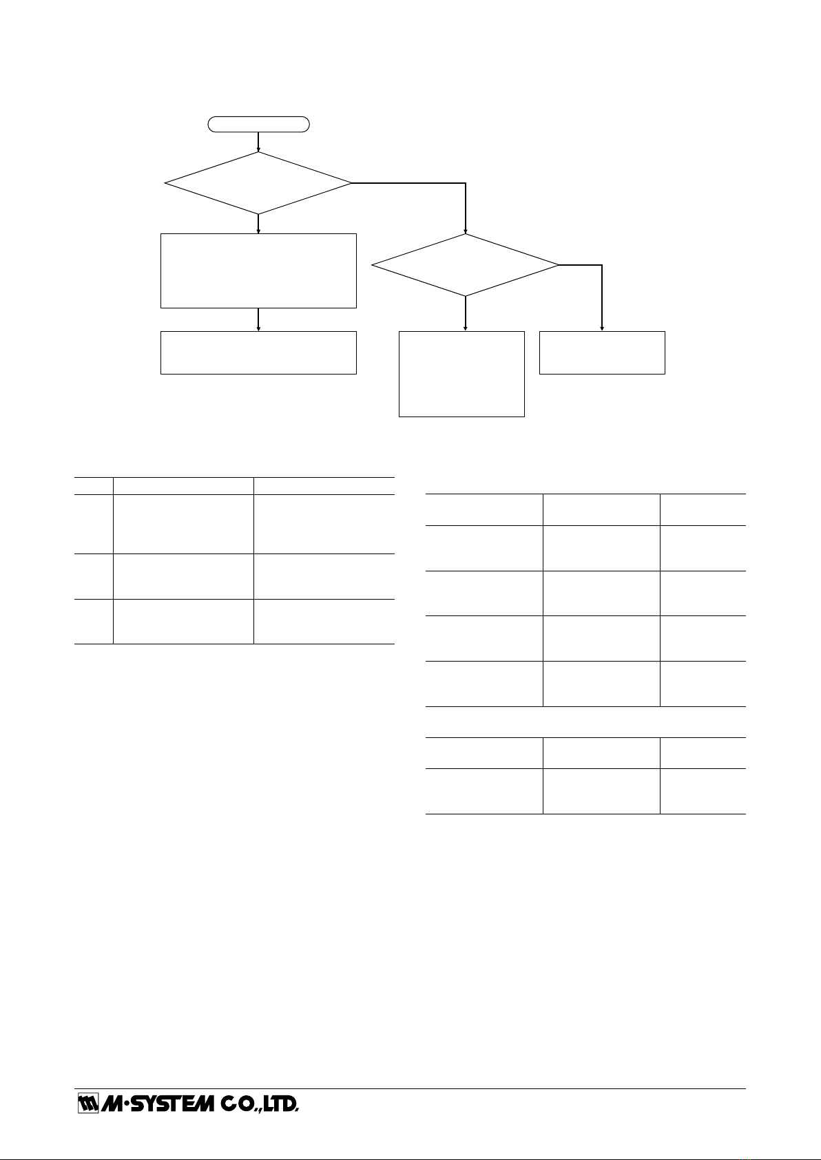
01 S N/A MAINTENANCE SWITCH
0 MTSW : MON.MODE 0 : Data indication only.
1 MTSW : PRG.MODE 1 : All ‘P’ marked parameters are modifiable.
02 P Alphanumeric TG : XXXXXXXXXX N/A Tag name entry (10 characters max.)
03 P Numeric CNT : XXXXXX 0 Total input pulses (any count selectable)
04 P Numeric IN : XXXXXX 1 Input pulse set count (1 to 1 000 000)
05 P Numeric OUT : XXXXXX 1 Output pulse set count (1 to 1 000 000)
06 P Numeric (Hz) FRQ : XXXX.XHz 10.0 Max. output frequency limit (0.5 to 100000.0 Hz)
07 P Numeric (s) SMP : X.XXs 0.10 Sampling time (0.01 to 100.00 s)
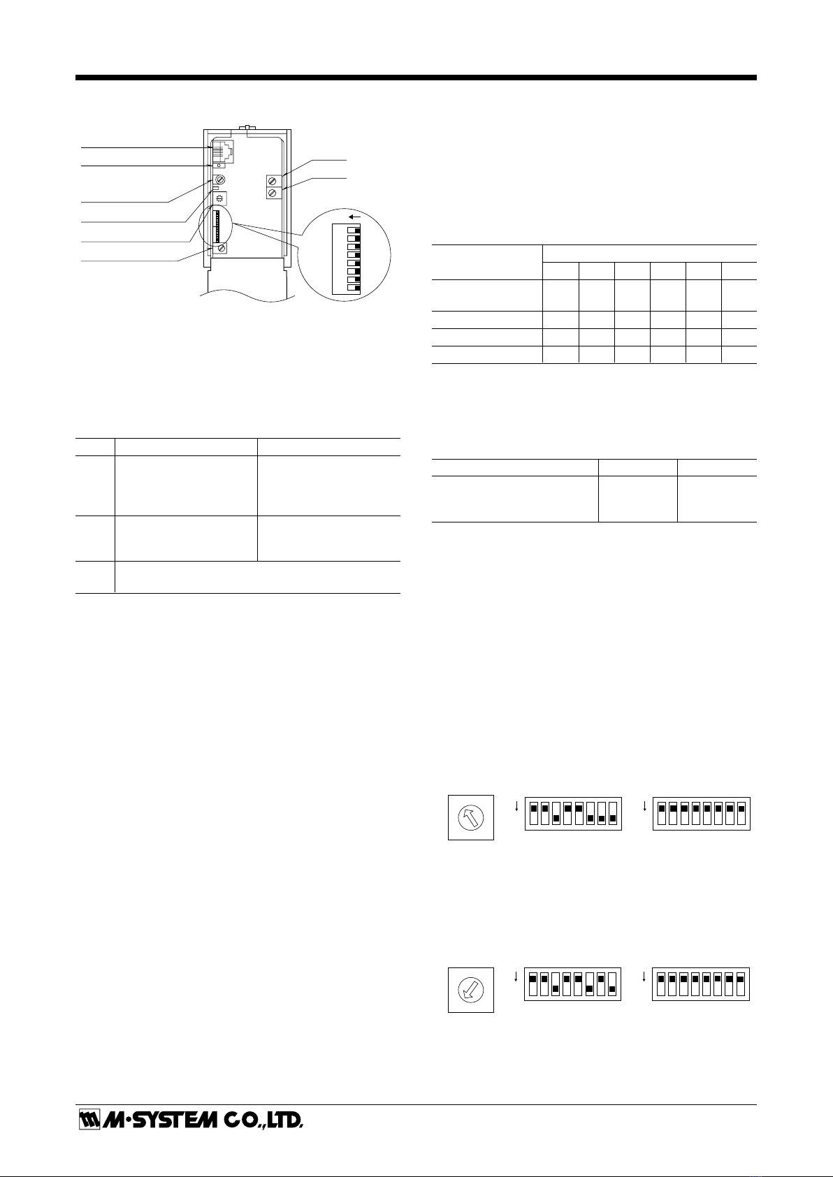
08 D No input N/A
Input specification selected with the front rotary switch
SW : IN_V 1/20 SW = 0, Voltage input, Sensitivity scale = 1/20
SW : IN_V 1/10 SW = 1, Voltage input, Sensitivity scale = 1/10
SW : IN_V 1/5 SW = 2, Voltage input, Sensitivity scale = 1/5
SW : IN_V 1/2 SW = 3, Voltage input, Sensitivity scale = 1/2
SW : IN_V 1/1 SW = 4, Voltage input, Sensitivity scale = 1/1
SW : IN_V 5/1 SW = 5, Voltage input, Sensitivity scale = 5/1
SW : IN_V 10/1 SW = 6, Voltage input, Sensitivity scale = 10/1
SW : IN_OC, mA SW = 7, Open collector, mechanical contact or two-wire
current input
SW : no use SW = 8, (not used)
SW : no use SW = 9, (not used)
SW : IN_RS422 DIP switch set to RS-422 line driver pulse
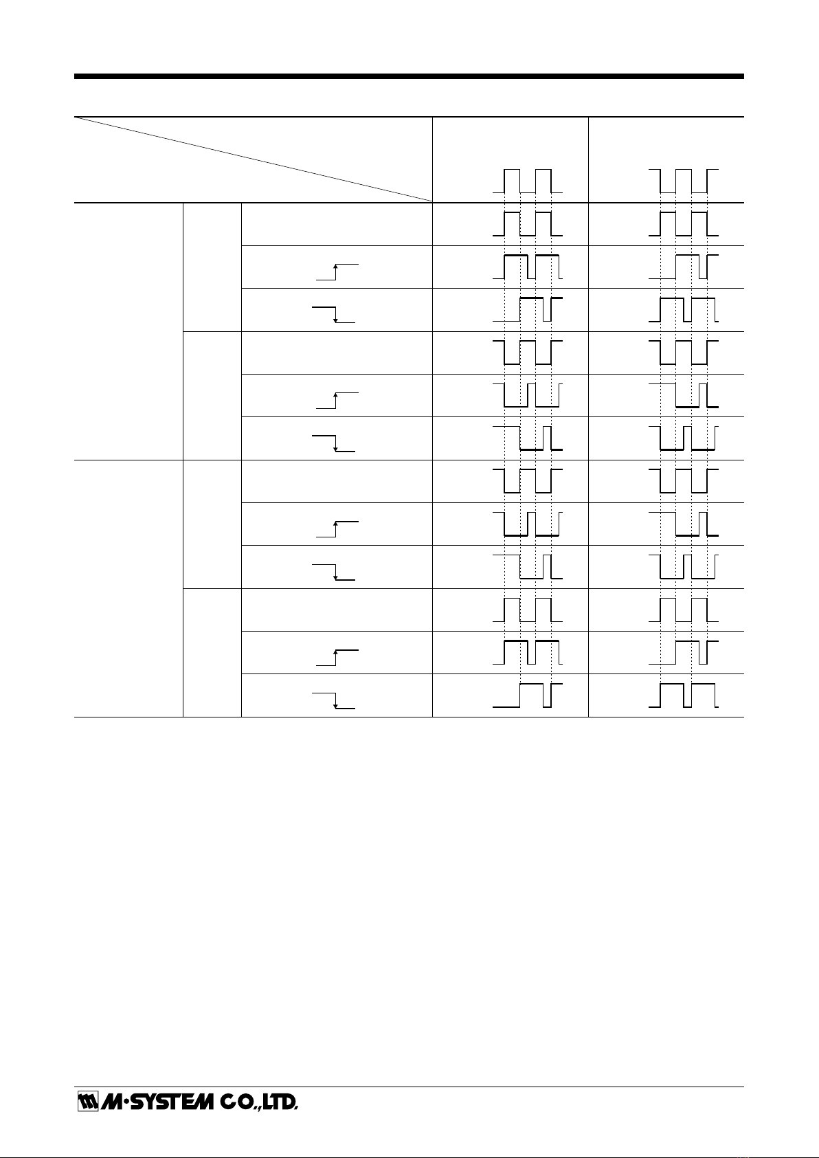
09 P * Count mode
*Factory default depends upon other specifications.
0 IN_EDGE : 0 Count at pulse rise
1 IN_EDGE : 1 Count at pulse sink
Modication Code
D: No modification (writing) possible. Used only for monitoring (reading).
S: Modifiable at any time.
P: Modifiable only when the MAINTENANCE SWITCH is in the ‘PRG’ mode.
ROM Version Indication
[GROUP 00] [ITEM 99]
Table of contents
Other M-system Media Converter manuals

M-system
M-system 15RS User manual

M-system
M-system M8BS-8E1A User manual

M-system
M-system M8MS User manual

M-system
M-system KDA3 User manual

M-system
M-system M80MS User manual

M-system
M-system M8TS User manual

M-system
M-system 10AP User manual

M-system
M-system 17TG User manual

M-system
M-system 18AC User manual

M-system
M-system JAPD2 User manual

M-system
M-system M8XM2 User manual

M-system
M-system JFR2 User manual

M-system
M-system M8RS User manual

M-system
M-system M8AP User manual

M-system
M-system WRPP User manual

M-system
M-system 18JM User manual

M-system
M-system 18TG User manual

M-system
M-system JPR2 User manual

M-system
M-system M8XR2 User manual

M-system
M-system M8BS-8U0-R User manual