manuals.online logo
Brands
  1. Home
  2. •
  3. Brands
  4. •
  5. M-system
  6. •
  7. Media Converter
  8. •
  9. M-system M8XR2 User manual

M-system M8XR2 User manual

5-2-55, Minamitsumori, Nishinari-ku, Osaka 557-0063 JAPAN
Phone: +81(6)6659-8201 Fax: +81(6)6659-8510 E-mail: info@m-system.co.jp
EM-5471 Rev.4 P. 1 / 4
INSTRUCTION MANUAL
BEFORE USE ....
Thank you for choosing M-System. Before use, please check
contents of the package you received as outlined below.
If you have any problems or questions with the product,
please contact M-System’s Sales Office or representatives.
■PACKAGE INCLUDES:
Signal conditioner ...............................................................(1)
■MODEL NO.
Confirm Model No. marking on the product to be exactly
what you ordered.
■INSTRUCTION MANUAL
This manual describes necessary points of caution when
you use this product, including installation, connection and
basic maintenance procedures.
The unit is programmable using the PC Configurator Soft-
ware. For detailed information on the PC configuration,
refer to the JXCON users manual. The JXCON PC Con-
figurator Software is downloadable at M-System’s web site:
http://www.m-system.co.jp.
POINTS OF CAUTION
■POWER INPUT RATING & OPERATIONAL RANGE
• Locate the power input rating marked on the product and
confirm its operational range as indicated below:
24V DC rating: 24V ±10%, approx. 50mA
(70mA for current output)
■GENERAL PRECAUTIONS
• Before you remove the unit or mount it, turn off the power
supply and input signal for safety.
■ENVIRONMENT
• Indoor use.
• When heavy dust or metal particles are present in the
air, install the unit inside proper housing with sufficient
ventilation.
• Do not install the unit where it is subjected to continuous
vibration. Do not subject the unit to physical impact.
• Environmental temperature must be within 0 to 55°C (32
to 131°F) with relative humidity within 30 to 95% RH in
order to ensure adequate life span and operation.
• Be sure that the ventilation slits are not covered with ca-
bles, etc.
■WIRING
• Do not install cables close to noise sources (relay drive
cable, high frequency line, etc.).
• Do not bind these cables together with those in which
noises are present. Do not install them in the same duct.
■AND ....
• The unit is designed to function as soon as power is sup-
plied, however, a warm up for 10 minutes is required for
satisfying complete performance described in the data
sheet.
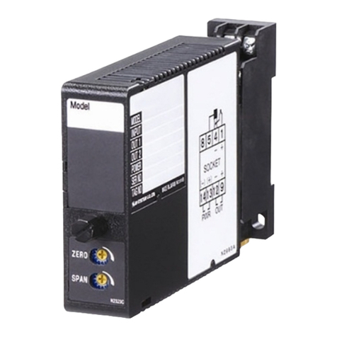
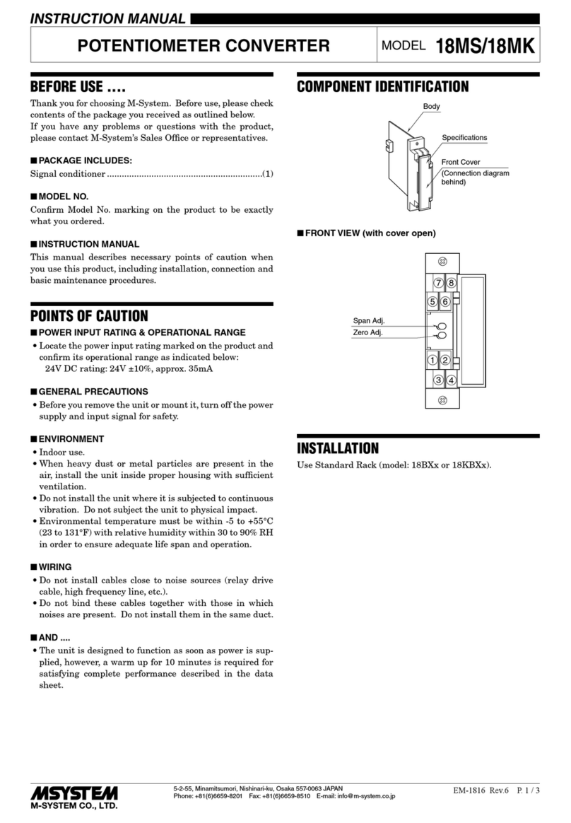
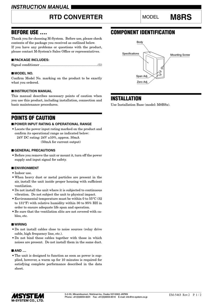
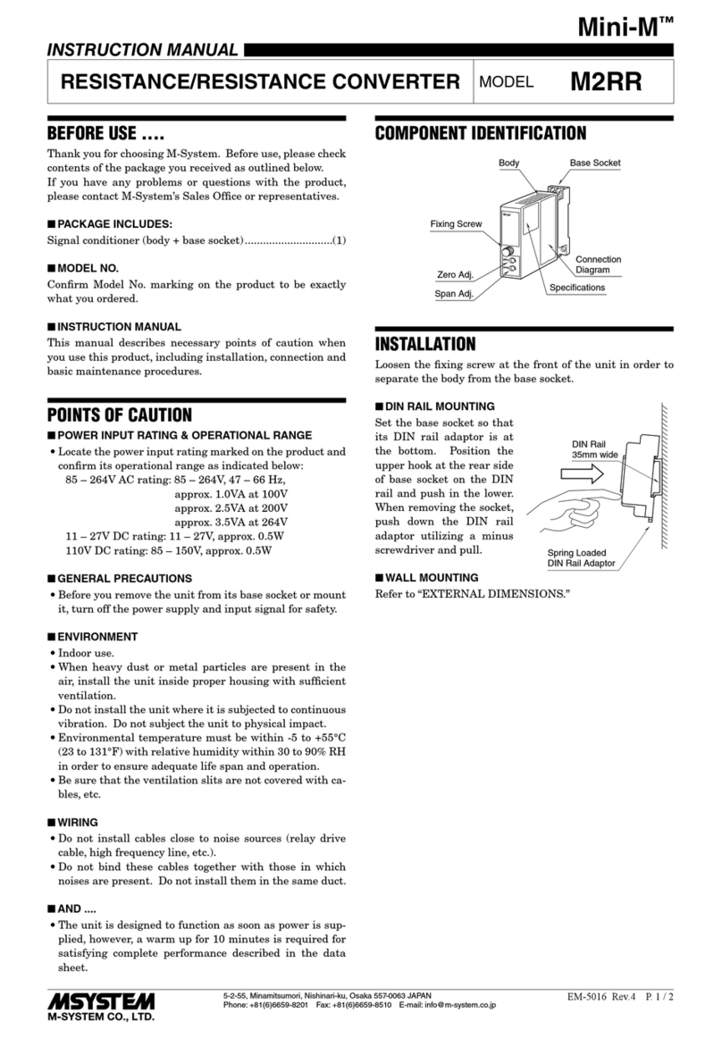
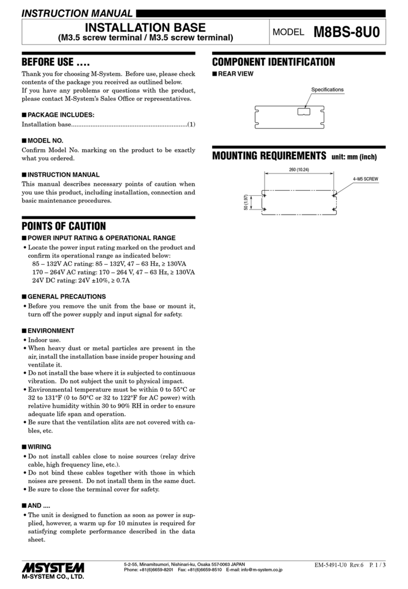
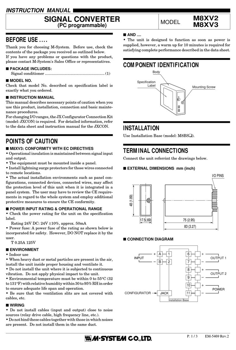
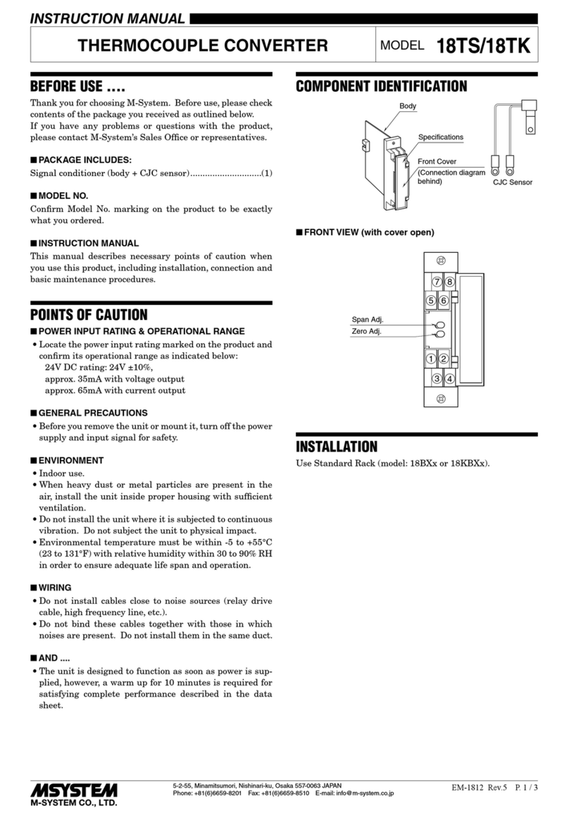
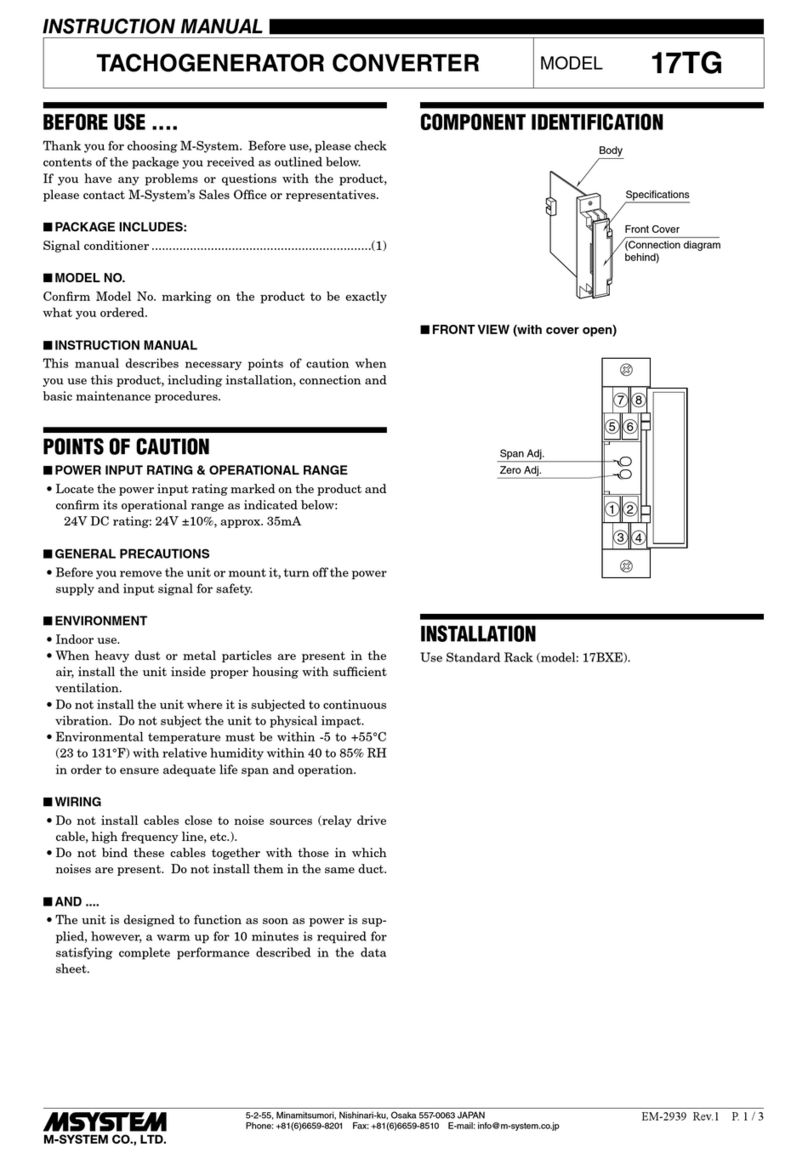
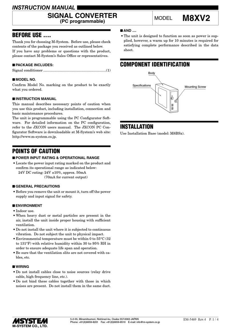
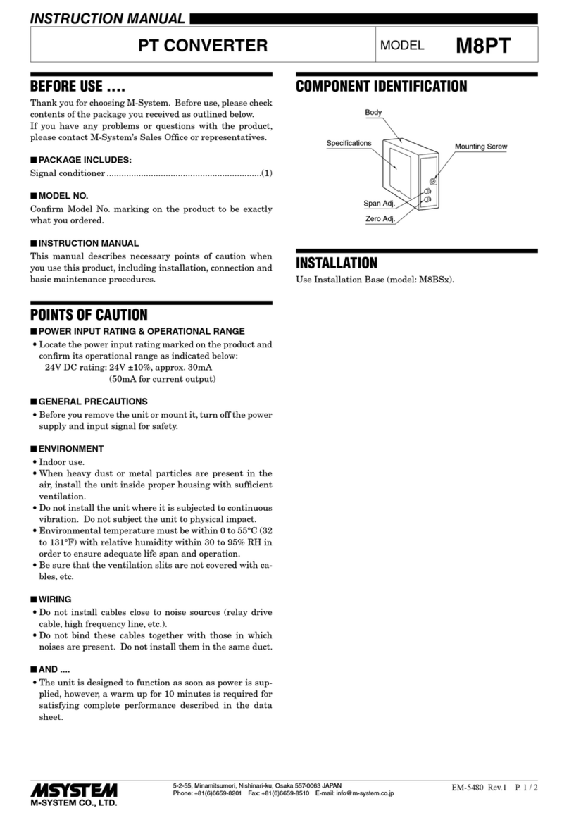
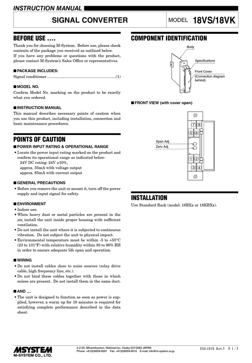
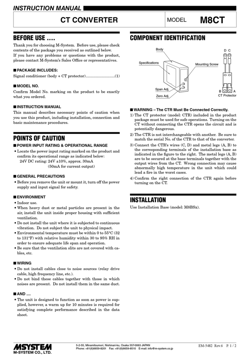
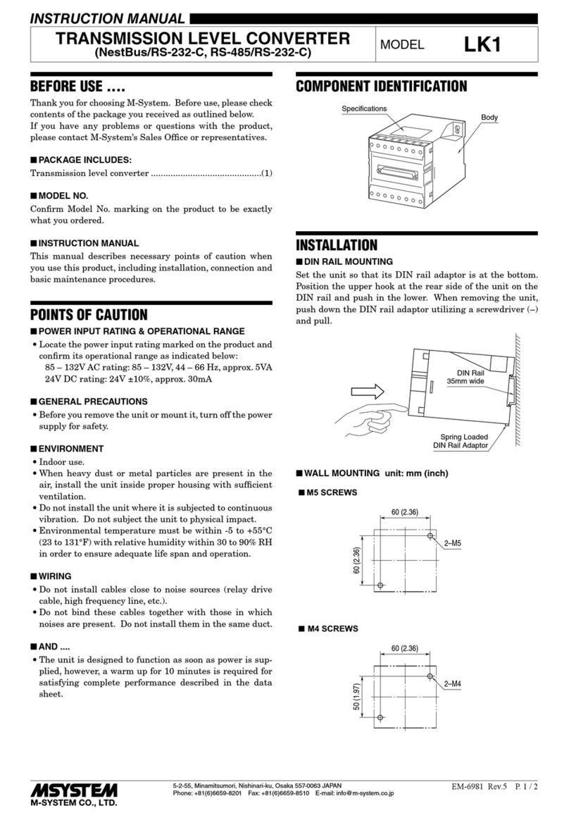
COMPONENT IDENTIFICATION
Specifications Mounting Screw
Body
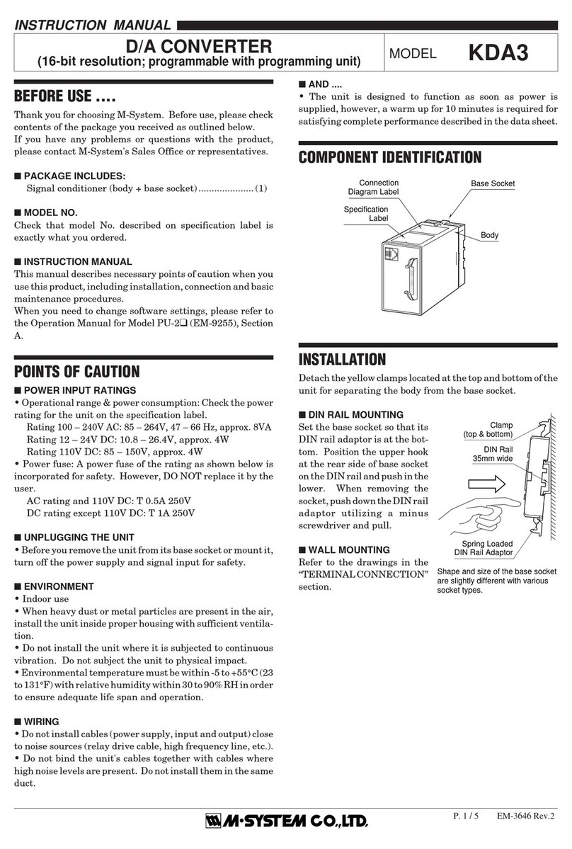
INSTALLATION
Use Installation Base (model: M8BSx).
RTD CONVERTER
(PC programmable) MODEL M8XR2
M8XR2
5-2-55, Minamitsumori, Nishinari-ku, Osaka 557-0063 JAPAN
Phone: +81(6)6659-8201 Fax: +81(6)6659-8510 E-mail: info@m-system.co.jp
EM-5471 Rev.4 P. 2 / 4
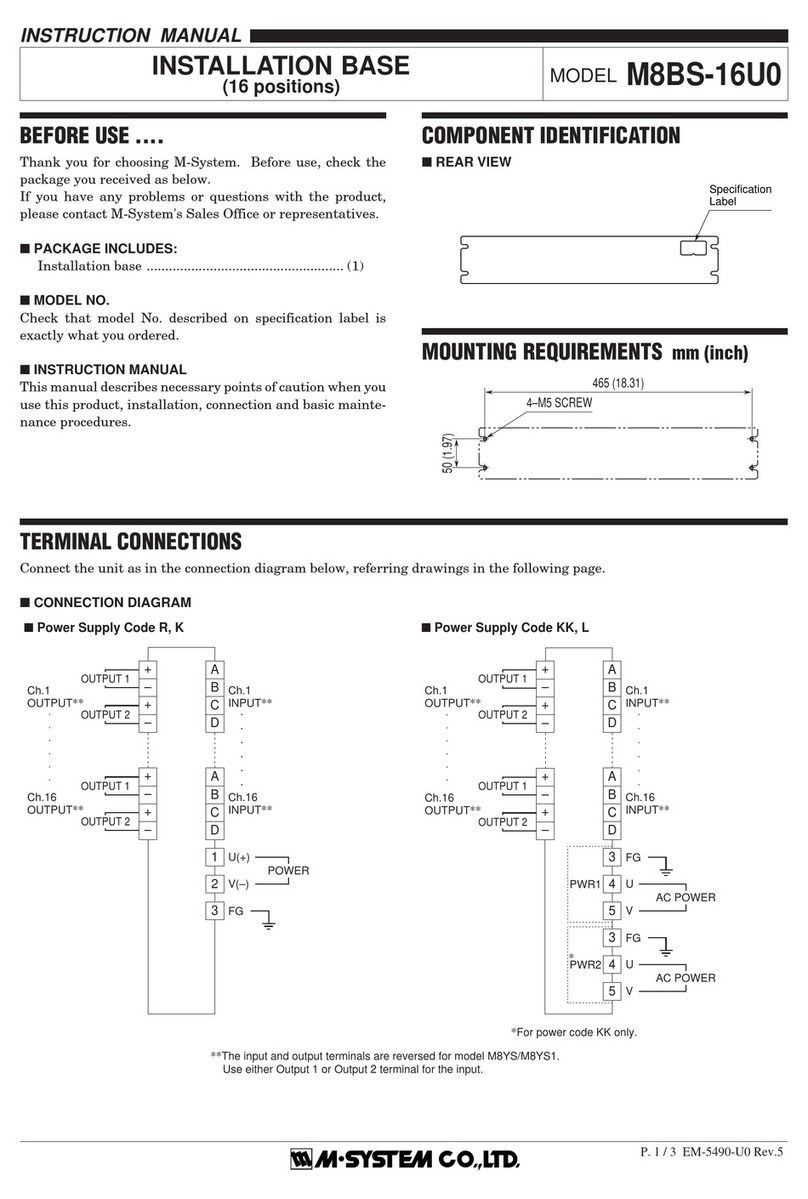
TERMINAL CONNECTIONS
Connect the unit as in the diagram below.
■EXTERNAL DIMENSIONS unit: mm (inch)
I/O PINS
17.5 (.69)
48 (1.89)
75 (2.95)
83 (3.27)
■CONNECTION DIAGRAM
+
–
Installation Base
OUTPUT 1
6
7
8
9
10
11
+
–
+
–
OUTPUT 2
1
POWER
CONFIGURATOR JACK
2
4
A
B
C
A
B
B
RTD
CHECKING
1) Terminal wiring: Check that all cables are correctly con-
nected according to the connection diagram.
2) DIP switches: Check the output range selector setting.
3) Power input: Check the power input voltage.
4) Input: Check voltage across the terminal A – B with a
sensitive voltmeter (With 20°C or 68°F, approx. 110mV
with Pt 100, approx. 55mV with Pt 50 Ω).
If RTD wires are broken, the output goes over 100% (be-
low 0% with downscale) due to burnout function. Con-
firm the status indicator LED pattern and check lead-
wires in such a case.
5) Output: Check that the load resistance meets the de-
scribed specifications.
6) Status indicator LED: Check that it blinks in a regular
pattern.
M8XR2
5-2-55, Minamitsumori, Nishinari-ku, Osaka 557-0063 JAPAN
Phone: +81(6)6659-8201 Fax: +81(6)6659-8510 E-mail: info@m-system.co.jp
EM-5471 Rev.4 P. 3 / 4
CALIBRATION
This unit is calibrated at the factory to meet the ordered
specifications, therefore you usually do not need any cali-
bration.
For matching the signal to a receiving instrument or in case
of regular calibration, adjust the output as explained in the
following.
■ZERO/SPAN & UP/DOWN SWITCHES
Fine zero and span adjustments can be done with the ZERO/
SPAN Selector and UP/DOWN switches. Calibrated values
are stored in the non-volatile memory, which will not be lost
even when you turn off power supply to the unit.
The output 1 and output 2 can be independently adjustable.
Zero and span are respectively set to 0% and 100% at the
factory, and field calibration can be reset to ex-factory set-
ting if necessary.
Adjustable range: ±5%
Zero/Span Selector
ZERO: UP/DOWN switches usable for zero adjustment.
OFF: UP/DOWN switches unavailable.
SPAN: UP/DOWN switches usable for span adjustment.
UP/DOWN Switches
UP: Pressing UP increases adjusted values.
DOWN: Pressing DOWN decreases adjusted values.
■FRONT VIEW
UP Switch
Status Indicator LED
Configurator Jack
DOWN Switch
■BOTTOM VIEW
Zero/Span Selector
SZ
OFF
Z
S
Zero/Span Selector
MODE SW POSITION
SPAN S
OFF ■
ZERO Z
■HOW TO CALIBRATE THE ZERO & SPAN
Use a signal source and measuring instruments of sufficient
accuracy level. Turn the power supply on and warm up for
more than 10 minutes.
The output 1 and output 2 adjustments are linked except
for (2) and (6).
1) Apply 0% input.
2) Select the Output 1 Zero: Slide the Zero/Span Selector to
the position Z.
Select the Output 2 Zero: Slide the Zero/Span Selector to
the position Z while pressing UP switch.
3) Press UP or DOWN switch and adjust the output to 0%.
Incrementing speed will be doubled when you keep press-
ing a switch.
4) Put the Zero/Span Selector back to the position OFF.
5) Apply 100% input.
6) Select the Output 1 Span: Slide the Zero/Span Selector to
the position S.
Select the Output 2 Span: Slide the Zero/Span Selector to
the position S while pressing UP switch.
7) Press UP or DOWN switch and adjust the output to
100%. Incrementing speed will be doubled when you
keep pressing a switch.
8) Put the Zero/Span Selector back to the position OFF.
9) Check Zero and Span adjustments again with 0% and
100% input respectively.
10) If the output value is changed, repeat the above proce-
dure (1) – (9).
■HOW TO RESET
After you calibrated manually with these switches, you
can reset them to its ex-factory state by pressing both UP/
DOWN switches at once.
M8XR2
5-2-55, Minamitsumori, Nishinari-ku, Osaka 557-0063 JAPAN
Phone: +81(6)6659-8201 Fax: +81(6)6659-8510 E-mail: info@m-system.co.jp
EM-5471 Rev.4 P. 4 / 4
LEADWIRE RESISTANCE COMPENSATION
Unbalances in resistance between RTD wires can be com-
pensated as explained below:
■HOW TO COMPENSATE LEADWIRE RESISTANCE
Leadwire resistance compensation can be done with the
ZERO/SPAN Selector and UP/DOWN switches.
Turn the power supply on and warm up for more than 10
minutes.
1) Short across the tips of RTD sensor.
2) Slide the Zero/Span Selector to the position Z while press-
ing DOWN switch. Confirm the LED pattern showing
“Leadwire Resistance Compensation Mode” and release
the DOWN switch.
3) Press DOWN switch to execute the compensation. Con-
firm that the LED turns off when you press DOWN
switch.
4) Put the Zero/Span Selector back to the position OFF.
■HOW TO RESET
While in the Leadwire Resistance Compensation Mode,
you can reset the calibrated status to its ex-factory state by
pressing both UP/DOWN switches at once. Confirm that
the LED turns off when you press these switches.
I/O RANGE MODIFICATION
Configurator Software is used to change input types and
ranges.
For changing output ranges, set the Output Range Selector
and then select by Configurator Software.
■SIDE VIEW
Output Range Selector
V
I
I
V
I
Output Range Selector
OUTPUT RANGE SW POSITION
V2Z1: -10 – +10 V / 0 – 20 mA DC I
V2V2: -10 – +10 V / -10 – +10 V DC V
STATUS INDICATOR LED
The unit is provided with a status indicator LED which
blinks in different patterns indicating various status of its
CPU. When it is functioning within normal parameters, the
LED blinks in a regular pattern of ON and OFF.
The following figure indicates typical patterns.
LED PATTERNSSTATUS
Normal
Programming Mode
Out. 1 Calibration Mode
Out. 2 Calibration Mode
Burnout
Leadwire Resistance
Compensation Mode
100 ms ON OFF
MAINTENANCE
Regular calibration procedure is explained below:
■CALIBRATION
Warm up the unit for at least 10 minutes. Apply 0%, 25%,
50%, 75% and 100% input signal. Check that the output
signal for the respective input signal remains within accu-
racy described in the data sheet. When the output is out of
tolerance, recalibrate the unit according to the “CALIBRA-
TION” explained earlier.
LIGHTNING SURGE PROTECTION
M-System offers a series of lightning surge protector for
protection against induced lightning surges. Please contact
M-System to choose appropriate models.

Other M-system Media Converter manuals

M-system M8RS User manual

M-system

M-system M8RS User manual

M-system M8AP User manual

M-system

M-system M8AP User manual

M-system M8BS-8E1A User manual

M-system

M-system M8BS-8E1A User manual

M-system 18VS User manual

M-system

M-system 18VS User manual

M-system KDA3 User manual

M-system

M-system KDA3 User manual

M-system 17MS User manual

M-system

M-system 17MS User manual

M-system JPR2 User manual

M-system

M-system JPR2 User manual

M-system Mini-M M2RR User manual

M-system

M-system Mini-M M2RR User manual

M-system 18TS User manual

M-system

M-system 18TS User manual

M-system 15MS User manual

M-system

M-system 15MS User manual

M-system 10AP User manual

M-system

M-system 10AP User manual

M-system 18JV User manual

M-system

M-system 18JV User manual

M-system 18JM User manual

M-system

M-system 18JM User manual

M-system M8TS User manual

M-system

M-system M8TS User manual

M-system M8MS User manual

M-system

M-system M8MS User manual

M-system 18KVS User manual

M-system

M-system 18KVS User manual

M-system Mini-MW Series User manual

M-system

M-system Mini-MW Series User manual

M-system M8CTC User manual

M-system

M-system M8CTC User manual

M-system JFR2 User manual

M-system

M-system JFR2 User manual

M-system 15RS User manual

M-system

M-system 15RS User manual

M-system M8PT User manual

M-system

M-system M8PT User manual

M-system 18PE User manual

M-system

M-system 18PE User manual

M-system 18KTS User manual

M-system

M-system 18KTS User manual

M-system 17AC User manual

M-system

M-system 17AC User manual

Popular Media Converter manuals by other brands

ROSTEC AD8 Back panel quick guide

ROSTEC

ROSTEC AD8 Back panel quick guide

Convergent Design HD-Connect LE user manual

Convergent Design

Convergent Design HD-Connect LE user manual

Gomax CV-915 user manual

Gomax

Gomax CV-915 user manual

Danaher Motion ACOMEL K 4000 user manual

Danaher Motion

Danaher Motion ACOMEL K 4000 user manual

Transition Networks E-100BTX-FRL-03(SC) E-100BTX-FRL-03(SM) user guide

Transition Networks

Transition Networks E-100BTX-FRL-03(SC) E-100BTX-FRL-03(SM) user guide

Lantronix M/E-PSW-FX-02 user guide

Lantronix

Lantronix M/E-PSW-FX-02 user guide

Cisco TwinGig CVR-X2-SFP Installation notes

Cisco

Cisco TwinGig CVR-X2-SFP Installation notes

Keysight Technologies M9188A Startup guide

Keysight Technologies

Keysight Technologies M9188A Startup guide

DTL Broadcast MiniBlox 4261D 3G-HD-SD user guide

DTL Broadcast

DTL Broadcast MiniBlox 4261D 3G-HD-SD user guide

Phoenix Contact QUINT4-PS/12-24DC/5-15DC/2.5/ PT manual

Phoenix Contact

Phoenix Contact QUINT4-PS/12-24DC/5-15DC/2.5/ PT manual

MD mXion 30Z user manual

MD

MD mXion 30Z user manual

Renesas H8S/2427 user manual

Renesas

Renesas H8S/2427 user manual

SEW-Eurodrive MOVITRAC LTP-B Compact operating instructions

SEW-Eurodrive

SEW-Eurodrive MOVITRAC LTP-B Compact operating instructions

ZLAN ZLAN5102-3 user manual

ZLAN

ZLAN ZLAN5102-3 user manual

SnapStream Encoder QAM/ATSC quick start

SnapStream

SnapStream Encoder QAM/ATSC quick start

ABB DLynxII Series Application note

ABB

ABB DLynxII Series Application note

CTC Union FIB1-10/100 series installation instructions

CTC Union

CTC Union FIB1-10/100 series installation instructions

Ewent EW7016 R1 user manual

Ewent

Ewent EW7016 R1 user manual

manuals.online logo
manuals.online logoBrands
  • About & Mission
  • Contact us
  • Privacy Policy
  • Terms and Conditions

Copyright 2025 Manuals.Online. All Rights Reserved.