MAAX 300009 User manual

300009300011
Serial number Numéro de série Número de Serie

1
2
15
4
6
21
8
22
5
26
7
5
4
9
25
20
3
10
11
13
12
14
15
16
10
13
11
17
18
19
23
24
29
30
31 32
16
15

13
21
48
6
20 25
27 28
5
14
22
19
26
710
11 9
12
15
17
11
10
18
24
23
33
32
16
31
29
30
34
40
38
39
40
*
*
*
*
* Parts included with optional walls only
* Piezas incluidas con los muros opcionales únicamente
41

1 Base Base Base 1 10033657-001-600
2 Left door Porte à gauche Puerta izquierda 1 10093716-900-084
3 Right door Porte à droite Puerta derecha 1 10093717-900-084
4 Fixed panel Panneau xe Panel jo 2 10093715-900-084
5 Wall jamb Montant mural Jamba mural 2 10041320-XXX-604
6 Left door guide Guide de porte gauche Guía de puerta izquierda 1 10068458-600
7 Right door guide Guide de porte droite Guía de puerta derecha 1 10068458-601
8 Threshold Seuil Umbral 1 10040987-601
9 Long post Poteau long Poste largo 2 10068465-600
10 Washer Rondelle Arandela 4 10068464-092
11 Bushing Coussinet cojinete 4 10046463-092
12 Glass screw Vis pour vitre Tornillo para vidrio 2 10068462-XXX-600
13 Adjustment bushing Bague d'ajustement Cojinete de ajuste 4 10068473-XXX
14 Long post screw Vis du poteau long Tornillo del poste largo 2 10033938
15 Track Rail Riel 1 10041823-XXX-601
16 End bumper Pare-choc Parachoque extremo 2 10068476-005
17 Short post xing Fixation du poteau court Fijación del poste corto 2 10068467-XXX
18 Short post Poteau court Poste corto 2 10068466-XXX-600
19 Flat Head Screw M6 x 1 x 22mm
SS 18-8
Vis à tête plate M6 x 1 x 22mm
SS 18-8
Tornillo de cabeza plana M6 x 1 x
22mm SS 18-8 2 10068474
20 Door rollers Roulettes de porte Rodillos de puerta 4 10068478-005-600
21 Drip shield Déflecteur Protector de goteo 2 10068481-092-601
22 #8 x 1½ PAN S/S 18-8 screw Vis #8 x 1½ PAN S/S 18-8 Tornillo #8 x 1½ PAN S/S 18-8 6 10047011-084
23 Middle bumper cover Couverture du pare-choc Cubierta del parachoques medio 1 10068493-005
24 Middle bumper Pare-choc du milieu Parachoques medio 1 10068477-005
25 Gasket Joint d'étanchéité Junta de estanqueidad 2 10068500-092-001
26 Door knob Poignée de porte Tirador de puerta 1 10048720-084
27 #6-1/2 PAN QUA#1 S/S Screw Vis #6-1/2 PAN QUA#1 S/S Tornillo #6-1/2 PAN QUA#1 S/S 6 10047014
28 Wall anchor Ancrage mural Anclaje mural 6 10048201
29 Nut 8-32 x 11/32 Width
x 1/8 Height 18-8
Écrou 8-32 x 11/32 largeur
x 1/8 Hauteur 18-8
Tuerca 8-32 x 11/32 Width
x 1/8 Height 18-8 2 10033731
30 Flat bottom washer Rondelle avec fond plat Arandela de fondo plano 2 10075821
31 Screw 8-32 x 1/2 PAN PHI 18-8 Vis 8-32 x 1/2 PAN PHI 18-8 Tornillo 8-32 x 1/2 PAN PHI 18-8 2 10033730
32 Chrome cap Cache-vis chrome Cubretornillo cromado 2 10004541-084
33 Wrench for eccentric adjustment Clé de réglage excentrique Llave para ajuste excéntrico 2 10033732
34 Allen key Clé allen Llave allen 1 10047264-084
35 27 3/4" x 75" wall Mur de 27 3/4" x 75" Muro de 27 3/4" x 75" 1 10033662-001
36 31 3/4" x 75" wall Mur de 31 3/4" x 75" Muro de 31 3/4" x 75" 1 10033663-001
37 corner caddy Caddy en coin Caddy en esquina 1 10033664-001
38 10-32 nut Écrou 10-32 Tuerca 10-32 14 10004541-084
39 #10-32 x 5/8 screws Vis #10-32 x 5/8 Tornillos #10-32 x 5/8 14 10002814
40 Flat bottom washer Rondelle avec fond plat Arandela de fondo plano 28 10002863
41 # 8 x 1¼ stainless steel screws vis # 8 x 1¼ en acier inoxydable Tonillos # 8 x 1¼ en acero inoxidable 9 10047166-084

Electric drill
Perceuse électrique
Taladro eléctrico
Level
Niveau
Nivel
Pencil
Crayon
Lápiz
Clear silicone sealant
Silicone claire
Sellador de silicona
transparente
Measuring tape
Ruban à mesurer
Cinta métrica
Masking tape
Ruban adhésif
Cinta de
enmascarar
Cutting pliers
Pince coupante
Alicate de
corte
Hacksaw
Scie à métaux
Sierra para
metal
Square
Équerre
Escuadra
Utility knife
Couteau à lame
rétractable
Cuchillo multiuso
Security equipment
Équipement de sécurité
Equipamiento
de seguridad
¼" ceramic drill bit
Mèche à céramique
de ¼ po.
Broca para ceramica
de ¼"
Tie wrap
collier de serrage
Cierre de lazo

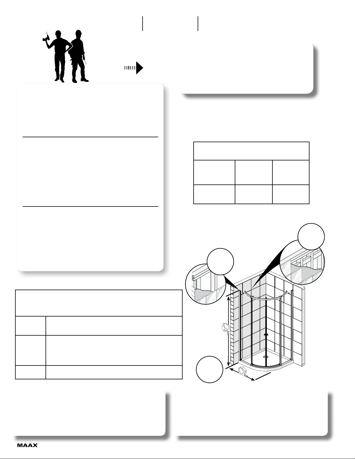
A two person installation is recommended.
Se recomienda realizar la instalacion
entre dos personas.
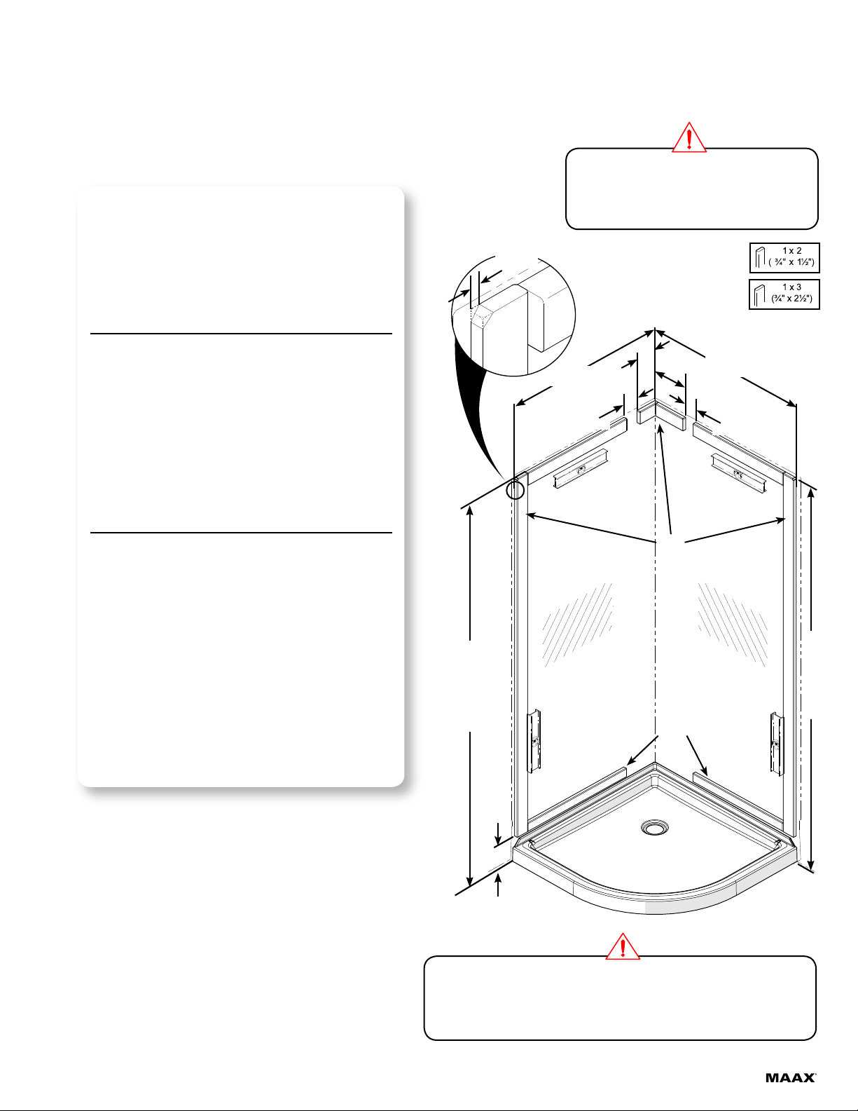
Before beginning the installation, make sure that the door
and panel fit within the shower enclosure. To do so, measure
the height, width and depth of the shower enclosure, and
compare these measures to those of the door and panel.
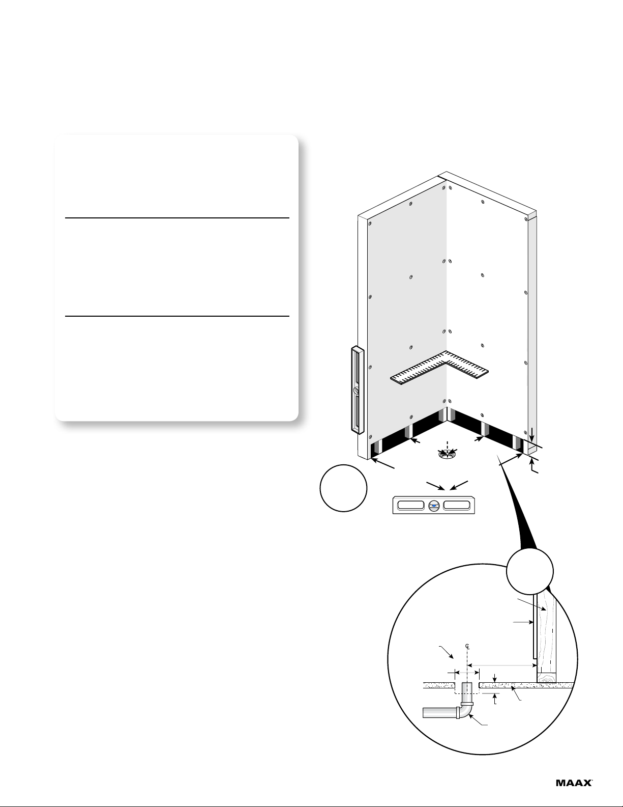
Horizontal and vertical studs are needed on the back and side
walls in order to install the water fixtures and accessories.
See appropriate installation guides.
Double the studs where the wall jambs will be installed.
Antes de comenzar la instalación, asegúrese de que la puerta
y el panel se ajusten a la cabina de ducha. Mida la altura,
el ancho y la profundidad de la cabina de ducha y compare
esas medidas con las de la puerta y el panel.
Se necesitan montantes horizontales y verticales en la
pared trasera y en las paredes laterales para poder instalar
los accesorios de plomería. Ver las guías de instalación
apropiadas.
Duplique los montantes en los lugares en los que se
instalarán las jambas murales.
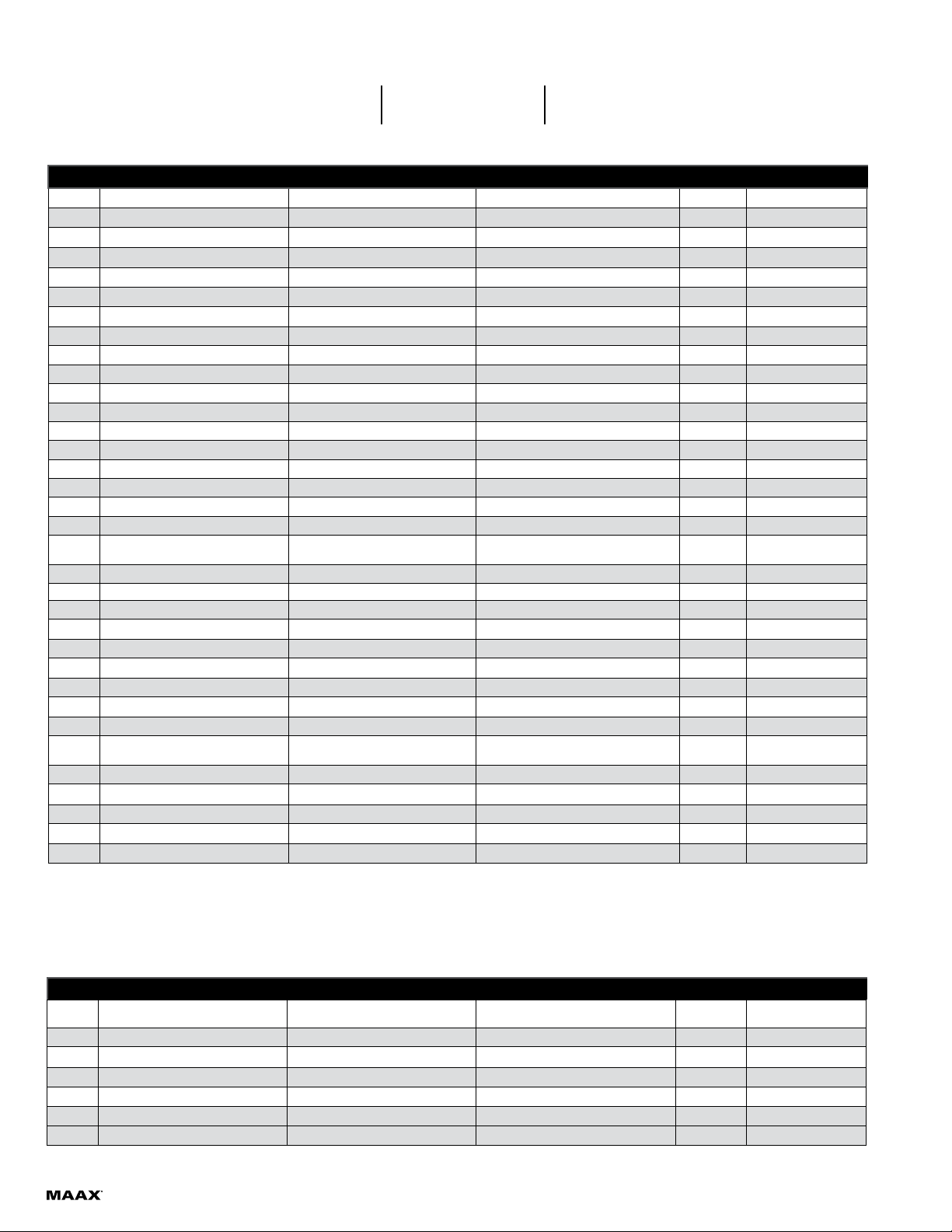
38" x 38" 75" 38 1/16"
3 x 1
74 1/8" (QTY/CANT=2)
27 3/4" (QTY/CANT=1)
23 3/4" (QTY/CANT=1)
7 1/4" (QTY/CANT=1)
4" (QTY/CANT=1)
2 x 1 27 3/4" (QTY/CANT=1)
23 3/4" (QTY/CANT=3)
INSTALLATION WITH OPTIONAL WALLS
Follow the steps from page 7. Skip page 12.
INSTALLATION AVEC DES MURS EN OPTION
Suivre les étapes à partir de la page 7. Ignorez la page 12.
INSTALACIÓN CON MUROS OPCIONALES
Seguir las etapas a partir de la página 7. Ignorar la página 12.
STEPS/ÉTAPES/PASOS:
INSTALLATION WITHOUT OPTIONAL WALLS
Follow the step from page 7, then skip to page 12.
INSTALLATION SANS MURS EN OPTION
Suivez l'étape de la page 7, puis passez à la page 12.
INSTALACIÓN SIN MUROS OPCIONALES
Seguir la etapa de la página 7, entonces pasar a la página 12.
STEPS/ÉTAPES/PASOS:

1
STEP
ÉTAPE
ETAPA
If they are covered, remove finished wall to expose
bottom of studs. Confirm that the studs are vertical
(plumb) within 3/8" and square.
The drain pipe should be 2" diameter (outside diameter
should be 2-3/8") and centered 12⅛" from the studs. The
top of the pipe should be smooth (free of burr or are)
and straight (not on an angle).
Si los montantes en madera esta cubiertos por el muro
cortarlo tal como sale ilustrado en la vista y vericar si
los montantes estan verticales con la ayuda de un nivel
(tolerancia 3/8").
El tubo de desagüe debe tener 2 pulgadas de diámetro
interior (diámetro exterior de 2 3/8") y estar centrado
a 12⅛" de los montantes o jambas murales. La
parte superior del tubo debe ser lisa (sin rebabas ni
ensanches) y recta (no angulosa).
5"
(127 mm)
2 1/4"
(57 mm)
Drain pipe
Drain
Tubo de desagüe
Wall Stud (Framing)
Montant mural (Structure)
Montantes murales (estructura)
Sub floor
Faux plancher
Contrapiso
Finished wall
Revêtement de finition
Revestimiento de acabado
12 1/8"
(308 mm)
Shower base
Base de douche
Base de ducha
12⅛"
4½
38¼"
(972mm)
38¼"
(972mm)
12⅛"
WATERPROOF GYPSE
GYSPE ETANGE
YESO IMPERMEABLE

NOTE
REMARQUE
NOTA
Use shims behind the fastening ange as required.
Utilizar cuñas de madera detrás de la brida de jación
si es necesario.
Ø3/16" Hand tighten only!
Apretar solamente con la mano
#8 x 1 1/4"
Flat Head Screw (recommended)
Tornillo de cabeza plana (recomandado)
1
Complete drain assembly (refer to step 2, ASSEMBLY AND
INSTALLATION of the instructions enclosed in the drain
packaging).
Install the base (1) directly against the studs and conrm
that the drain pipe is centered in the drain head and the
base is leveled in all directions. Please refer to drain
guide for drain installation.
With a 3/16" bit, drill holes in the base flange then secure
the base to the wall studs with #8 x 1¼ " screws. Install wall
finish according to construction standards.
Termine de ensamblar el drenaje (refiérase al Paso 2,
ENSAMBLADO E INSTALACIÓN de las instrucciones
incluidas en el embalaje del desagüe).
Instale la base (1) directamente contra las jambas y
asegúrese de que el tubo de desagüe está centrado
respecto del colector de desagüe y que la base esta
nivelada en todas la direcciones. Consulte la guía del
drenaje para la instalación del desagüe.
Con una broca de 3/16" de diámetro, haga perforaciones
en el reborde de jación de la base. Atornille la base
a las soportes con los tornillos de #8 x 1¼". Instalar
los materiales de acabado mural según las normas de
construcción.
2
STEP
ÉTAPE
ETAPA
The bottom of any hole in the ange
cannot be not less than 8mm (0.3
inches) above the deck or threshold
La parte inferior de cualquier agujero
en la brida no debe ser inferior a 8
mm (0.3 pulgadas) por encima de la
cubierta o el umbral
8 mm min.

3
STEP
ÉTAPE
ETAPA
4¼"(108mm)
37 1/4"
(946mm)
78 ⅜"(1991mm)
1/8"
(3mm)
78 ⅜"(1991mm)
This frame is for these models only
Esta estructura es para estos modelos
the wooden pieces must be fixed on finished wall.
Starting with the longest vertical pieces, fasten wood
pieces as shown. Make sure all wood pieces are level.
File the upper corner of the vertical parts in order
to facilitate the shower installation.
Install the remaining reinforcement pieces as illustrated.
Determine location of faucets. Note: The shaded zones
correspond to the recommended position for faucets.
1" x 2" and 1" x 3" are nominal values of standard lumber.
Las partes de madera deben asentarse sobre una pared
pulida.
Empiece con las dos piezas verticales más largas. Fije
las piezas de madera que conforman el contorno de la
ducha en los lugares indicados, tal como se muestra.
Asegúrese de que todas la piezas de madera estén
niveladas. Nota: Lime la esquina superior de las piezas
verticales con el objeto de facilitar la instalación de la
ducha.
Fije las piezas de refuerzo restantes tal y como aparece
en el dibujo.
Determine la ubicación de los grifos. Nota: las áreas
sombreadas corresponden a la ubicación recomendada
para la grifería.
1" x 2" y 1" x 3" son valores nominales para madera.
Always take the vertical measurements from the oor to the top of the stud
Tome siempre las medidas verticales desde el suelo hasta la parte
superior de las piezas de madera
37 1/4"
(946mm)
8"
(203mm)
3"
(76mm)
3"
(76mm)
4"
(102mm)
1 x 3
1 x 2

4
STEP
ÉTAPE
ETAPA
Remove the plastic wrap.
Align the walls (35-36) and the caddy (37) on
a flat surface. Drill holes on the imprints with a
7/32" brill bit as shown.
Apply a continuous bead of silicone inside the
bolts from top to bottom on one of the wall
anges.
Assemble walls with the #10-32 x 5/8" screws
(6), 1/4" washers (7) and #10-32 nuts (8)
provided.
Retirar la película de plástico.
Alinear los muros (35-36) y el caddy (37) contra
una superficie plana. Perforar con una broca
de 7/32" las muescas de perforación como sale
ilustrado.
Aplique un cordón continuo de silicona en el
interior de los pernos de arriba a abajo en una
de las bridas de pared.
Ensamble las paredes con los tornillos #10-32 x
5/8" (6), las arandelas de 1/4" (7) y las tuercas
de #10-32 (8) suministradas.
35
37
REAR VIEW
VUE POSTÉRIEURE
VISTA POSTERIOR
When inserting screws into plastic parts always
use a screwdriver to avoid damage.
Al insertar los tornillos en piezas plásticas siempre
utilizar un destornillador para evitar dañarlas.
Before working with plastic walls, allow time to
adjust to ambient temperature.
Antes de trabajar con los muros de plástico, dejar
que se ajusten a la temperatura ambiente.
39
40 38
36
35
37
37
36
Manipulate the walls with care. They may have
sharp edges.
Manipular los muros con cuidado. Ellos pueden
tener bordes alados.

5
STEP
ÉTAPE
ETAPA
Slide the shower into its location. The wood framing
built in step 1 should fall inside raised sections of the
walls without interference. If there is any interference
adjust framing accordingly to remove any stress from walls.
Drill holes through the upper lip of the walls (35), (36)
and (37) using a 3/32" drill bit, evenly distributed on
the upper lip.
Fasten the top of the walls with the # 8 x 1¼" stainless
steel screws (41) using a screwdriver. DO NOT
SCREW THE WALLS WITH AN ELECTRIC DRILL.
Deslice la ducha en su sitio. La estructura de madera
construida en el paso 1 debe caer dentro de las
secciones elevadas de las paredes sin interferencia.
Si hay interferencia ajustar la estructura en
consecuencia para eliminar cualquier tensión de las
paredes.
Perfore agujeros a través del borde superior de
las paredes de ducha (35), (36) y (37) con broca
de 3/32", distribuidos uniformemente en el labio
superior.
Usando un destornillador fije la parte superior de las
paredes con los tornillos # 8x1¼" (41). NO FIJAR LOS
MUROS CON UN TALADRO ELÉCTRICO.
3536
1
41
To protect the base nish use a piece of card-
board cut from the shipping box during installation
Para proteger el acabado de la base utilizar un pe-
dazo de cartón recortado de la caja de transporte
durante la instalación
When inserting screws into walls panel always
use a screwdriver to avoid damaging the wall.
Al insertar los tornillos en el panel de las paredes
siempre utilizar un destornillador para evitar dañar
la pared.
37

NOTE
REMARQUE
NOTA
Use shims behind the fastening ange as required.
Utilizar cuñas de madera detrás de la brida de jación
si es necesario. Ø3/16" Hand tighten only!
Apretar solamente con la mano
#8 x 1 1/4"
Flat Head Screw (recommended)
Tornillo de cabeza plana (recomandado)
1
6
STEP
ÉTAPE
ETAPA
Install the base (1) directly against the studs and conrm
that the drain pipe is centered in the drain head and the
base is leveled in all directions. Please refer to drain guide
for drain installation.
With a 3/16" bit, drill holes in the base flange then secure
the base to the wall studs with #8 x 1¼ " screws. Install wall
finish according to construction standards.
Instale la base (1) directamente contra las jambas y
asegúrese de que el tubo de desagüe está centrado
respecto del colector de desagüe y la base esta centrada
en todas las direcciones. Consulte la guía del drenaje
para la instalación del desagüe.
Con una broca de 3/16" de diámetro, haga perforaciones
en el reborde de jación de la base. Atornille la base
a las soportes con los tornillos de #8 x 1¼". Instalar
los materiales de acabado mural según las normas de
construcción.

7
STEP
ÉTAPE
ETAPA
Position and level both wall jambs (5) 5/8" from the
outside edge of the shower base.
Mark the fastening holes.
Drill the wall covering. [For ceramics always use a
ceramics 1/4" drill bit].
Fill the holes with a generous amount of silicone and
apply silicone sealant behind the wall jamb (5).
Fasten the wall jambs (5) with the provided screws
(22).
Ubicar las jambas murales (5) [lado panel fijo] a 5/8"
desde exterior del reborde de la base de la ducha y
ponerlas a nivel.
Marcar la ubicación de los agujeros de fijación.
Taladrar el revestimiento de la pared. [Para taladrar
azulejos, use siempre una broca para cerámica de
1/4".]
Llene los agujeros con abundante silicona y aplicar
silicona detrás de las jambas murales (5).
Fije las jambas murales (5) con los tornillos provistos
(22).
INSIDE
INTÉRIEUR
INTERIOR
5
5
NOTE
REMARQUE
NOTA
28
If no studs are behind the wall covering use the wall anchors (28)
when fastening the wall jambs (5). Not required with optional wall.
Si no hay montantes detrás del revestimiento, usar anclages (28)
para sujetar las jambas murales (5). No son necesarios con los
muros opcionales.
5
22
⅝"

5
4
4
4
8
STEP
ÉTAPE
ETAPA
Insert the fixed panels (4) in the wall jambs (5)
as shown. Slightly lift the fixed panels (4) to set
in position the two door guides (6) (7) then the
threshold (8) .
To confirm the position of the components the
glass must be parallel to the base.
Remove the door guides (6), (7) and the threshold
(8) and apply silicone under them. Place them
back in position as shown. Use masking tape to
keep threshold in position.
Insertar los paneles fijos (4) en la jambas murales
(5) tal como esta ilustrado. Levantar ligeramente
los paneles fijos (4) para fijar la posición de las dos
guías de la puerta (6) (7) y después del umbral (8).
Para confirmar la posición de los componentes, el
vidrio debe estar paralelo a la base.
Retirar la parte hueca de la guía.
Retirar las guías de puerta (6), (7) y umbral (8).
Aplicar silicona debajo de estas piezas y volverlas
a colocar en posición tal como sale ilustrado. Usar
cinta adhesiva para mantener el umbral en posición.
6
4
6
4
6
8
7
8
77

9
STEP
ÉTAPE
ETAPA
Fasten the long posts (9) to the fixed panels (4)
using the washers (10), the bushing (11) and the
glass screws (12) in the holes closer to the shower
walls as shown.
Insert end bumpers (16) to both ends of the track (15).
Fasten with the provided nuts (29), washers (30),
screws (31) and chrome caps (32) as shown.
Put track (15) with the cutout upwards in place and
keep it in position with the help of two tie wraps as
shown.
Asegurar los postes largos (9) a los paneles jos
(4) utilisando las arandelas (10), el cojinete (11) y
los tornillos para vidrio (12) en los agujeros más
cercanos a las paredes de la ducha tal como sale
ilustrado.
Insertar los parachoques extremos (16) en los
extremos del riel (15). Fijar con las tuercas (29), las
arandelas (30), los tornillos (31) y los cubretornillos
(32) incluidos tal como sale ilustrado.
Colocar el riel (15) con el recorte hacia arriba en su
lugar y mantenerlo en posición con dos cierres de
lazo como sale ilustrado.
9
4
12
11
10
29
30 31 32
16
15
9
9
44
15
15
15

10
STEP
ÉTAPE
ETAPA
Fasten the long posts (9) to the track (15) using the
adjustment bushing (13) and the glass screws (12) in
the holes closer to the track ends as shown. DO NOT
TIGHTEN COMPLETELY. Level the track (15) and then
tighten completely.
Remove the tie wraps. Assemble the short posts (18)
and fasten with the provided screws (19), washers (10),
bushing (11) and adjustment bushing (13) as shown.
Check again that the rail is leveled.
Asegurar los postes largos (9) al riel (15) utilisando los
cojinetes de ajuste (13) y los tornillos para vidrio (12)
en los agujeros más cercanos a los extremos del riel tal
como sale ilustrado. NO AJUSTAR COMPLETAMENTE.
Nivelar el riel (15) y después ajustar completamente.
Retirar los cierres de lazo. Ensamblar y asegurar los
postes cortos (9) utilisando los tornillos (19) las arandelas
(10), el cojinete (11) y el cojinete de ajuste (13) tal como
sale ilustrado. Revisar de nuevo que el riel este nivelado.
12
13
12
13
13
10
17
11
18
19
13
10
11
17
18
19

11
STEP
ÉTAPE
ETAPA
Insert and tighten the rollers (20) in top holes of
the doors (2) and (3). thighten with the provided
wrenches (33) as shown.
Assemble the door knobs (26) to the doors (2) and
(3) as shown.
Insert a drip shield (21) at the bottom of each door.
Ensamblar cada un de los rodillos (20) a través
de los agujeros en la parte superior de las
puertas (2) y (3). Apretar con las llaves incluidas
(33) tal como sale ilustrado.
Ensamblar los tiradores (26) a las puertas (2) y
(3) tal como sale ilustrado.
Insertar un protector de goteo (21) por debajo de
cada puerta como sale ilustrado.
2 3
2
21
3
21
2
20
3
20
26
INSIDE VIEW
VUE INTÉRIEURE
VISTA INTERIOR
33
33
TOP VIEW
VUE SUPÉRIEURE
VISTA SUPERIOR

12
STEP
ÉTAPE
ETAPA
Insert door rollers (20) into track (15) with
magnets facing each other, one door at a time.
Start with the roller fartest from the magnet,
insert it thru the cutout in the middle of the
track. Once on the rail slide the door outward
to insert the other roller as shown. Repeat
the process for the second door. Make sure
to engage the bottom of the doors in the door
guides (6) and (7).
Insert the middle bumper (24) into the cutout
in track (15). Jam the middle bumper on
the return lip of track and push the upper
part of the bumper against the rail to nalise
installation. Slide the middle bumper cover
(23) downward into the middle bumper (24) to
secure them in place as shown.
Inserte rodillos de la puerta (20) en el riel (15)
con los imanes cara a cara, una puerta a la
vez. Comenzar con un rodillo, insertandolo a
través del recorte en el centro del riel. Una vez
en el carril deslizar la puerta para insertar el
otro rodillo como se muestra. Repita el proceso
para la segunda puerta. Asegurese de insertar
las puertas en las guías de puerta (6) y (7).
Inserte el parachoque del medio (24) en la
ranura del riel (15). Colocar la parte baja del
parachoques (24) sobre el labio de retorno
del riel y enseguida oprimir la parte alta del
parachoques contra el riel para finalizar la
instalación. deslice la cubierta del parachoques
(23) de arriba hacia abajo sobre el parachoque
(24) como se muestra.
20
15
15
cutout
Recorte
INSIDE
INTÉRIEUR
INTERIOR
15
20
INSIDE
INTÉRIEUR
INTERIOR
24
23
3
7
4
23
24

13
STEP
ÉTAPE
ETAPA
25
Insert Gaskets (25) on both doors (2) and (3)
as shown.
Cut the gaskets to clear the rail.
Insertar las juntas de estanqueidad (25)en las
dos puertas (2) y (3) tal como sale ilustrado.
Cortar las juntas de estanqueidad para
despejar el riel.
25

14
STEP
ÉTAPE
ETAPA
When opening the doors (2) and (3) verify if
they slide smoothly in the door guides. If they do
not, using the wrench for eccentric adjustment
(33) adjust the doors height with the rollers
(20). Make sure the fixed panels (4) are level in
the wall jambs (5), adjust as necessary. When
closing the doors, make sure the magnets close
properly.
Put screw covers on door rollers (20).
clés de réglage excentrique
(33)
Al abrir las puertas (2) y (3) verificar si rozan
las guías de la puerta. En caso afirmativo
ajustar con las llaves para ajuste excéntrico
(33) la altura de la puerta con los rodillos (20).
Asegurarse que los paneles fijos (4) estén a
nivel. Ajustar en caso de necesidad. Al cerrar las
puertas asegúrese de que los imanes se cierran
correctamente.
Ponga las cubiertas de tornillo en los rodillos de
la puerta.
INSIDE VIEW
VUE INTÉRIEURE
VISTA INTERIOR
33
33
20
INSIDE VIEW
VUE INTÉRIEURE
VISTA INTERIOR
This manual suits for next models
1
Table of contents
Other MAAX Shower Cabin manuals
Popular Shower Cabin manuals by other brands

Jacuzzi
Jacuzzi Bonaire 7236 Shower Base DD26 Specification sheet

Porcelanosa
Porcelanosa SYSTEMPOOL MODUL Conjunto PRE-INSTALLATION AND INSTALLATION MANUAL

THE SHOWER LAB
THE SHOWER LAB VIEW 19F manual

Better Bathrooms
Better Bathrooms Trinity Premium instructions

Insignia
Insignia INS9001 installation manual

Welltime
Welltime Florenz 604970 Installation instruction

Wellis
Wellis Sorrento plus 90 Instruction guide

NewLine
NewLine 900 instruction manual

Dreamline
Dreamline AQUA-Q SWING SD-373472Q Series installation instructions

OVE
OVE CHARLOTTE 60 TD instruction manual

ERLIT
ERLIT ER 5512PL Installation and operation instruction

OVE
OVE SWIFT INSTALL 34 installation manual