2 ©2012MadCowRocketry™ AGM-33PIKE™Assembly AGM-33PIKE™Assembly ©2012MadCowRocketry™ 3
Please make sure you read all directions and understand how to assemble your model
beforeyoustartconstruction.Itisalsoagoodideatotestteachpartbeforeassembly.
Fiberglass parts still contain small amounts of mold release and other materials on the
surfacethatwillinhibitadhesivesand/orpaint.Itisimportanttocleaneachpartprior
to assembly with a solution of 1 part rubbing alcohol, 3 parts water and a drop of dish
washingsoap.IMPORTANT:donotsandanypartsuntilafteryouhavecleanedthem-
youwillembedthematerialsyouaretryingtocleanmakingitdifculttoclean.
TheG10partswillhaveholdingtabsleftoverfromtheCNCmachine.Thesesmalltabs
will need to be sanded off before assembly. Before assembling any part with epoxy,
roughupthesurfacetobeepoxiedusingcoursesandpaper.ThescratchesintheG10
surface will give the epoxy something to grab onto.
Step1–MotorMountAssembly
Testtthecenteringringsoverthemotormounttubeandsandifnecessary.Alsotest
tthecenteringringsinthebodytubeandsandifnecessary.Takeoneofthecentering
ringsanddrilla1/4”holefortheeyebolt.IMPORTANT:makesuretheholeiscentered
between the inner and outer edge of the ring so the nut on the eyebolt will not interfere
withthebodytubeormotortubelater.Theringwiththe1/4”holeforaneyeboltwillbe
the forward ring. Mount the eyebolt using the two nuts as shown in the forward ring hole.
Applysomeepoxytothenutstoensuretheywillnotcomelooselater.IMPORTANT:
Make sure the eyebolt and nut are aligned properly so the motor assembly can
slide into the body tube.
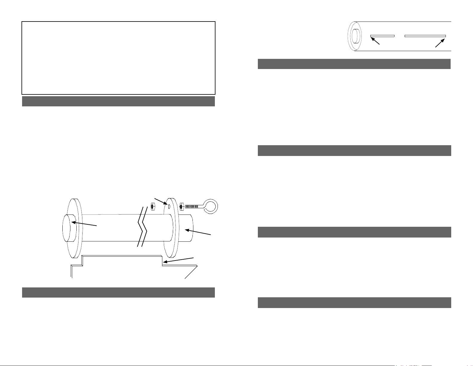
Spread some epoxy on the outside of one end of the motor tube and slide the ring
(without the hole) until there is approximately 1/2” of motor tube exposed. Make sure
youcleanthemotortubeofanyepoxysoasnottointerferewiththentangslater.After
the aft ring is dry, make a mark 1” from the other end of the motor tube. Spread some
epoxy on the motor tube and slide the forward ring until it aligns with the mark. VERY
IMPORTANT:
make sure
there is not
any epoxy on
the motor tube
that would
interfere with
the n tangs
later on.
Attachoneend
of the shock
cord to the
eyebolt using an
overhand knot.
Step4–RailButtonAttachment
Mark the CP point along the rail button line you made in the previous step. Make sure
youmeasuretheCPpointfromthetipofthenoseconeandNOTtheendofthebody
tube.Drilla5/64”holeontherailbuttonlinefortheforwardandaftrailbuttons.Theaft
hole should be 1” from the aft end of the body tube and the forward hole should be at the
CPpoint.Applyasmallamountofepoxyintheholesandattachtherailbuttonsusing
the supplied #6 wood screws. Make sure the screw is loose enough for the rail button
to spin freely - this ensures the button is not compressed to the point it will hang on the
rail guide. IMPORTANT: The screw from the forward rail button should be behind
the forward centering ring. If it isn’t, make sure the forward rail button screw
protruding through the body tube doesn’t snag the chute. Epoxy over the screw
to provide a smooth surface. The screw can also be cut shorter.
Step2–InsertMotorTubeAssemblyintoBodyTube
Wrap the shock chord into a small bundle and stuff it inside the motor tube for this next
step.Testtthemotortubeassemblyintothebodytubetoensureasnugt.Sandthe
centeringringsifnecessary.Whenyouaresatisedwiththet,spreadsomeepoxyon
the inside of the body tube and slide the forward centering ring of the motor assembly
into the body tube. Make sure you have the motor assembly facing the right way!
Spread some more epoxy on the inside edge of the body tube before sliding the rear
centering ring into the body tube. Continue sliding the assembly inside the body tube
untiltheaftendofthemotortubeisevenwiththeaftendofthebodytube.It’sagood
ideatotesttanineachslothere
before the epoxy sets. Hold the body
tube with the motor tube assembly down
until the epoxy sets. Make sure the
weightofthemotorassemblydoesn’t
cause it to slide out of alignment.
Step3–FinAssembly
Using a door jam or small section of angle stock, pencil a line halfway between two of the
nsthatextendsfromthefronttothebackofthebodytube.Thislinewillbeusedlater
toaligntherailbuttons.Testteachofthensintotheprecutnslots.Thenshould
seatrmlyagainstthemotortube-sandeachnifnecessary.Whenyouaresatised
withthet,applysomeepoxytotheendofthentangthatwillcontactthemotortube.
Also,spreadathinlayerofepoxyoneachsideofthentang.Slidethenintoplace
andcheckthealignment.Continuerecheckingthenalignmentuntilyouaresurethe
epoxyhasset.Cleananyexcessepoxyfromaroundthenjoint.Youcanclampsome
woodplankstotheforwardandaftnstokeepthemalignedwitheachotherwhilethe
gluesets.Repeatfortheremainingns.Next,applyepoxylletstobothsidesofeach
nbyapplyingathinbeadofepoxyatthen-bodytubejoing.Carefullysmooththe
epoxylletswithyourngerbeforetheepoxysets.Alloweachllettosetbeforerotating
theairframeforthenextllet.
Step5–BalanceandNoseConeAssembly
Mount the remaining eyebolt using the nuts and washer in the nose cone bulkplate.
Applysomeepoxytothenutsoitwillnotcomelooselater.Testtthebulkplateinthe
baseofthenoseconeandsandifnecessary.Atthispoint,packthechuteandassemble
therocket.Insertthelargestmotorthatyouintendtoy(orsimulatetheweightwithan
appropriate substitute) and ensure that the CG is at least 1 body diameter in front of the
estimatedCPpointspeciedontherstpage.TheCPshouldbemeasuredfromthetip
ofthenosecone.IftheCGistoofarback,addweightinsidethenoseconeandsecure
withepoxy.WhenyouaresatisiedwiththeCG,epoxythebulkplateintothebaseofthe
noseconeleavingatleasta1/4”liptoapplyallet.Next,applyalletofepoxyaround
the bulkplate and nose cone shoulder joint.
Step6–FlyingYourModel
Attachtheendoftheshockcordandtheparachutetothenoseconeeyebolt.You
can also attach the chute protector to the shock cord just below the nose cone. When
packing your chute, wrap the chute protector around the chute with the opening in the
chuteprotectorfacingforward.Alwaysmakesureyourchuteiswellprotectedasthehot
ejection motor gasses will melt the nylon chute.
1/2” Exposed
1” Exposed
Forward Ring Hole
Fin
FinTang
Ensureringsareclearofthenslots


