2 ©2012 MadCow Rocketry™ Piranha™ Assembly Piranha™ Assembly ©2012 MadCow Rocketry™ 3
Please make sure you read all directions and understand how to assemble your model
beforeyoustartconstruction.Itisalsoagoodideatotestteachpartbeforeassembly.
Fiberglass parts still contain small amounts of mold release and other materials on the
surface that will inhibit adhesives and/or paint. It is important to clean each part prior
to assembly with a solution of 1 part rubbing alcohol, 3 parts water and a drop of dish
washing soap. IMPORTANT: do not sand any parts until after you have cleaned them -
youwillembedthematerialsyouaretryingtocleanmakingitdifculttoclean.
The G10 parts will have holding tabs left over from the CNC machine. These small tabs
will need to be sanded off before assembly. Before assembling any part with epoxy,
rough up the surface to be epoxied using course sandpaper. The scratches in the G10
surface will give the epoxy something to grab onto.
Step 1 – Motor Mount Assembly
Step 4 – Rail Button Attachment
Mark the CP point along the rail button line you made in the previous step. Make sure
you measure the CP point from the tip of the nose cone and NOT the end of the body
tube. Drill a 5/64” hole on the rail button line for the forward and aft rail buttons. The
aft hole should be 1/2” from the aft end of the body tube and the forward hole should be
at the CP point. Apply a small amount of epoxy in the holes and attach the rail buttons
using the supplied #6 wood screws. Make sure the screw is loose enough for the rail
button to spin freely - this ensures the button is not compressed to the point it will hang
on the rail guide. IMPORTANT: The screw from the forward rail button should be
behind the forward centering ring. If it isn’t, make sure the forward rail button
screw protruding through the body tube doesn’t snag the chute. Epoxy over the
screw to provide a smooth surface. The screw can also be cut shorter.
Step 2 – Insert Motor Tube Assembly into Body Tube
Wrap the shock chord into a small bundle and stuff it inside the motor tube for this next
step.Testtthemotortubeassemblyintothebodytubetoensureasnugt.Sandthe
centeringringsifnecessary.Whenyouaresatisedwiththet,spreadsomeepoxyon
the inside of the body tube and slide the forward centering ring of the motor assembly
into the body tube. Make sure you have the motor assembly facing the right way!
Spread some more epoxy on the inside edge of the body tube before sliding the rear
centering ring into the body tube. Continue sliding the assembly inside the body tube
until the aft end of the motor tube is even with the aft end of the body tube. It’s a good
Ensureringsareclearofthenslots
ideatotesttanineachslothere
before the epoxy sets. Hold the body
tube with the motor tube assembly down
until the epoxy sets. Make sure the
weight of the motor assembly doesn’t
cause it to slide out of alignment.
Step 3 – Fin Assembly
Using a door jam or small section of angle stock, pencil a line halfway between two of
thensthatextendsfromthefronttothebackofthebodytube.Thislinewillbeused
latertoaligntherailbuttons.Testteachofthensintotheprecutnslots.Then
shouldseatrmlyagainstthemotortube-sandeachnifnecessary.Whenyouare
satisedwiththet,applysomeepoxytotheendofthentangthatwillcontactthe
motortube.Also,spreadathinlayerofepoxyoneachsideofthentang.Slidethen
intoplaceandcheckthealignment.Continuerecheckingthenalignmentuntilyouare
suretheepoxyhasset.Cleananyexcessepoxyfromaroundthenjoint.Repeatfor
theremainingns.Next,applyepoxylletstobothsidesofeachnbyapplyingathin
beadofepoxyatthen-bodytubejoing.Carefullysmooththeepoxylletswithyour
ngerbeforetheepoxysets.Alloweachllettosetbeforerotatingtheairframeforthe
nextllet.
Step 6 – Flying Your Model
Attach the end of the shock cord and the parachute to the nose cone. You can also
attach the chute protector to the shock cord just below the nose cone. When packing
your chute, wrap the chute protector around the chute with the opening in the chute
protector facing forward. Always make sure your chute is well protected as the hot
ejection motor gasses will melt the nylon chute.
Step 5 – Balancing Your Model
Assembleyourmodelandinsertthelargestmotoryouintendtoy(orsimulatethe
weight with a substitute) and ensure that the CG is at least 1 body diameter in front of
theestimatedCPpointspeciedontherstpage.TheCPpointismeasuredfromthe
tip of the nose cone. If the CG is behind the desired point, add weight inside the nose
cone by pouring lead shot into the nose cone tip and adding some epoxy. IMPORTANT:
Screw in a screw through the plastic nose cone into the lead to hold it in place.
Grind or cut off the screw head before lling and applying the nose cone nish.
The epoxy will not stick to the inside of the nose cone and if you do not anchor
with a screw, the liftoff force will cause the weight to become dislodged causing
an unstable model.
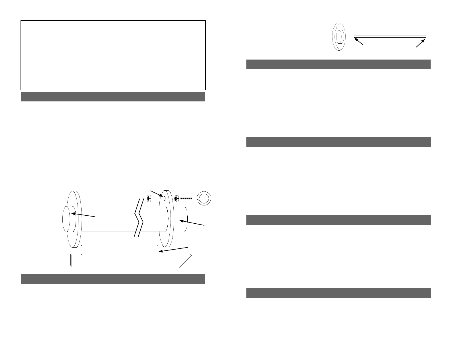
Testtthecenteringringsoverthemotormounttubeandsandifnecessary.Alsotest
tthecenteringringsinthebodytubeandsandifnecessary.Takeoneofthecentering
rings and drill a 1/4” hole for the eyebolt. IMPORTANT: make sure the hole is centered
between the inner and outer edge of the ring so the nut on the eyebolt will not interfere
with the body tube or motor tube later. The ring with the 1/4” hole for an eyebolt will be
the forward ring. Mount the eyebolt using the two nuts as shown in the forward ring hole.
Apply some epoxy to the nuts to ensure they will not come loose later. IMPORTANT:
Make sure the eyebolt and nut are aligned properly so the motor assembly can
slide into the body tube.
Spread some epoxy on the outside of one end of the motor tube and slide the ring
(without the hole) until there is approximately 1/2” of motor tube exposed. Make sure
youcleanthemotortubeofanyepoxysoasnottointerferewiththentangslater.After
the aft ring is dry, make a mark 1” from the other end of the motor tube. Spread some
epoxy on the motor tube and slide the forward ring until it aligns with the mark. VERY
IMPORTANT:
make sure
there is not
any epoxy on
the motor tube
that would
interfere with
the n tangs
later on.
Attach one end
of the shock
cord to the
eyebolt using an
overhand knot.
1/2” Exposed
1” Exposed
Forward Ring Hole
Fin
Fin Tang


