2 ©2015 MadCow Rocketry™ mini Aerobee 150A mini Aerobee 150A ©2015 MadCow Rocketry™ 3
Please make sure you read all directions and understand how to assemble your model
beforeyoustartconstruction.Itisalsoagoodideatotestteachpartbeforeassembly
–somemanufacturingtolerancesmayrequirelightsandingbeforenalassembly.
Laser cut parts will exhibit varying amounts of charring on the edges depending on the
density of the plywood. The charred edges do not interfere with bonding and do not
need to be cleaned before assembly. In most cases the charring will be cleaned up
duringsandingfornishingandpainting.
Step 1 – Motor Mount Assembly
Step 2 – Insert Motor Tube Assembly into Body Tube
Testteachofthensintotheprecutnslots.Becauseplywoodthicknessvaries,you
may need to sand the slot to the correct width. Wrap the shock chord into a small bundle
andstuffitinsidethemotortubeforthisnextstep.Testtthemotortubeassemblyinto
thebodytubetoensureasnugt.Sandthecenteringringsifnecessary.Whenyou
aresatisedwiththet,spreadsomeepoxyontheinsideofthebodytubeandslidethe
forward centering ring of the motor assembly into the body tube. Make sure you have
the motor assembly facing the right way! Spread some more epoxy on the inside
edge of the body tube before sliding the rear centering ring into the body tube. Continue
Ensureringsareclearofthenslots
sliding the assembly inside the body tube
until the aft centering rings are just clear
ofthenslots.It’sagoodideatotestt
anineachslotherebeforetheepoxy
sets. Hold the body tube with the motor
tube assembly down until the epoxy sets.
Make sure the weight of the motor tube
doesn’t cause it to slide out of alignment.
Step 3 – Fin Assembly
Using a door jam or small section of angle stock, pencil a line halfway between two of the
nsthatextendsfromthefronttothebackofthebodytube.Thislinewillbeusedlater
to align the launch lugs. Additionally, pencilalinefromthefrontofeachntothe
end of the tubes to aid in aligning the conduits later. Testteachofthensinto
theprecutnslots.Thenshouldseatrmlyagainstthemotortube-sandeachnor
slotifnecessary.Whenyouaresatisedwiththet,applysomeepoxytotheendofthe
ntangthatwillcontactthemotortube.Also,spreadathinlayerofepoxyoneachside
ofthentang.Slidethenintoplaceandcheckthealignment.Continuerechecking
thenalignmentuntilyouaresuretheepoxyhasset.Cleananyexcessepoxyfrom
aroundthenjoint.Repeatfortheremainingns.Next,applyepoxylletstobothsides
ofeachnbyapplyingathinbeadofepoxyatthen-bodytubejoing.Carefullysmooth
theepoxylletswithyourngerbeforetheepoxysets.Alloweachllettosetbefore
rotatingtheairframeforthenextllet.
Testtcenteringringsoverthemotormounttubeandsandmotortubeifnecessary.Also
testtthecenteringringsinthebodytubeandsandifnecessary.Spreadsomeepoxyon
the outside of one end of the motor tube and slide the ring (without the notch) until there
is approximately 1/2” of motor tube exposed. Make sure you clean the motor tube of any
epoxysoasnottointerferewiththentangslater.Aftertheaftringisdry,makeamark
1/2” from the other end of the motor tube. Spread some epoxy on the motor tube and
slide the forward ring until it aligns with the mark. VERY IMPORTANT: make sure there
is not any epoxy on the motor tube that would interfere with the n tangs later on.
Fin
Fin Tang
1/2” Exposed
1/2” Exposed
Forward Ring Notch
Push cord in corner and
tack with epoxy
The shock cord in this kit consists
of a shorter section of Kevlar and a
longer section of nylon cording. The
two sections should be tied together
using a single overhand, ring bend
ordoublesherman’sknot.The
Kevlar section will be attached to
the motor mount and the nylon
section will be attached to the nose
cone.
Wrap the end of the Kevlar shock
cord around the forward end of the
motor tube and tack in place with
CA.Makesurethecordlaysat
enough so it will not interfere with
the body tube when you slide the
motor tube inside. Apply some
epoxy to the cord to hold it in place.
Make sure the cord is secure
and will not come loose later with
ejection forces that will pull on the
shock cord. Step 5 – Launch Lug
Mark the CP point along the launch lug line you made in the previous step. Make sure
you measure the CP point from the tip of the nose cone and NOT the end of the body
tube. Apply a small amount of epoxy on the launch lug line about ¾” long on the CP
mark. Press one of the launch lugs into the epoxy and ensure that it is aligned with the
launch lug line previously drawn on the body tube. You can site down the tube and look
through the launch lug to make sure it is straight. Similarly epoxy the second launch
lugabout2”fromtheaftendofthebodytube(alignedwiththeaftendofthens).Site
down both launch lugs and make sure they are both aligned. If you have a ¼” launch
rod, you can use this to ensure that both lugs are aligned properly.
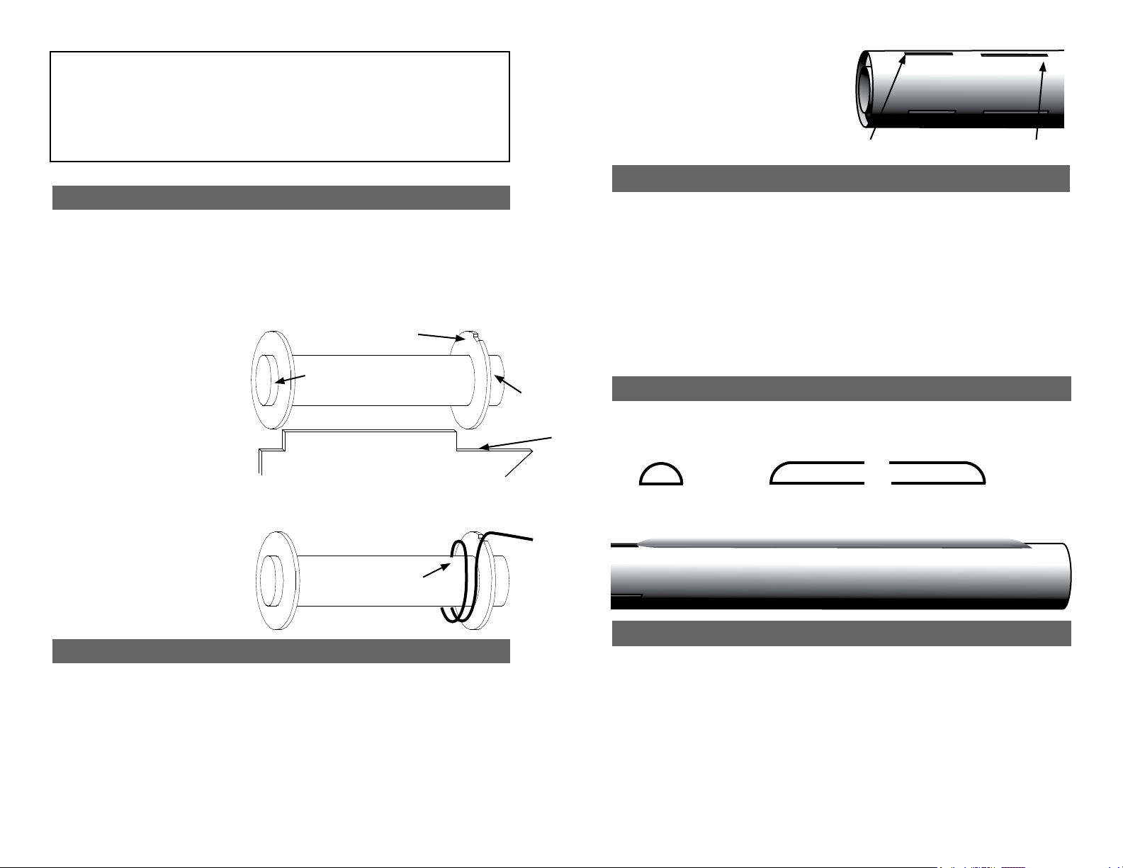
Step 4 - Conduit Assembly
Side View
End View
Trim each conduit balsa stick to 17” and carefully sand the conduits so they
form a 1/2 round conduit as shown. Also taper the fore and aft end of the
conduit as shown.
Glue each conduit to the body tube carefully aligned them to the marks you
made earlier.


