2 ©2010 MadCow Rocketry™ Squat™ Assembly Squat™ Assembly ©2010 MadCow Rocketry™ 3
Please make sure you read all directions and understand how to assemble your model
beforeyoustartconstruction.Itisalsoagoodideatotestteachpartbeforeassembly
–somemanufacturingtolerancesmayrequirelightsandingbeforenalassembly.
Laser cut parts will exhibit varying amounts of charring on the edges depending on the
density of the plywood. The charred edges do not interfere with bonding and do not
need to be cleaned before assembly. In most cases the charring will be cleaned up
duringsandingfornishingandpainting.
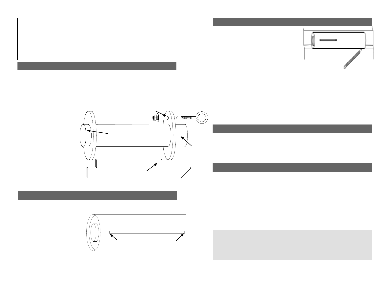
Step 1 – Motor Mount Assembly
Testtthecenteringringsoverthemotormounttubeandsandifnecessary.Alsotestt
the centering rings in the body tube and sand if necessary. One of the rings will have a
hole for an eyebolt to attach the shock cord - this will be the forward ring. Spread some
epoxy on the outside of one end of the motor tube and slide the ring (without the hole)
until there is approximately 1/2” of motor tube exposed. Make sure you clean the motor
tubeofanyepoxysoasnottointerferewiththentangslater.Aftertheaftringisdry,
make a mark 1/4” from the other end of the motor tube. Spread some epoxy on the
motor tube and slide the forward
ring until it aligns with the mark.
VERY IMPORTANT: make
sure there is not any epoxy
on the motor tube that would
interfere with the n tangs
later on. Also make sure the
n tangs will t between the
two centering rings.
Mount the eyebolt using the nut
and washer in the forward ring
hole. Apply some epoxy to the
nut to ensure it will not come
loose later. Attach one end of
the shock cord to the eyebolt
using an overhand knot.
Step 3 – Fin Assembly
Using a door jam or small section of angle stock,
pencilalinehalfwaybetweentwoofthensthat
extends from the front to the back of the body
tube. This line will be used later to align the rail
buttons.
Testteachofthensintotheprecutnslots.
Thenshouldseatrmlyagainstthemotortube-
sandeachnifnecessary.Whenyouaresatised
withthet,applysomeepoxytotheendofthentangthatwillcontactthemotortubeas
wellasthenrootthatwillcontactthebodytube.Also,spreadathinlayerofepoxyon
eachsideofthentang.
Slidethenintoplaceandcheckthealignment.Continuerecheckingthenalignment
untilyouaresuretheepoxyhasset.Cleananyexcessepoxyfromaroundthenjoint.
Repeatfortheremainingns.
Next,applyepoxylletstobothsidesofeachn.Carefullysmooththeepoxylletswith
yourngerbeforetheepoxysets.Alloweachllettosetbeforerotatingtheairframefor
thenextllet.
Step 4 – Rail Button Attachment
Drill a 5/64” hole on the rail button line for the forward and aft rail buttons. These holes
should go into the centering rings. Apply a small amount of epoxy in the holes and
attach the rail buttons using the supplied #6 wood screws. Make sure the screw is loose
enough for the rail button to spin freely - this ensures the button is not compressed to the
point it will hang on the rail guide.
Step 2 – Insert Motor Tube Assembly into Body Tube
Wrap the shock chord into a small bundle and stuff it inside the motor tube for this next
step.Testtthemotortubeassemblyintothebodytubetoensureasnugt.Sandthe
centering rings if necessary.
Whenyouaresatisedwiththet,
spread some epoxy on the inside of
the body tube and slide the forward
centering ring of the motor assembly
into the body tube. Make sure you
have the motor assembly facing
the right way! Spread some more
epoxy on the inside edge of the
body tube before sliding the rear centering ring into the body tube. Continue sliding the
assembly inside the body tube until the aft end of the motor tube is even with the aft end
ofthebodytube.It’sagoodideatotesttanineachslotherebeforetheepoxysets.
Hold the body tube with the motor tube assembly down until the epoxy sets. Make sure
the weight of the motor assembly doesn’t cause it to slide out of alignment.
Ensure centering rings are
clearofthenslots
1/2” Exposed
1/4” Exposed
Forward Ring Hole
Fin Fin Tang
Step 5 – Balancing Your Model
At this point, pack the chute and assemble the rocket. Insert the largest motor that you
intendtoy(orsimulatetheweightwithanappropriatesubstitute)andensurethatthe
CGisforwardofthepointdenedinthespecicationsontherstpage.TheCGshould
bemeasuredfromthetipofthenosecone.IftheCGisbehindthespeciedpoint,
add weight inside the nose cone by pouring lead shot into the nose cone and adding
some epoxy. Hold the nose cone with the tip down so the weight will be as far forward
as possible. IMPORTANT: Screw in several screws through the plastic nose cone
into the lead to hold it in place. Grind or cut off the screw head before lling and
applying the nose cone nish. The epoxy will not stick to the inside of the nose
cone and if you do not anchor with screws, the liftoff force will cause the weight to
become dislodged causing an unstable model.
IMPORTANT: Proper CG is critical to the stability of this model.
This model will require some ballast in the nose - the amount will
depend on how you build and the size motor you use to y. Do
not y without balancing this model properly as a dangerous
unstable ight will result.


