Product User Guide | 2
State101A
PRODUCT USER GUIDE
Product Overview
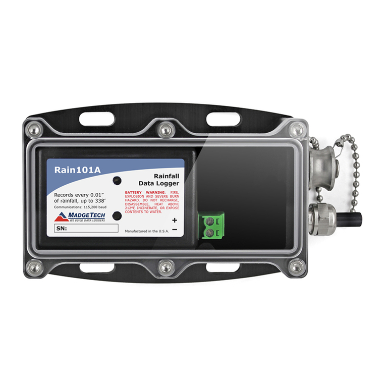
The State101A data logger monitors and records the
occurrence, duration and status of predetermined events
by measuring changes in voltage. Typically connected to
a relay or switch, this data logger features a removable
screw terminal block to easily disconnect and retrieve
the logger for data download without disrupting wiring
connectivity.
The State101A is a great solution for a variety of industries
and applications including HVAC studies to monitor
heating and cooling systems for efficiency or the
monitoring of gas, water or electric pumps. This device
replaces costly strip chart recorders and is also used in TTL
high/low monitoring, general status recording and security
systems as well.
Installation Guide
Installing the Interface Cable
IFC200 (sold separately) — Insert the device into a USB
port. The drivers will install automatically.
Installing the Software
The Software can be downloaded from the MadgeTech
website at madgetech.com. Follow the instructions
provided in the Installation Wizard. Compatible with
Standard Software version 2.03.06 or later and Secure
Software version 4.1.3.0 or later.
Wiring the Data Logger
Wiring Options
The State101A has a two-position removable screw
terminal connection. The State101A accepts 2-wire
configurations.
Warning: Note the polarity instructions. Do not attach wires
to the wrong terminals.
Device Operation
Connecting and Starting the Data Logger
1. Once the software is installed and running, plug the
interface cable into the data logger.
2. Connect the USB end of the interface cable into an
open USB port on the computer.
3. The device will appear in the Connected Devices list.
Highlight the desired data logger.
4. For most applications, select Custom Start from
the menu bar and choose the desired start method,
reading rate and other parameters appropriate for the
data logging application and click Start.
•Quick Start applies the most recent custom start
options
•Batch Start is used for managing multiple loggers
at once
•Real Time Start stores the dataset as it records
while connected to the logger
5. The status of the device will change to Running,
Waiting to Start or Waiting to Manual Start,
depending upon your start method.
6. Disconnect the data logger from the interface cable
and place it in the environment to measure.
Note: The device will stop recording data when the end of memory
is reached or the device is stopped. At this point the device cannot be
restarted until it has been re-armed by the computer.
Downloading Data from a Data Logger
1. Connect the logger to the interface cable.
2. Highlight the data logger in the Connected Devices list.
Click Stop on the menu bar.
3. Once the data logger is stopped, with the logger
highlighted, click Download. You will be prompted to
name your report.
4. Downloading will offload and save all the recorded
data to the PC.
