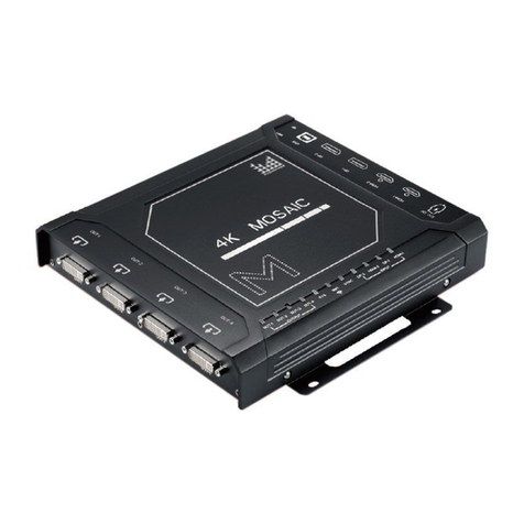
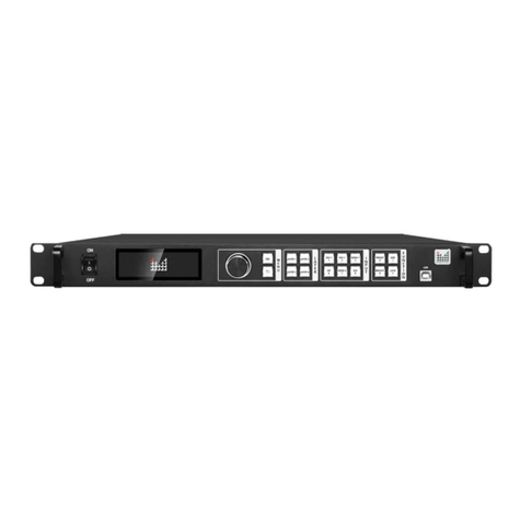
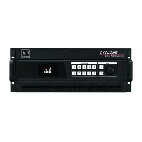
Magnimage MIG-680 User manual

MIG-680 Event Controller
User manual V1.0
△
!
All-in-one 4K Event Controller
Before using this video processor, please read this manual
carefully and keep it for reference in the future.

Without the written permission, any unit or individual could not
copy, reproduction or translate the book or part of it. Also could
not transmit it in any form or any way (electronic, mechanical,
photocopying, record or other way) for any business and profitable
purpose.
The product specifications and information mentioned in this
manual is just for reference, will not give prior notice if there is any
update. Unless there is a special agreement, it is just used as
guidelines. All the statements or information in this manual shall
not constitute any form of guarantee.
Statements

BRIEFS.................................................................................................................1
TRADEMARK CREDIT ................................................................................................................................ 1
ABOUT THE SOFTWARE............................................................................................................................. 1
FEATURES .............................................................................................................................................. 2
EXTENDED PORTS.................................................................................................................................... 3
SAFETY INSTRUCTIONS ............................................................................................................................. 4
SPECIFICATION........................................................................................................................................ 4
FUNCTION INTRODUCTION.................................................................................5
BRIEF.................................................................................................................................................... 5
THE FRONT PANEL ................................................................................................................................... 6
THE REAR PANEL ..................................................................................................................................... 7
Other.............................................................................................................................................. 9
TECHNICAL SPECIFICATIONS ..................................................................................................................... 10
USER MENU ......................................................................................................12
DEFAULT STATUS INTRODUCTION .............................................................................................................. 12
MAIN MENU INTRODUCTION................................................................................................................... 13
Main menu................................................................................................................................... 14
Picture setting.............................................................................................................................. 15
Output setting menu.................................................................................................................... 17
Input setting................................................................................................................................. 20
Layer setting................................................................................................................................. 23
Save and load............................................................................................................................... 29
EDID............................................................................................................................................. 33
Communication............................................................................................................................ 34
MISC............................................................................................................................................. 36
Language...................................................................................................................................... 40
MULTI-PREVIEW INTERFACE INTRODUCTION ............................................................................................... 41
BUTTON ............................................................................................................42
HOW TO USE THE BUTTON ...................................................................................................................... 42
MENU AREA:............................................................................................................................. 43
ADJUSTMENT area:................................................................................................................... 45
LAYER AREA:.............................................................................................................................. 46
LOGO AREA:.............................................................................................................................. 46
FUNCTION 1&2 AREA:............................................................................................................... 47
INPUT AREA:.............................................................................................................................. 49
PRESET AREA:............................................................................................................................ 50
TRANSITION AREA........................................................................................................................ 51
Directory

WARRANTY.......................................................................................................52
MACHINE WARRANTY ............................................................................................................................ 52
NON-WARRANTY .................................................................................................................................. 52

1
Briefs
Thanks for your purchasing our MIG-680 event controller. Do hope you can
enjoy the experience of the product performance. The design of the LED
video processor conforms to international and industry standards. But if with
improper operation, there will be a personal injury and property damage. In
order to avoid the danger, please obey the relevant instructions when you
install and operate the product.
Trademark credit
VESA is a Video Electronics Standards Association's trademark.
HDMI, HDMI mark and High-Definition Multimedia Interface are all from
HDMI.
Even if not specified company or product trademarks, trademark has been
fully recognized VESA is a Video Electronics Standards Association's
trademark.
About the software
Do not change, decompile, disassemble, decrypt or reverse engineer the
software installed in the product, these acts are illegal.

2
Features
1 Program output + 1 Multi-preview + 4 AUX outputs
4K×2K@60Hz Program output and AUX output
Customized input and output resolution
Support HDMI 2.0&DP 1.2 inputs
8 standard 4K×2K@60Hz input
Support expand 2 input modules,each one has 2 inputs
Extended board support DP1.2、HDMI2.0、SDI、DVI
Support HDCP1.4&2.2
4:4:4 processing technology
Internal multi-layer processing realize 4 layer to 4 layer seamless
switching
Support layer clip, crop and zoom
Support layer clone and shadow function
Support save & load up to 3 logos
Support layer mirror and shadow effect
Layer and Logo support chroma-key
Save & Load 20 user presets
Support touch screen, rotary knob control and T-BAR switch
Support Window & Mac software control
Support USB upgrade
Support the MIG-EXK200 keyboard when using PC control

3
Extended ports
The MIG-680 is the basic model. Based on this model, it can be extended
with 2 input modules,the extended modules are shown in the following
table:
Available extended module
Corresponding
model
Description
Input
Module
Expand 1 DP input module
MIG-680-P1
One DP input module includes 2 DP inputs
Expand 2 DP input modules
MIG-680-P2
One DP input module includes 2 DP inputs
Expand 1 HDMI input module
MIG-680-H1
One HDMI input module includes 2 HDMI inputs
Expand 2 HDMI input modules
MIG-680-H2
One HDMI input module includes 2 HDMI inputs
Expand 1 SDI input module
MIG-680-S1
One SDI input module includes 2 SDI inputs
Expand 2 SDI input modules
MIG-680-S2
One SDI input module includes 2 SDI inputs
Expand 1 DP and 1 HDMI input
modules
MIG-680-PH
One DP input module includes 2 DP inputs
One HDMI input module includes 2 HDMI inputs
Expand 1 DP and 1 SDI input
modules
MIG-680-PS
One DP input module includes 2 DP inputs
One SDI input module includes 2 SDI inputs
Expand 1 HDMI and 1 SDI input
modules
MIG-680-HS
One HDMI input module includes 2 HDMI inputs
One SDI input module includes 2 SDI inputs

4
Safety instructions
The power input voltage range of the product is 100~240V
AC/60HZ,please use the correct power supply accordingly.
When you need to connect or pull out any signal or control cables. Please
confirm that all the power supply cords have been pulled out ahead.
When you need to add hardware device for the machine, make sure all of
the signals and power cables have been pulled out ahead.
Before you operate any hardware, please turn off the MIG-680 event
controller’s power, release static electricity from your body by touching
the ground surface.
Please use the machine in clean, dry and ventilated environment, do not
use it in the high temperature or humidity environment.
The product is the electronic product; please stay away from the fire,
water and of which is inflammable and blast, dangerous.
This product is with high pressure components, please do not open the
case or repair the equipment by yourself.
As there is exceptional condition with smoke, ill-smelling, please turn off
the switch at once and contact with the dealers.
Specification
Specification
Input power supply
100~240VAC,50/60Hz
Power consumption
120W
Overall dimension(L×W×H)
539.6×182.2×492.8 Unit mm(L×W×H)
Net Weight
16.6Kg

5
Function introduction
Brief
MIG-680 is a 4K seamless switcher which combines input, output,
switching and controlling in one machine. Based on its 4K/60Hz 4:4:4
processing technology and matrix design, this switcher is able to manage and
switch 4K video freely.
MIG-680 is equipped with a touch screen, which supports fast menu
browsing and parameter adjustment the T-bar and the rotary knob can adjust
the parameters of the layer precisely. It is a indispensable event controller
with small size, powerful function and easy use in the video switching
domain .
There are abundant input and output ports:
Input:DP 1.2×4 and HDMI 2.0×4,supporting various extended input
modules and EDID function, such as DP1.2, HDMI2.0, 3G SDI and DVI.
Output:1 program output, 1 Multi-preview and 4 AUX output, each one
support 4096×2160@60Hz and customize the output resolution.
Support Window, Mac or Window withthe MIG-EXK200 keyboard control.

6
The front panel
Button instruction
1
MENU area
Include touch screen, the rotary knob, OK button and return button to adjust parameters and operate menu
2
ADJUSTMENT area
Include the rotary knob and buttons to adjust parameters
3
LAYER area
Choose and operate layer area
4
LOGO area
Choose and operate LOGO area
5
FUNCTION 1~2 area
Function area
6
INPUT area
Choose input signal area
7
PRSET area
Choose and operate preset area
8
TRANSITION area
Include T-bar and buttons to switch function setting
1
2
3
4
5
6
7
8

7
The rear panel
MIG-680 standard:
1- Program output
2- AUX output 1
3- AUX output 2
4- AUX output 3
5- AUX output 4
6- Standard input ports
7- Extended input slot 1
8- Extended input slot 2
9- Genlock input/output
10-USB: MIG-680 software upgrade
11-Internet access: connect PC
12-Multi-preview output ports
1
2
3
4
5
6
7
8
9
10
11
12

8
MIG-680-P2:
MIG-680-PS:
MIG-680-HS:
Remarks:the above is only the back of some models,please refer to
“extended ports”menu for all model names.

9
Other
The fan, power interface and switch

10
Technical specifications
Support 2 extended input modules, each one has 2 inputs.
Standard inputs
Port
Quantity
Resolution
HDMI 2.0 (1-4)
4
3840×2160/60Hz and EDID management
DP 1.2(5-8)
4
3840×2160/60Hz and EDID management
Extended input module
Port
Quantity
Resolution
DP1.2
DP×2
3840×2160/60Hz and EDID management
HDMI 2.0
HDMI×2
3840×2160/60Hz and EDID management
3G SDI
SDI×2
480i/60Hz、576i/50Hz、720p/60HZ、1080i/50Hz、1080i/60Hz、
1080P/60Hz(3G SDI)
DVI
DVI×2
1920×1080/60Hz and EDID management

11
Output
Port
Quantity
Resolution(single output)
Output(PROGRAM)
HDMI A-B
1×2
1920×1080/60Hz
4096×2160/60Hz
3840×2160/30Hz
1920×1080/50Hz
3840×2160/50Hz
1920×2160/60Hz
3840×1080/60Hz
3840×1280/60Hz
1920×1080/59.94Hz
3840×2400/60Hz
4096×2160/30Hz
1920×1200/60Hz
4096×2160/50Hz
3840×2160/60Hz
Output (AUX 1-4)
HDMI 1A-4A &1B-4B
4×2
Customized resolution(optimize):
Horizontal resolution up to 4352 pixels
Vertical resolution up to 2176 pixels
Output(PREVIEW)
HDMI & DVI
DVI×1
HDMI×1
1920×1080/60Hz
Remarks:4×2 indicates 4 groups of output and 2 duplicate output ports in
each group.
CONTROL interface
RJ45×1
RJ45 interface to control MIG-680
USB×1
USB port to upgrade MIG-680
GENLOCK IN×1 OUT×1
Genlock port to keep synchronization between multiple units
of MIG-680

12
User menu
Default status introduction
When turn on the power of MIG-680 event controller, the front panel of
the LCD screen will display the opening interface in system start-up procedure,
and the LCD screen will display the default status as below.
PROGRAM
540 OFF
540 OFF
960
960
0 0
960 0
Layer 1
Layer 2
None
None
540 OFF
540 OFF
960
960
0 540
960 540
Layer 3
Layer 4
None
None
PREVIEW
H Pos. V Pos. Width Height Clone Logo
Here is the guidance:
Window
Description
PROGRAM
Reveal the layer’s size, position and status of the PROGRAM in real time,
Notes:The PROGRAM frames will be not synchronous with the PREVIEW after openingTAKE
EDIT, but the PROGRAM output frames of the machine are synchronous with the PREVIEW
PREVIEW
Reveal the layer’s size, position and status of the PREVIEW operation in real time, the red
frame indicates the selected layer and the white frame indicates the layer that is not selected
Layer 1-4
The color lump status corresponds with the layer1-4 in the preview
H and V position
The corresponding H and V position of the layer
H width and V height
The corresponding H width and V height of the layer
Layer clone
The corresponding clone status of the layer,divided into off and on
Logo
The corresponding layer whether load the Logo,divided into:no, Logo1, Logo2, Logo3

13
Main menu introduction
The symbols listed in the below table will appear in the main menu,the
specific meanings are as follows:
In the main menu, the user selects and adjusts each item by using the three
buttons “OK”, “ ” and the knob or by touching the corresponding menu.
The operation mode is as follows:
Icon
Explanation
Return to the main menu or return to the previous menu
Operation
Button
Open the main menu
Press the "OK" button or press the“knob”by default
Selected each item
Rotate the knob to select each item or touch click on the corresponding
menu
Adjust parameters
When the right end of the item is a number or option parameter, press the
“knob”to select the parameter, or touch click ”” ” to adjust
the parameter to be small or large, or touch the parameter and click in the
pop-up numeric key input area. Parameter adjustment
Enter the next menu
When the right end of the item is the “ ” symbol, press the “OK”
button or press the knob or touch to click the menu.
Process some function
Use the knob to select the item to be executed, press the "OK" button or
touch to click the function.
Return to the previous
menu
Press the " " button or touch the return icon
Confirm operation
In order to avoid wrong operation in reset operation, it is necessary to
confirm operation or touch click with "OK" key.
Menu button appear to
yellow box
Indicate knob selected,could move to next operation
Function menu word is
yellow
Indicate this function menu is occupied
Function menu word is
white
Indicate this function menu is not occupied

14
Numeric keypad description: in addition to any parameters that need to
be modified, except press and rotate the knob, touch the left and right
arrow keys to operate, it also clicks the corresponding parameter and
pops up the numeric keypad on the screen to operate.And 0 to 9
represent numbers,
indicating a decimal point,
means to exit the numeric keypad mod,
indicating confirmation of the modified parameters
Represents a backspace to delete the entered number.
The numeric keypad is shown below.
Main menu
In the default state, press“OK”or“Knob”to enter the main menu, and the
LCD screen will show the details as below:
The main menu has nine sub menu items. Rotating the knob”to select the
above listed nine sub menu title, the selected menu icon font color is yellow,
selected, press “OK”button to enter the selected project, press ” ”to be
back. Or touch the LCD screen enter correspond sub menu.
PICTURE OUTPUT INPUT
LANGUAGE/语言
EDID
LAYERS
COMMUUNICATION
SAVE/LOAD
MISC
3840
1 2 3
4 5 6
7 8 9
0 .
COK <-

15
Picture setting
Bright LVL
PICTURE Page:1/2
OFF
Gamma
Layer1 Picture Setting
Layer2 Picture Setting
Layer3 Picture Setting
OFF
PICTURE Page:2/2
Layer4 Picture Setting
Reset Picture Setting Cancel
Reset
Layer 1-4 picture setting:
Brightness
PICTURE
50
Color Temp
Reset
Contrast 50
Saturation 50
Cancel
Reset
Layer1 Picture Setting

16
Layer 1-4 color temperature setting:
Color Temp
Color temp
6500K
Reset
R 128
G 128
Cancel
Reset
Layer 1
B 128
Note: Arrow points to the menu that pops up for this option.
Image setting sub menu is used to set this device output layer’s brightness level, Gamma value
and the parameter for each layer.
Brightness level
Open or close this function, range from 0 to 16.
Gamma
Open or close this function, gamma range from 0.0 to 5.0.
Layer 1~4 picture
setting
Brightness: range 0~100, the default is 50
Contrast: range 0~100, the default is 50.
Saturation: range 1~100, the default is 50.
Layer 1~4
color
temperature
setting
Divided into “4000K”, “5000K”, “6500”,
“7500K”, ”8200K”, ”9300K”, “10000K”,
“11500K”, “User”, total 9 options.
Red range 0~225, the default is 128.
Green range 0~225, the default is 128.
Blue range 0~225, the default is 128.
Layer 1~4 picture
setting
Reset all the layers’picture parameters to default setting.
Table of contents
Other Magnimage Controllers manuals
Popular Controllers manuals by other brands

Linear Technology
Linear Technology LTC3805/-5 quick start guide

Hubbell
Hubbell CHANCE BPRS Installation, operation and maintenance manual

YASKAWA
YASKAWA SI-ES3 installation manual

Leviton
Leviton D8000 installation instructions

Beckhoff
Beckhoff CU8890-0000 Installation and operating instructions

Love Controls
Love Controls 2600 SERIES instructions

VALPES
VALPES ER35 Installation and operation manual

Orion
Orion vortex R10 instruction manual

ESBE
ESBE 98140201 manual

ICI Caldaie
ICI Caldaie ICI Kronos INSTRUCTIONS FOR USER, INSTALLER AND TECHNICAL SERVICE CENTRE

Mitsubishi
Mitsubishi D700 VFD installation guide

Bard
Bard CompleteStat CS9B-THOA Installation and operation guide