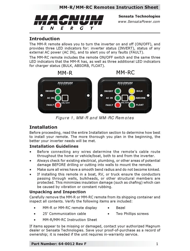
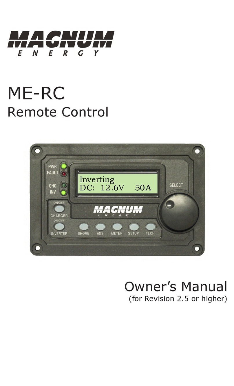
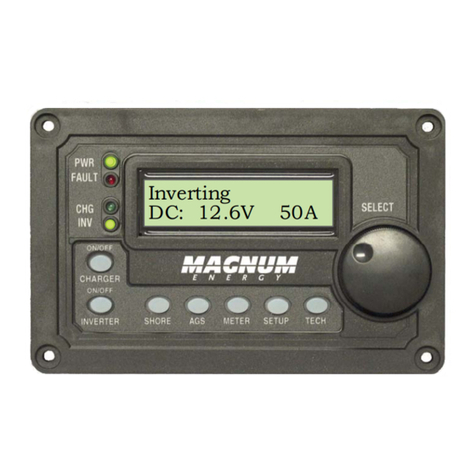
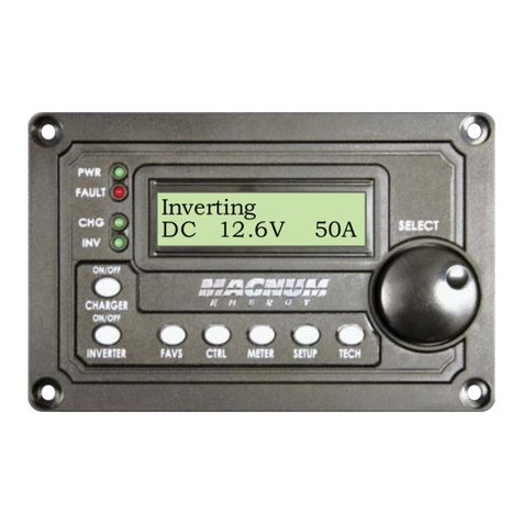
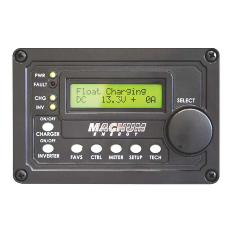
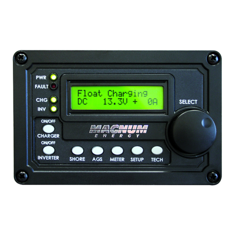
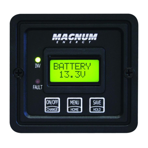
Magnum Energy ME-ARC Series User manual

Owner’s Manual
(for Revision 3.0 or higher)
ME-ARC
Advanced Remote Control

i © 2012 Magnum Energy, Inc.
Disclaimer of Liability
Since the use of this manual and the conditions or methods of installation,
operation, use and maintenance of the ME-ARC is beyond the control of
Magnum Energy, Inc., this company does not assume responsibility and
expressly disclaims liability for loss, damage or expense, whether direct,
indirect, consequential or incidental, arising out of or in any way connected
with such installation, operation, use, or maintenance.
Note as well that while every precaution has been taken to ensure the
accuracy of the contents of this manual, the specifications and product
functionality may change without notice. Magnum Energy, Inc. assumes no
responsibility for errors or omissions.
Restrictions on Use
The ME-ARC remote may only be used in life-support devices or systems
with the express written approval of Magnum Energy. Failure of the ME-ARC
remote can reasonably be expected to cause the failure of that life-support
device or system, or to affect the safety or effectiveness of that device or
system. If the ME-ARC remote fails, it is reasonable to assume that the
health of the user or other persons may be endangered.
Copyright Notice
Copyright © 2012 by Magnum Energy, Inc. All rights reserved. Permission to
copy, distribute, and/or modify this document is prohibited without express
written permission by Magnum Energy, Inc.
Document Information
Description – ME-ARC Owner’s Manual
Part Number and Revision – 64-0030 Rev B
Date Published – June 2012
This manual is printed without color for cost savings. However, this entire
manual is available for download under the Document Library tab at
www.magnumenergy.com with many of the figures available in color.
Contact Information
Magnum Energy, Inc.
2211 West Casino Rd.
Everett, WA 98204
Phone: 425-353-8833
Fax: 425-353-8390
Web: http://www.magnumenergy.com
Statement of Appreciation
From all of us at Magnum Energy –
Thank you for purchasing this ME-ARC remote.
We understand that you have many purchasing options in the marketplace,
and are pleased that you have decided on a Magnum Energy product. This
ARC remote was proudly assembled and tested in the United States in our
Everett, Washington, facility.
At Magnum we are committed to providing you with quality products and
services, and hope that your experience with us is pleasant and professional.
Magnum Energy® is a registered trademark of Magnum Energy, Inc.

© 2012 Magnum Energy, Inc. ii
Important Product Safety Instructions
This manual contains safety instructions that must be followed during the
installation and operation of this product. Read all instructions and safety
information contained in this manual before installing or using this product.
Safety Symbols
To reduce the risk of electrical shock, fire, or other safety hazard, the
following safety symbols have been placed throughout this manual to
indicate dangerous and important safety instructions.
WARNING: Indicates that failure to take a specified action could
result in physical harm to the user.
CAUTION: Indicates that failure to take a specified action could
result in damage to the equipment.
Info: Indicates information that emphasizes or supplements im-
portant points of the main text.
Remedy: Provides possible solutions for related issues.
Product Safety Alerts
All electrical work must be performed in accordance with local, state, and
federal electrical codes.
WARNINGS:
• All electrical work must be performed in accordance with local,
state and federal electric codes.
• This product is designed for indoor/compartment installation.
It must not be exposed to rain, snow, moisture, or liquids of
any type.
• Use insulated tools to reduce the chance of electrical shock or
accidental short circuits.
• Remove all jewelry such as rings, watches, bracelets, etc., when
installing or performing maintenance on the inverter.
• Always disconnect the batteries or energy source prior to in-
stalling or performing maintenance on the inverter. Live power
may be present at more than one point since an inverter uti-
lizes both batteries and AC. Turning off the inverter may not
reduce this risk on some Magnum inverters. As long as AC
power is connected, it will pass thru the inverter regardless
of the power switch on the inverter or the ON/OFF INVERTER
button on the remote.

iii © 2012 Magnum Energy, Inc.
Table of Contents
1.0 Overview.................................................................................. 1
2.0 Installation............................................................................... 2
2.1 Pre-Installation......................................................................... 2
2.1.1 Installation Guidelines ......................................................... 2
2.1.2 Unpacking and Inspection .................................................... 2
2.1.3 Tools Required .................................................................... 2
2.2 Connecting the Remote Cable ..................................................... 3
2.2.1 Connecting the ME-ARC to a Magnum Inverter ........................ 3
2.3 ME-ARC Remote and Bezel Dimensions ........................................ 4
2.4 Mounting the ME-ARC Remote .................................................... 5
2.4.1 Flush Mount Installation Procedure ........................................ 5
2.4.2 Surface Mount Installation Procedure ..................................... 6
2.5 Power-up Self Test .................................................................... 7
3.0 Setup........................................................................................ 8
3.1 Navigating the Remote .............................................................. 8
3.2 Remote Feature to Inverter Compatibility ................................... 10
3.3 Remote Buttons and Menu Items .............................................. 14
3.3.1 FAVS Button and Menus ..................................................... 14
3.3.2 CTRL (Control) Button and Menus........................................ 16
CTRL: 01 ACIn Control............................................................ 17
CTRL: 02 CHG (Charge) Control ............................................... 18
CTRL: 03 Gen Control ............................................................. 18
3.3.3 METER Button and Menus................................................... 19
METER: 01 DC Meters ............................................................. 20
METER: 02 AC Meters ............................................................. 20
METER: 03 AGS Meters ........................................................... 21
METER: 04 BMK Meters........................................................... 21
3.3.4 SETUP Button and Menus ................................................... 21
SETUP: 01 Remote Setup ........................................................ 22
SETUP: 02 Invert Setup .......................................................... 23
SETUP: 03 Charger Setup........................................................ 28
SETUP: 04 AGS Setup............................................................. 37
SETUP: 05 BMK Setup ............................................................ 37
3.3.5 TECH Button and Menus..................................................... 38
TECH: 01 Temperatures .......................................................... 38
TECH: 02 Revisions ................................................................ 39
TECH: 03 Inv Model................................................................ 39
TECH: 04 Fault History............................................................ 39
TECH: 05 SETUP PIN .............................................................. 41
TECH: 06 Ext Control.............................................................. 42
TECH: 07 Load Defaults .......................................................... 43
4.0 Menu Maps: ME-ARC Remote Control...................................... 44
5.0 Operation ............................................................................... 49
5.1 Front Panel ............................................................................ 49
5.1.1 LED Indicators .................................................................. 49
5.1.2 LCD Display...................................................................... 49
5.1.3 ON/OFF Pushbuttons ......................................................... 50
5.1.4 Menu Buttons ................................................................... 50
5.1.5 Rotary SELECT Knob.......................................................... 50

© 2012 Magnum Energy, Inc. iv
Table of Contents (cont.)
5.2 Operating the Inverter/Charger................................................. 51
5.2.1 Inverter Mode................................................................... 51
5.2.2 Charger Mode................................................................... 51
5.3 System Status Messages.......................................................... 52
5.3.1 Inverter Mode Status Messages........................................... 52
5.3.2 Charger Mode Messages..................................................... 53
5.3.3 Secondary Scrolling Status Messages................................... 56
5.3.4 Fault Mode Messages ......................................................... 56
5.3.4.1 System Fault Messages ............................................... 56
5.3.4.2 Stacking Fault Messages............................................... 59
5.3.4.3 Internal Fault Messages ............................................... 60
5.3.5 LED Indicator Guide .......................................................... 61
6.0 Troubleshooting ..................................................................... 62
6.1 Troubleshooting Tips................................................................ 63
6.1.1 Inverter Problems ............................................................. 63
6.1.2 Charger Problems ............................................................. 63
6.2 Performing an Inverter Reset.................................................... 64
6.3 Performing a Power Reset ........................................................ 64
7.0 Using a ME-AGS-N Module ...................................................... 65
7.1 ME-AGS-N Setup..................................................................... 65
7.2 ME-AGS-N Functional Tests ...................................................... 76
7.2.1 Remote to Generator Communications Test........................... 76
7.2.1.1 Determining AGS Statuses............................................ 76
7.2.1.2 Starting the Generator from the Remote......................... 77
7.3 ME-AGS-N Operation/Monitoring ............................................... 77
7.3.1 Controlling the AGS ........................................................... 77
7.3.2 Monitoring the AGS ........................................................... 78
7.3.2.1 ME-ARC Remote’s AGS METER Button ............................ 78
7.3.2.2 ME-ARC Remote’s AGS TECH Button .............................. 80
7.4 Enabling the ME-AGS-N ........................................................... 81
7.5 Starting and Stopping the Generator ......................................... 81
7.6 ME-AGS-N Menu Map Using the ME-ARC..................................... 83
7.7 ME-AGS-N Remote Status Messages .......................................... 86
7.7.1 AGS Remote Operational Statuses ....................................... 86
7.7.2 AGS Remote Start Statuses ................................................ 87
7.7.3 AGS Remote Fault Statuses ................................................ 88
7.7.4 AGS Notes ....................................................................... 89
7.8 ME-AGS-N Remote Troubleshooting ........................................... 90
7.8.1 AGS Fault Message Screen ................................................. 90
7.8.2 Resolving Operational Statuses ........................................... 90
7.8.3 Resolving AGS Faults Using the Remote ............................... 91
7.8.4 How to Clear AGS Faults .................................................... 93
7.8.5 How to Clear AGS Fault History ........................................... 93
8.0 Using a ME-BMK ..................................................................... 94
8.1 Setting Up the BMK ................................................................. 94
8.2 Monitoring the BMK................................................................. 95
8.3 ME-ARC Remote’s BMK Menu Maps............................................ 98
9.0 Limited Warranty ................................................................... 99
9.1 How to Receive Repair Service ................................................ 100

v © 2012 Magnum Energy, Inc.
List of Tables
Table 3-1, ME-ARC Compatibility Matrix ......................................... 10-13
Table 3-2, Battery Type to Charge Voltages ......................................... 31
Table 3-3, Battery Amp/Hrs Capacity to Suggested Absorb Time ............ 34
Table 3-4, Inverter/Charger Default Settings on ME-ARC....................... 43
Table 5-1, LED Indicator Guide .......................................................... 61
Table 6-1, Remote Control Troubleshooting Guide ................................ 62
Table 7-1, ME-ARC Autostart/Autostop Matrix ...................................... 65
Table 7-2, AGS Remote Operational Statuses.................................. 86-87
Table 7-3, AGS Remote Start Statuses................................................ 87
Table 7-4, AGS Remote Fault Statuses................................................ 88
Table 7-5, AGS Default Settings on ME-ARC ........................................ 88
Table 8-1, BMK Default Settings on ME-ARC ........................................ 97
List of Figures
Figure 1-1, Front Panel Features.......................................................... 1
Figure 2-1, Remote Cable ................................................................... 3
Figure 2-2, Remote Control Connections ............................................... 3
Figure 2-3, ME-ARC Remote Dimensions............................................... 4
Figure 2-4, Remote Bezel Dimensions .................................................. 4
Figure 2-5, Flush Mounting the ME-ARC ................................................ 5
Figure 2-6, Surface Mounting the ME-ARC using the Bezel....................... 6
Figure 2-7, Power-up Self Test Screens................................................. 7
Figure 2-8, Self Test Set Clock Screens................................................. 7
Figure 3-1, Front Panel Setup Features................................................. 8
Figure 3-2, SETUP Menu Navigation ..................................................... 9
Figure 3-3, FAVS Button and Menus ................................................... 15
Figure 3-4, CTRL Button and Menus ................................................... 16
Figure 3-5, METER Button and Menus................................................. 20
Figure 3-6, SETUP Button and Menus ................................................. 22
Figure 3-7, TECH Button and Menus................................................... 38
Figure 3-8, Inverter Fault History Menu Items ..................................... 40
Figure 4-1, FAVS/CTRL/METER Button Menu Maps................................ 44
Figure 4-2, SETUP Button Menu Map .................................................. 45
Figure 4-3, SETUP Button Menu Map .................................................. 46
Figure 4-4, SETUP/TECH Button Menu Maps ........................................ 47
Figure 4-5, TECH Button Menu Map.................................................... 48
Figure 5-1, ME-ARC Front Panel Controls and Indicators........................ 49
Figure 5-2, System Status Screen (example)....................................... 52
Figure 6-1, Performing an Inverter Reset ............................................ 64
Figure 7-1, AGS Fault History Menu Items........................................... 80
Figure 7-2, ME-AGS-N Menu Maps using ARC Remote (Section 1) .......... 83
Figure 7-3, ME-AGS-N Menu Maps using ARC Remote (Section 2) .......... 84
Figure 7-4, ME-AGS-N Menu Maps using ARC Remote (Section 3) .......... 85
Figure 7-5, ME-AGS-N Fault Message (Example) .................................. 90
Figure 8-1, ME-BMK Menu Map using ARC Remote ............................... 98
© 2012 Magnum Energy, Inc. 1
1.0 Overview
1.0 Overview
The ME-ARC remote control allows you to monitor and customize the
operating parameters for your Magnum inverter/charger. This remote can be
used on all Magnum inverter/charger models so there is no cross-platform
confusion.
The ME-ARC50 comes standard with a 50-foot, 4-conductor (twisted-pair)
telephone cable and includes non-volatile memory (preserves adjustable
settings, even if power to the remote or inverter is removed).
Info: This manual is for the ME-ARC with revision 3.0 or higher;
see the TECH: 02 Revisions section on page 39 for information on
how to determine your revision level.
The ME-ARC is equipped with the following features:
• LED Indicators – The at-a-glance LEDs provide the inverter/charger
status in a straightforward way.
• LCD Display – The LCD display is a 16 x 2 line (32 characters total)
alphanumeric display used for setting up the inverter/charger operation,
as well as viewing current status or fault messages.
• ON/OFF Pushbuttons (x2) – The ON/OFF pushbuttons allow the inverter
or charger to be independently and quickly enabled or disabled.
• Menu Buttons (x5) – Allow the inverter or charger to be configured to
your specific system preferences. These buttons also allow simple access
to menu items that can help with monitoring and troubleshooting your
inverter/charger system.
• Rotary SELECT Knob – The rotary encoder knob is similar to a car dash
radio knob and is used to quickly scroll through and select various menu
items and settings. Pushing the rotary knob allows you to select a menu
item, or to save a setting once it is displayed on the LCD.
Menu Buttons Rotary SELECT Knob
LCD
Display
ON/OFF
Pushbuttons
LED
Indicators
Figure 1-1, Front Panel Features

2 © 2012 Magnum Energy, Inc.
2.0 Installation
2.0 Installation
Review this section and the Important Product Safety Instructions on the
front inside cover before proceeding with the installation of your remote.
WARNING: Installations should be performed by qualified per-
sonnel, such as a licensed or certified electrician. The installer
determines which safety codes apply and ensures all applicable
installation requirements are followed. Applicable installation codes
vary depending on the specific location and application.
CAUTION: When connecting battery power to the inverter, all
battery negative connections must be connected prior to the bat-
tery positive connections. When removing battery power from the
inverter, the battery positive should be removed before any battery
negative connections are disconnected. This prevents any communi-
cation chips/lines from becoming the DC return path to the battery—
causing permanent damage to all connected accessories.
Summation: Ensure all battery negative circuits are always con-
nected before connecting or disconnecting battery positive.
2.1 Pre-Installation
Before proceeding, read the entire Installation section to determine how
best to install your ME-ARC remote. The more thorough you plan in the
beginning, the better your inverter needs will be met.
2.1.1 Installation Guidelines
• Before connecting any wires determine the remote’s cable route through-
out the home or vehicle/boat, both to and from the inverter.
• Always check for existing electrical, plumbing, or other areas of potential
damage BEFORE drilling or cutting into walls to mount the remote.
• Make sure all wires have a smooth bend radius and do not become kinked.
• If installing this remote in a boat, RV, or truck ensure the conductors
passing through walls, bulkheads, or other structural members are pro-
tected. This minimizes insulation damage (such as chafing) which can
be caused by vibration or constant rubbing.
2.1.2 Unpacking and Inspection
Carefully remove the ME-ARC remote from its shipping container and inspect
all contents. Verify the following items are included:
• The ME-ARC remote display
• Bezel
• 50’ remote cable
• Eight #8 x 3/4 Phillips screws
• ME-ARC owner’s manual
If items appear to be missing or damaged, contact your authorized Magnum
Energy dealer or Magnum Energy. Save your proof-of-purchase as a record
of your ownership; it is needed if the unit should require in-warranty service.
2.1.3 Tools Required
Installing the remote control is simple and requires the following tools:
• Phillips screwdriver • Level • Drill
• Cut-out tool (knife/saw) • Pencil • Drill bit (7/64”)

© 2012 Magnum Energy, Inc. 3
2.0 Installation
2.2 Connecting the Remote Cable
The ME-ARC comes with a remote cable to enable communication between the
inverter and the remote. The remote cable is a 50-foot, 4-conductor, round,
telephony standard with 6P4C (6-position/4-conductor) connectors on each
end. When the 6P4C connectors are held side by side with both of the connec-
tor tabs facing the same way, the color of the conductors in each connector
is the opposite from top to bottom (as shown in Figure 2-1).
Note: The remote cable can be extended up to a length of 200 feet without
data degradation.
12341234
TAB
TAB
same color
same
color
4-conductor
telephone-type
opposite col-
ors from top to
bottom (tabs fac-
ing toward you)
Figure 2-1, Remote Cable
2.2.1 Connecting the ME-ARC to a Magnum Inverter
One end of the remote cable plugs into the back side of the ME-ARC, and the
other plugs into the REMOTE (blue) port on the Magnum inverter/charger
(see Figure 2-2).
Note: Do not connect the remote cable at this time. First, locate and prepare
an area to mount the remote (follow directions in Section 2.4).
Large Magnum inverter
ME-ARC
Remote
(back)
Small Magnum inverter
ME-ARC
remote
(back)
Figure 2-2, Remote Control Connections

4 © 2012 Magnum Energy, Inc.
2.0 Installation
5 ¼” (13.3 cm)
3 ¼” (8.3 cm)
5 ⅞" (14.9 cm)
3 ⅞" (9.8 cm)
.9"
(2.3 cm)
1 ⅛”
(2.9 cm)
1 ½”
~1"
(2.5 cm)
2 ¾”
(7.0 cm)
~1⅝"
(4.1 cm)
Figure 2-4, Remote Bezel Dimensions
Figure 2-3, ME-ARC Remote Dimensions
~1½" (3.8 cm)
3⅞" (9.8 cm)
4⅜" (11.1 cm)
5¼" (13.3 cm)
5⅞" (14.9 cm)
2⅞" (7.3 cm)
3¼" (8.3 cm)
4⅜" (11.1 cm)
2⅞" (7.3 cm)
Cut out tab to
run remote cable
flush to surface
2.3 ME-ARC Remote and Bezel Dimensions
Use the information below (Figures 2-3 and 2-4) in preparation for mounting
the ME-ARC remote and the bezel (if applicable). Directions for mounting
both follow in Section 2.4.

© 2012 Magnum Energy, Inc. 5
2.0 Installation
2.4 Mounting the ME-ARC Remote
The ME-ARC can either be flush mounted (through an opening in the wall),
or surface mounted using the provided bezel. Find a location that is clean,
dry and protected. Allow room to access the remote’s SELECT knob and to
view the LEDs/display.
CAUTION: Ensure that no AC power is connected to the inverter,
and then according the your inverter owner’s manual correctly con-
nect the inverter to the batteries.
CAUTION: Always check for hidden electrical wires, pipes and cables
BEFORE drilling, cutting, or screwing into walls or cabinets.
2.4.1 Flush Mount Installation Procedure
To flush mount, the wall opening must have at least a 2” (5 cm) depth to
allow room for the remote and the cable.
1. Cut an opening in the wall (Figure 2-5). Ensure there are no openings
around the display and enough material for the screws to secure the unit.
2. Drill four pilot holes for the #8-32 screws that will attach the remote to
the wall (refer to Figure 2-3 for hole locations and dimensions).
3. Route one end of the cable through the wall cutout to the inverter/charger,
and then plug it into the RJ11 REMOTE port (blue label) on the inverter/
charger—inverter has DC power, but is OFF. See Figure 2-2.
4. Take the other end of the remote cable and while plugging it into the
back of the ME-ARC, view the remote’s display to ensure the Power-up
Self Test initiates (see Section 2.5).
5. If the self test is successful, secure the ME-ARC to the wall using four of
the supplied Phillips screws. If the self test is unsuccessful, refer to the
Troubleshooting section.
Figure 2-5, Flush Mounting the ME-ARC
3.0"
(7.6 cm)
5.0"
(12.7 cm)

6 © 2012 Magnum Energy, Inc.
2.0 Installation
2.4.2 Surface Mount Installation Procedure
To surface mount, you must use the supplied bezel (Figure 2-4).
Info: The bezel has tabs at the bottom and side that are made with
thinner material (Figure 2-4). They can be cut or broken out to allow
the cable to be routed downward or to the side (Figure 2-6).
1. Using the bezel as a template, mark on the wall the location of the four
bezel mounting screws, and then drill pilot holes for the #8-32 screws.
2. Cut/break the appropriate tab for the planned route of the remote cable.
3. Pull the cable thru the bezel and place the bezel side with the removed
tab over the cable against the wall.
4. Position the bezel over the drilled mounting holes, and then screw the
bezel to the wall using the supplied Phillips screws (Figure 2-6).
5. Route the other end of the cable to the inverter/charger, and then plug
it into the inverter’s RJ11 REMOTE port (blue label)— inverter has DC
power, but is OFF. See Figure 2-2.
6. Take the other end of the cable and while plugging it into the back of
the ME-ARC, view the remote’s display to ensure the Power-up Self Test
initiates (see Section 2.5).
7. If the self test is successful, secure the ME-ARC to the bezel using four
of the supplied Phillips screws. If the self test is unsuccessful, refer to
the Section 6.0 “Troubleshooting”.
Figure 2-6, Surface Mounting the ME-ARC using the Bezel

© 2012 Magnum Energy, Inc. 7
2.0 Installation
2.5 Power-up Self Test
Info: All power to operate the remote control is provided by the
inverter/charger through the remote cable.
When the ME-ARC is first connected to an inverter, a power-up self test is
initialized. During the self test, the LCD automatically displays in sequence:
• “MAGNUM ENERGY Self Test”, then
• “(C) 2010-2012, Connecting to...”, and then
• “ME-ARC V 3.0, INV/CHG V #.#”
The remote’s LEDs also change with the screens (see Figure 2-7).
FAULT
PWR
CHG
INV
MAGNUM ENERGY
Self Test
FAULT
PWR
CHG
INV
(C)2010-2012
Connecting to..
FAULT
PWR
CHG
INV
ME-ARC V 3.0
INV/CHG V #.#
No LEDs light
PWR lights green
FAULT lights red
CHG lights green
INV lights green
CHG lights green
INV lights green
After the self test is finished the remote displays “Set Clock”.Use the ME-ARC’s
SELECT knob to set the correct time by selecting hour, minutes, and either
AM or PM (See Figure 2-8 below, and the Set Clock procedure on page 22).
Figure 2-7, Power-up Self Test Screens
Set Clock
AM-PM = 12:00A
Set Clock
Minute = 12:12A
Set Clock
Hour = 12:00A
Figure 2-8, Self Test Set Clock Screens

8 © 2012 Magnum Energy, Inc.
3.0 Setup
3.0 Setup
When the remote is connected to a Magnum inverter/charger, the settings in
the remote control determine the inverter/charger’s operating parameters.
The default settings in the remote control are adequate for most installations
(see Table 3-4); however, you have the option to change some of the
operating parameters. This section shows you how to navigate the remote
and gives you an understanding of the function of each adjustable setting.
3.1 Navigating the Remote
The ME-ARC has menu items and adjustable settings that provide the ability
to configure your inverter/charger to your specific parameters.
Info: See Figures 4-1 through 4-5 for complete maps of the inverter/
charger’s menu items and adjustable settings.
Familiarize yourself with the display and controls on the remote’s front panel
that are used to find, adjust, and save the desired settings (see Figure 3-1).
• LCD Display –The 2-line LCD display shows status and information for
the inverter/charger and any attached accessories. All setup menus and
faults also appear on the LCD display.
Info: The LCD display returns to the remote home screen to show
DC voltage and current (see Figure 3-1) after five minutes if no
buttons have been pressed.
Info: When the ←(left facing arrow) symbol is shown on the display,
the displayed setting has been selected and will be used.
• Menu Buttons (x5) –These five buttons allow simple access to menu
items that can help with configuring, monitoring, and troubleshooting
your inverter/charger system.
• Rotary SELECT Knob –This rotary knob allows you to quickly scroll
through and select various menu items and settings. Pressing the knob
selects the menu item to change, or saves the current selection.
Info: Hold down the SELECT knob for 10 seconds to refresh the LCD
display.
Rotary
SELECT Knob
LCD
Display
Menu
Buttons
Figure 3-1, Front Panel Setup Features

© 2012 Magnum Energy, Inc. 9
3.0 Setup
Figure 3-2, SETUP Menu Navigation
4. Press the SELECT knob to
change the desired setting.
Top line shows menu item.
Bottom line shows current setting.*
Rotate the SELECT knob to the
desired setting.
When the bottom line shows the
desired setting:
5. Press the SELECT knob to
save this setting.
3. Press the SELECT knob.
When the bottom line shows the
desired menu heading:
1. Press the SETUP menu button.
Bottom line shows a menu
heading.
2. Turn the SELECT knob to the
desired menu heading.
*[If this setting is correct, rotate
the SELECT knob to continue to
the next menu item.]

10 © 2012 Magnum Energy, Inc.
3.0 Setup
3.2 Remote Feature to Inverter Compatibility
The ME-ARC has many settings and is designed to work with the advanced
features in your Magnum inverter—and/or other Magnum devices (i.e., ME-
AGS-N or ME-BMK). The ME-ARC communicates with your inverter to allow the
set up and enabling of these advanced features. However, when the ME-ARC
is released with new software, some of the features and functionality in the
remote may not be available in an inverter or networked accessory that has
an earlier software level. In this case, the advanced setting is not recognized
and will not function. Use the steps below to help you determine which ME-
ARC (Revision 3.0) menus/features are compatible with your inverter.
1. Go to: http://www.magnumenergy.com/Service/Compatibility.htm to
determine your inverter’s compatibility level (L1, L2, L3 or L4).
2. Use Table 3-1 to determine which ME-ARC ‘features/settings’ you want
to use and what inverter compatibility level is required (see the “Model/
Level Required” column in Table 3-1).
3. If your inverter compatibility level is the same or greater than the level
required, your inverter can support the device setting/feature you want.
4. If your inverter does not have the required compatibility level for a fea-
ture/setting you want, contact Magnum Energy for a software upgrade.
Info: This compatibility matrix is available online to download/
print as a single page document and to enter user settings.
http://www.magnumenergy.com/Service/Compatibility.htm.
Table 3-1, ME-ARC (Revision 3.0) Compatibility Matrix
Button
FEATURES/SETTINGS Model/
Level
Required
Default
Setting
Main
Menu Menu
Heading/Item Selections/
Adjustments Range
CTRL
01 ACIn Control
Auto Connect ≥Level 1
Auto
Connect
VDC Connect, Time
Connect, AC-In Disabled
≥Level 3
[1]
SOC Connect ≥Level 3 [1][6]
02 CHG Control [5] Multi-Stage, Force
Float, Restart Bulk
≥Level 4 Multi-
Stage
03 Gen Control OFF, ON, AUTO ≥Level 1 [7] OFF**
METER
01 DC
Meters
01A DC Volts
Read only display ≥Level 1 Read
Only
01B DC Amps
01C Charge
Time
02 AC
Meters
[5]
02A Output Volts
Read only display
≥Level 4
Read
Only
02B Output Hz
02C Load Amps
≥Level 4 [1, 3]
02D Input Amps
02E Inv/Chg
Amps
02F Input AC
(AC1)
02G Input AC2 MSH-RE Models

© 2012 Magnum Energy, Inc. 11
3.0 Setup
Table 3-1, ME-ARC Compatibility Matrix (cont.)
Button
FEATURES/SETTINGS Model/
Level
Required
Default
Setting
Main
Menu Menu
Heading/Item
Selections/
Adjustments
Range
METER
03
AGS
Meters
03A AGS Status
Read only display ≥Level 1 Read Only
03B DC Volts-AGS
03C Gen Run Time
03D AGS Temp
03E Since GenRun
04
BMK
Meters
04A BMK Status
Read only display ≥Level 1 Read Only
04B SOC
04C DC Volts-BMK
04D DC Amps-BMK
04E AH in/Out
04F Reset AH Out
04G Total AH Out
04H Minimum
VDC
04I Maximum VDC
SETUP
01 Re-
mote
Setup
01A Set Clock Time= 12:00A-
12:00P
≥Level 1
12:00A**
01B Contrast 0-100% 100%**
01C Backlight 0-100% 50%**
01D Power Save OFF, 1-60 Minutes 15 Minute
01E Temp Display Fahrenheit, Celsius Fahrenheit
02
Invert
Setup
02A Search Watts OFF, 5-50 Watts
(1-Watt increments)
≥Level 1 5 Watts
02B LBCO
Setting
9.0-12.2*VDC ≥Level 2 10.0 VDC
02C AC In - Time Connect Time=
12:00A-12:00P
≥Level 3
[1]
6:00A
6:00P
Disconnect Time=
12:00A-12:00P
02D AC In - VDC Connect Volts=
9.0-15.9*(12V)
≥Level 3
[1]
11.0
Disconnect Volts=
9.0-15.9*(12V)
14.1

12 © 2012 Magnum Energy, Inc.
3.0 Setup
Table 3-1, ME-ARC Compatibility Matrix (cont.)
Button
FEATURES/SETTINGS Model/
Level
Required
Default
Setting
Main
Menu
Menu
Heading/
Item
Selections/
Adjustments Range
SETUP
02
Invert
Setup
(cont.)
02E AC-In
SOC
Connect SOC= 20-98% ≥Level 3
[6]
50%
Disconnect SOC= 21-100%
100%
02F Power Up
Always ON, OFF ≥Level 1 Always
OFF
03
Char-
ger
Setup
03A AC Input
Amps
AC/AC1 Input= 5-60A ≥Level 1 [1] 30A
AC2 Input= 5-60A MSH-RE Models 20A
03B Battery
Type
Gel, Flooded, AGM, AGM2 ≥Level 1
Flooded:
Absorb (12.0-16.0)*
≥Level 3
14.6*
Float (12.0-16.0)* 13.4*
EQ (12.0-16.0)* 15.5*
03C Max
Charge Rate 0-100% ≥Level 3 100%
03D VAC
Dropout
AC/AC1 Input= 60-100
VAC, UPS Mode U.S. Models 80 VAC
AC2 Input= 60-100 VAC MSH-RE Models 75 VAC
110-190 VAC, UPS Mode Export models
150 VAC
03E Absorb
Done
Time= 0.1-25.5 Hrs ≥Level 4 [4] 2.0 Hrs
Amps= 0-150 ADC ≥Level 4 [5]
SOC= 50-100%
≥Level 4 [5] [6]
03F Max
Charge Time 0.0-25.5 Hrs ≥Level 4 [5] 12.0
Hrs
03G Final
Charge Stage Multi, Float, Silent ≥Level 4 [5] Multi
04
AGS
Setup
04A Gen Run
VDC
Start Gen Volts= 9.0-15.9*
≥Level 1
11.5
Start Volts Delay= 0-127
sec, 1-127 min 120 Sec
Stop Gen Volts= 9.1-
16.0*, Float 14.4
Stop Volts Delay=0-127
sec, 1-127 min 120 Sec
04B Gen Run
Time
OFF, ON= Start Gen
Time= 12:00A-12:00P ≥Level 1
OFF
Stop Gen Time= 12:00A-
12:00P
04C Gen Run
Amps
Start Gen AC Amps= OFF,
5-60A
≥Level 4
OFF
Start Amps Delay= 0-127
sec, 1-127 min
Stop Gen AC Amps=
5-60A
Stop Amps Delay= 0-127
sec, 1-127 min
Custom
[2]

© 2012 Magnum Energy, Inc. 13
3.0 Setup
Table 3-1, ME-ARC Compatibility Matrix (cont.)
Button
FEATURES/SETTINGS Model/
Level
Required
Default
Setting
Main
Menu Menu
Heading/Item Selections/
Adjustments Range
SETUP
04
AGS
Setup
(cont.)
04D Gen Run
SOC
OFF, Start Gen SOC= 20-90% ≥Level 1
[6]
OFF
Stop Gen SOC= 21-100%
04E Gen Run
Temp
Start=OFF, Ext Input, 65-95F
(18-35C) ≥Level 1 OFF
Time= 0.5-6.0 Hrs
04F Max Gen
Run Time
OFF, 0.1-25.5 Hrs ≥Level 1 12.0 Hrs
04G Quiet Time
OFF, ON= Start Quiet Time=
12:00A-12:00P
≥Level 1
OFF
Stop Quiet Time= 12:00A-
12:00P
Quiet Time Topoff=OFF, 30-
120 Min
04H Gen Ex-
ercise
Days=OFF, 1-255 days
≥Level 1
OFF
Run Hour/Min/AM-PM=
12:00A-12:00P
Run Time= 0.0-25.5 Hrs
04I Gen Warm-
up Time
0-127 sec, 1-127 min ≥Level 1 60 Sec
04J Gen
Cooldown time
0-127 sec, 1-127 min ≥Level 1 60 Sec
05
BMK
Setup
05A Charge Eff Auto, 50-97% ≥Level 1 Auto
05B AmpHour
Size
200-2500 AH ≥Level 1 400 AH
* 12-volt values shown; for 24v systems – x 2, for 48v systems – x 4.
** These settings return to the factory default setting when power to the re-
mote is removed.
ME-ARC Compatibility Matrix Notes:
[1] Not available on MM/MM-E/MM-AE/MMS/MMS-E models.
[2] AC Couple Mode can be activated using Battery Type: Custom with MS-PAE
Series ≥Rev 4.1.
[3] The AC meter displays are only accurate when used with MS-PAE or MSH
Series inverters and aren’t shown unless the inverter is ≥Level 4.
[4] Level 2 and 3 inverters can be used, but:
Level 2 inverters are limited from 1.0-4.5 hours,
Level 3 inverters <Rev 4.1 are limited from 1.0-6.5 hours,
Level 3 inverters ≥Rev 4.1 (and MMS Rev 1.5) are limited from
1.5-6.5 hours;
Any setting outside these limited ranges are not recognized and
reverts to the inverter’s default absorption time (2.0 hrs).
[5] Requires ≥Level 4 to display.
[6] SOC features require the ME-BMK (Battery Monitor Kit) to be installed.
[7] To manually turn generator “ON” with remote, ME-AGS-N Rev 5.2 or higher
is required.

14 © 2012 Magnum Energy, Inc.
3.0 Setup
3.3 Remote Buttons and Menu Items
The five menu buttons (FAVS, CTRL, METER, SETUP, or TECH) allow the
inverter/charger system to be configured to your specific preferences. These
buttons also allow you to access menu items that can help with monitoring
and troubleshooting your system. Refer to Figure 3-2 for an example on how
to navigate the remote.
This section covers each menu button’s function and its various configurable
settings. This helps optimize the operation of the inverter/charger.
3.3.1 FAVS Button and Menus
The FAVS (FAVORITES) button is similar to the Favorites button on your TV
remote. It enables you to store the most frequently used menu items for
quick reference, or to make easy changes to the system. The menu items
stored under the FAVS button should be those menus most often used.
The FAVS button has five factory-stored default menu items. You can also
access these menu items using the SETUP and CTRL buttons to make
changes. Before changing the default FAVS menu items, it is suggested that
you thoroughly review all the menu items on the menu map (see Figures
4-1 thru 4-5) and make a short list of the items you think you will use most
often. Once you decide which five items you would like to make as your
favorites, determine the order in which those menus are to appear under the
FAVS button. This is important since you will assign a FAVS position 1-5 for
each menu item you select.
Menu items can be changed at any time under the FAVS button. Navigate to
a menu item that you would like to set as a favorite, then push and hold the
FAVS button for three seconds. The screen displays “Select FAV: F1“ on the
bottom line. Rotate the SELECT knob to select FAVS 1 through 5. Once you
have decided the location for the menu item, press the SELECT knob to save
the menu item at the selected FAVS location.
Info: The FAVS button can be used to store menu items that would
otherwise not be accessible after a PIN has been set for the SETUP
menu.
Info: Menu headings cannot be selected and stored in FAVS,
only menu items (with exception of TECH menu headings). Menu
headings are identified with a number. Menu items are identified
by a number followed by a letter.
Status
02 Invert Setup
02A Search Watts
5 Watts
Example: 02 Invert Setup is a menu heading.
Example: 02A Search Watts is a menu item.
Other manuals for ME-ARC Series
1
This manual suits for next models
1
Table of contents
Other Magnum Energy Remote Control manuals

Magnum Energy
Magnum Energy MM-R User manual

Magnum Energy
Magnum Energy ME-ARC User manual

Magnum Energy
Magnum Energy MM Series Operating instructions

Magnum Energy
Magnum Energy ME-RC User manual

Magnum Energy
Magnum Energy ME-RC User manual

Magnum Energy
Magnum Energy ME-MR User manual

Magnum Energy
Magnum Energy MM-R User manual

Magnum Energy
Magnum Energy ME-ARC50 User manual

Magnum Energy
Magnum Energy ME-ARC Series User manual

Magnum Energy
Magnum Energy ME-MR Series User manual