Magnum Energy ME-MR User manual

Owner’s Manual
(for Revision 1.1 or higher)
ME-MR
Remote Control

Disclaimer of Liability
The use of this manual and the conditions or methods of installation, operation,
use, and maintenance of the ME-MR remote are beyond the control of Magnum
Energy, Inc. Therefore, this company does not assume responsibility and
expressly disclaims liability for loss, damage or expense, whether direct,
indirect, consequential or incidental, arising out of or in any way connected
with such installation, operation, use, or maintenance.
Note as well that while every precaution has been taken to ensure the accuracy
of the contents of this manual, the specifications and product functionality
may change without notice. Magnum Energy, Inc. assumes no responsibility
for errors or omissions.
Restrictions on Use
The ME-MR remote may only be used in life-support devices or systems with
the express written approval of Magnum Energy. Failure of the ME-MR remote
can reasonably be expected to cause the failure of that life-support device
or system, or to affect the safety or effectiveness of that device or system.
If the ME-MR fails, it is reasonable to assume that the health of the user or
other persons may be endangered.
Copyright Notice
Copyright © 2013 by Magnum Energy, Inc. All rights reserved. Permission to
copy, distribute, and/or modify this document is prohibited without express
written consent of Magnum Energy, Inc.
Document Information
Description – ME-MR Owner’s Manual
Part Number and Revision – 64-0031 Rev D
Date Published – March 2013
This manual is published without color for cost savings. However, this en-
tire manual is available for download under the Document Library tab at
http://www.magnumenergy.com —with many of the figures available in color.
Contact Information
Magnum Energy, Inc.
2211 West Casino Rd.
Everett, WA 98024
Phone: 425-353-8833
Fax: 425-353-8390
Web: http://www.magnumenergy.com
Statement of Appreciation
From all of us at Magnum Energy –
Thank you for purchasing this ME-MR remote.
We understand that you have many purchasing options in the marketplace,
and are pleased that you have decided on a Magnum Energy product. This
ME-MR remote was proudly assembled and tested in the United States in our
Everett, Washington, facility.
At Magnum we are committed to providing you with quality products and
services, and hope that your experience with us is pleasant and professional.
Magnum Energy® is a registered trademark of Magnum Energy, Inc.

©2013 Magnum Energy, Inc. ii
Important Product Safety Instructions
This manual contains safety instructions that must be followed during the
installation and operation of this product. Read all instructions and safety
information contained in this manual
before
installing or using this product.
Safety Symbols
To reduce the risk of electrical shock, fire, or other safety hazard, the fol-
lowing safety symbols have been placed throughout this manual to indicate
dangerous and important safety instructions.
WARNING: This symbol indicates that failure to take a specified
action could result in physical harm to the user.
CAUTION: This symbol indicates that failure to take a specified
action could result in damage to the equipment.
Info: This symbol indicates information that emphasizes or supple-
ments important points of the main text.
Remedy: This symbol provides possible solutions for related is-
sues.
Product Safety Alerts
All electrical work must be performed in accordance with local, state, and
federal electrical codes.
WARNING:
• This product is designed for indoor/compartment installation.
It must not be exposed to rain, snow, moisture, or liquids of
any type.
• Use insulated tools to reduce the chance of electrical shock or
accidental short circuits.
• Remove all jewelry such as rings, watches, bracelets, etc.,
when installing or performing maintenance on the inverter.
• Always disconnect the batteries or energy source prior to
installing or performing maintenance on the inverter. Live
power may be present at more than one point since an in-
verter utilizes both batteries and AC. Turning off the inverter
may not reduce this risk on some Magnum inverters. As long
as AC power is connected, it will pass thru the inverter regard-
less of the power switch on the inverter or the ON/OFF button
on the remote.

iii ©2013 Magnum Energy, Inc.
Table of Contents
1.0 Introduction...............................................................1
2.0 Installation ................................................................2
2.1 Pre-Installation .................................................................... 2
2.1.1 Installation Guidelines ....................................................... 2
2.1.2 Unpacking and Inspection .................................................. 2
2.1.3 Tools Required .................................................................. 2
2.2 Installation Procedure ........................................................... 2
2.2.1 Flush Mounting the Remote ................................................ 3
2.2.2 Surface Mounting the Remote using the Bezel....................... 3
2.2.3 Connecting the Remote...................................................... 4
3.0 Setup .........................................................................5
3.1 Navigating the Remote.......................................................... 5
3.2 Remote Menu Items ............................................................. 6
3.2.1 AC IN Menu...................................................................... 6
3.2.2 Search Watts Menu ........................................................... 7
3.2.3 Battery Amp-Hours Menu ................................................... 8
3.2.4 Battery Type Menu ...........................................................10
3.2.5 Charge Rate Menu............................................................11
3.2.6 Low Battery Cut-Out (LBCO) Menu .....................................12
3.2.7 VAC Dropout Menu ...........................................................13
3.2.8 Power Save Menu.............................................................13
3.2.9 Equalize Menu .................................................................14
3.2.10 Charger Standby Menu .....................................................15
3.2.11 Power On Menu ...............................................................15
3.2.12 TECH Menu .....................................................................16
4.0 Menu Map: ME-MR Remote Control...........................18
5.0 Operation.................................................................19
5.1 Front Panel.........................................................................19
5.1.1 LED Indicators .................................................................19
5.1.2 LCD Display.....................................................................19
5.1.3 ME-MR Remote Buttons ....................................................19
5.2 Operating the Inverter/Charger.............................................20
5.3 System Status Messages......................................................21
5.3.1 Inverter Mode Messages ...................................................21
5.3.2 Charger Mode Messages....................................................22
5.3.3 Fault Mode Messages........................................................27
5.3.3.1 System Fault Messages..................................................27
5.3.3.3 Internal Fault Messages .................................................34
5.3.4 LED Indicator Guide .........................................................35
6.0 Troubleshooting....................................................... 36
6.1 Troubleshooting Tips............................................................37
6.1.1 Inverter Problems: ...........................................................37
6.1.2 Charger Problems: ...........................................................37
6.2 Performing an Inverter Reset ................................................38
6.3 Performing a Power Reset.....................................................38
7.0 Warranty and Service Information........................... 39
7.1 Limited Warranty ................................................................39
7.1.1 How to Receive Repair Service ...............................................40

©2013 Magnum Energy, Inc. iv
List of Figures
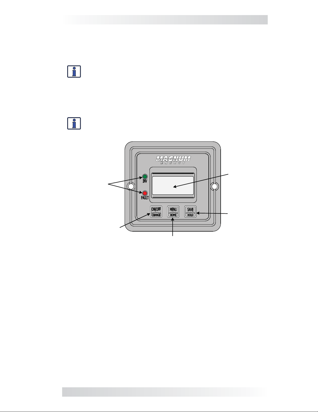
Figure 1-1, Front Panel Features.......................................................... 1
Figure 2-1, Cut-Out Dimensions for Flush Mounted Remote ..................... 3
Figure 2-2, Bezel Dimensions for Surface Mounted Remote ..................... 3
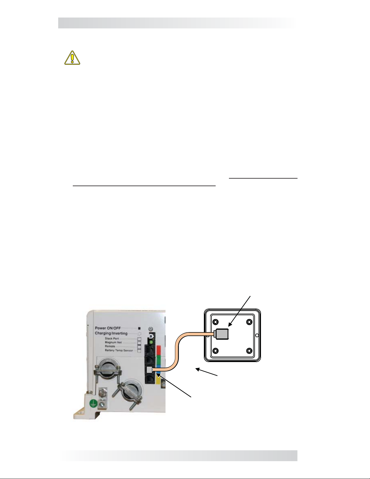
Figure 2-3, Remote Control Connections ............................................... 4
Figure 3-1, Scrolling Home Screens ..................................................... 5
Figure 3-2, AC IN Selections ............................................................... 6
Figure 3-3, Search Watts Selections ..................................................... 7
Figure 3-4, Battery Amp-Hours Selections............................................. 8
Figure 3-5, Battery Type Selections.................................................... 10
Figure 3-6, Charge Rate Selections .................................................... 11
Figure 3-7, LBCO: Low Battery Cut-Out Selections ............................... 12
Figure 3-8, VAC Dropout Selections.................................................... 13
Figure 3-9, Power Saver Selections .................................................... 14
Figure 3-10, Equalize Selections ........................................................ 14
Figure 3-11, Charger Standby Selections ............................................ 15
Figure 3-12, Power On Selections ...................................................... 16
Figure 3-13, TECH Menus ................................................................. 17
Figure 4-1, ME-MR Remote Menu Map ................................................ 18
Figure 5-1, ME-MR Front Panel Controls and Indicators ......................... 19
Figure 5-2, Inverter Standby Mode .................................................... 21
Figure 5-3, Inverting Mode ............................................................... 21
Figure 5-4, Off Mode........................................................................ 22
Figure 5-5, Searching Mode .............................................................. 22
Figure 5-6, Absorb Charging Mode ..................................................... 22
Figure 5-7, Bulk Charging Mode......................................................... 23
Figure 5-8, Charger Standby Mode..................................................... 23
Figure 5-9, Charging Mode................................................................ 23
Figure 5-10, Equalizing Mode ............................................................ 24
Figure 5-11, Float Charging Mode ...................................................... 25
Figure 5-12, Full Charge Mode........................................................... 25
Figure 5-13, Load Support AAC Mode ................................................. 25
Figure 5-14, Load Support VDC Mode................................................. 26
Figure 5-15, Unknown Mode ............................................................. 26
Figure 5-16, AC Overload Fault.......................................................... 27
Figure 5-17, BackFeed Fault.............................................................. 27
Figure 5-18, Breaker Tripped Fault ..................................................... 28
Figure 5-19, Dead Battery Charge Fault.............................................. 28
Figure 5-20, FET Overload Fault......................................................... 28
Figure 5-21, High Battery Fault ......................................................... 29
Figure 5-22, High Battery Temp Fault ................................................. 29
Figure 5-23, High Volts AC Fault ........................................................ 30
Figure 5-24, Low Battery Fault .......................................................... 30

v ©2013 Magnum Energy, Inc.
List of Tables
Table 3-1, Battery Amp-Hrs to Absorb Charging Time ............................. 8
Table 3-2, Battery Size to Battery Amp-Hours (estimated) ...................... 9
Table 3-3, Battery Type to Charge Voltages ......................................... 10
Table 3-4, ME-MR’s Inverter/Charger Default Settings........................... 17
Table 5-1, LED Indicator Guide .......................................................... 35
Table 6-1, Remote Troubleshooting .................................................... 36
List of Figures (Cont.)
Figure 5-25, No Communication ........................................................ 30
Figure 5-26, Overcurrent Fault .......................................................... 31
Figure 5-27, Overtemp Fault ............................................................. 31
Figure 5-28, Stuck Relay Fault........................................................... 32
Figure 5-29, Tfmr Overtemp Fault...................................................... 32
Figure 5-30, Unknown Fault .............................................................. 32
Figure 5-31, Stack Clock Fault........................................................... 33
Figure 5-32, Stack Mode Fault........................................................... 33
Figure 5-33, Stack Phase Fault .......................................................... 33
Figure 5-34, Internal Bridge Fault ...................................................... 34
Figure 5-35, Internal Charger Fault .................................................... 34
Figure 5-36, Internal NTC Sensor Fault ............................................... 34
Figure 5-37, Internal Relay Fault ....................................................... 35
Figure 6-1, Performing an Inverter Reset ............................................ 38

©2013 Magnum Energy, Inc. 1
1.0 Introduction
1.0 Introduction
The ME-MR remote control allows you to monitor and customize the basic
operating parameters of your Magnum inverter/charger. This remote can be
used on all Magnum inverter/charger models.
Info: The ME-MR remote control has minimal settings available
from its menu. Careful consideration should be given to choosing
this remote over the full featured ME-RC when customizing the
inverter/charger for your particular system.
The ME-MR25 comes standard with a 25-foot, 4-conductor telephone cable
and includes non-volatile memory (preserves adjustable settings, even if
power to the remote or inverter is removed).
Info: This manual is for the ME-MR remote with revision 1.1 or
higher. See Section 3.2.12 (TECH Menu) on page 16 for information
on how to determine your revision level.
LCD
Display
LED
Indicators
SAVE/
HOLD
Button
ON/OFF
/CHANGE Button MENU/HOME
Button
The ME-MR is equipped with the following features:
• LED Indicators –The at-a-glance LEDs provide a quick indication of
the inverter’s status, or notifies you if a fault is present.
• LCD Display –The LCD display is a 8 x 2 line (16 characters total),
alphanumeric display used for setting up the inverter/charger operation, as
well as viewing current status or fault messages.
• ON/OFF or CHANGE Button –This button enables you to turn the
inverter on and off, and also serves as a “change” button to navigate through
the available settings for each menu.
• MENU or HOME Button –This button accesses the remote’s menus.
You can also return directly to the scrolling Home screens by pressing and
holding this button for 2 seconds. See also Figure 3-1.
• SAVE or HOLD Button –This button serves as a “save” button to
retain your settings. This button also is used as a “hold” button to stop the
Home screens from scrolling (press and hold the button for 2 seconds).
Figure 1-1, Front Panel Features

2 ©2013 Magnum Energy, Inc.
2.0 Installation
2.0 Installation
Review the Important Safety Instructions on page ii before proceeding with
the installation of your remote.
WARNING: Installations should be performed by qualified per-
sonnel, such as a licensed or certified electrician. The installer
determines which safety codes apply, and ensures all applicable
installation requirements are followed. Applicable installation codes
vary depending on the specific location and application.
2.1 Pre-Installation
Before proceeding, read the entire Installation section to determine how best
to install your ME-MR remote. The more thorough you plan in the beginning,
the better your inverter needs will be met.
2.1.1 Installation Guidelines
• Before connecting any wires, determine the remote cable’s route through-
out the home or vehicle/boat both to and from the inverter.
• Always check for existing electrical, plumbing, or other areas of potential
damage before drilling or cutting into walls to mount the remote.
• Make sure all wires have a smooth bend radius and do not become kinked.
• If installing this remote in a boat, RV or truck, ensure the conductors
passing through walls, bulkheads, or other structural members are
protected to minimize insulation damage such as chafing, which can be
caused by vibration or constant rubbing.
2.1.2 Unpacking and Inspection
Carefully remove the ME-MR remote from its shipping container and inspect
all contents. Verify the following items are included:
• The ME-MR remote
• 25’ remote cable
• Two #6 x ½” Phillips screws
• ME-MR Owner’s Manual
If items appear to be missing or damaged, contact your authorized Magnum
dealer or Magnum Energy, Inc. Save your proof-of-purchase as a record of
your ownership; it is needed if the unit should require in-warranty service.
2.1.3 Tools Required
Installing the remote control is simple and requires the following tools:
• Phillips screwdriver • Level • Drill
• Cut-out tool (knife/saw) • Pencil • Drill bit (7/64”)
2.2 Installation Procedure
Select an appropriate location to install the ME-MR remote control. Allow
ample room to access the remote’s buttons and to view the LEDs. Ensure
the viewing angle of the display is appropriate. You can either flush mount
(concealing the connection) or surface mount the remote.

©2013 Magnum Energy, Inc. 3
2.0 Installation
Figure 2-1, Cut-Out Dimensions for Flush Mounted Remote
Figure 2-2, Bezel Dimensions for Surface Mounted Remote
2 ⅜"
1 ⅛"
1 ⅛"
2 11/16"
(6.03 cm)
(2.86 cm)
2 ⅜"
(6.03 cm)
(2.86 cm)
(6.83 cm)
Side view Back view
1⅛"
2 ⅛" (5.4 cm)
Bezel side view
Bezel front view
(2.86 cm)
3 ⅛" (7.94 cm)
2 ⅛" (5.4 cm)
3 ⅛" (7.94 cm)
2.2.1 Flush Mounting the Remote
After selecting the desired location for flush mounting the remote, cut out
a square mounting hole measuring 2⅜” x 2⅜” (see Figure 2-1). Place the
remote into the cutout, and then use the remote to mark and pre-drill two
⅛” holes for the two supplied #6 x ½” Phillips flat head mounting screws.
2.2.2 Surface Mounting the Remote using the Bezel
After selecting the desired location for surface mounting the remote, use the
bezel (not supplied) as a template to mark the mounting holes. Mark and
pre-drill four ⅛” holes (see Figure 2-2). Mount the bezel using the four #6
x ¾” screws.

4 ©2013 Magnum Energy, Inc.
2.0 Installation
Figure 2-3, Remote Control Connections
BACK
RJ11 Connection
Magnum Inverter
Remote Cable
Remote Port (blue)
2.2.3 Connecting the Remote
CAUTION: When connecting battery power to the inverter, all battery
negative connections must be connected prior to the battery posi-
tive connections. When removing battery power from the inverter,
the battery positive should be removed before any battery negative
connections are disconnected. This prevents any communication
chips/lines from becoming the DC return path to the battery—causing
permanent damage to all connected accessories.
Summation: Ensure all battery negative circuits are always con-
nected before connecting or disconnecting battery positive.
1. Route the remote cable between the remote and the inverter/charger. This
25’ cable is a 4-wire telephony standard with RJ11 connectors on each
end. A standard telephone cable (with 4 conductors) may be substituted
if the provided remote cable cannot be used.
2. Connect the remote cable to the inverter/charger’s Remote port (blue
label). Refer to Figure 2-3.
3. Connect the inverter to the batteries, but ensure the inverter is off and
that no AC power is connected to the inverter.
4. While monitoring the front of the remote, connect the other end of the re-
mote cable into the RJ11 jack on the back side of the remote (Figure 2-3).
5. Immediately upon connecting the remote cable the LEDs will illuminate
as the unit goes through a self-test. After the initial self-test, text should
appear with a system status message indicating the current state of
the inverter/charger. If not, please refer to the Troubleshooting section.
6. Next, mount the remote to the desired surface or to the bezel (using
the two supplied #6 x ½” Phillips flat head screws). The remote is ready
for setup.

©2013 Magnum Energy, Inc. 5
3.0 Setup
3.0 Setup
When the ME-MR remote is connected to a Magnum inverter/charger, the
remote’s settings determine the inverter/charger’s operating parameters.
The default settings in the remote (see Table 3-4) are adequate for most
installations. However, you can change some of the operating parameters if
needed. This section shows you how to navigate the remote, and gives you
an understanding of the function of each adjustable setting.
3.1 Navigating the Remote
The ME-MR has menu items and adjustable settings that provide the ability to
configure your inverter/charger to your specific parameters.
Info: See Figure 4-1 for a complete map of the remote’s menu
items and adjustable settings.
The items on the remote’s front panel are used to find, adjust, and save the
desired setting. They are:
• LCD Display –The LCD display shows menu items, adjustable settings,
and the meter’s display information.
Info: The LCD display returns to the scrolling Home screens to show
inverter status, DC voltage and current, and any fault present (if ap-
plicable) after 30 seconds—if no buttons have been pressed.
Info: When the ”←” (left facing arrow) symbol is shown on the
display, it indicates that the displayed setting has been selected
and will be used.
• ON/OFF/CHANGE Button –Allows you to quickly scroll through and
select various menu items and settings after pressing the MENU button.
• MENU/HOME Button –Allows easy access to the menu items that can
help with configuring, monitoring, and troubleshooting your inverter/
charger. Press and hold this button (2 seconds) to return to the scrolling
Home screens (Figure 3-1).
• SAVE/HOLD Button –Saves the menu item displayed on the screen. A
saved setting is denoted by the arrow symbol. Press and hold this button
(2 seconds) to stop the Home screens from scrolling (“HOLD” displays).
Press once to view the next Home screen. Press and hold again (2 sec-
onds) to resume scrolling of the Home screens (“SCROLL” displays).
STATUS
Invert
FAULT !
Low Batt
BATTERY
11.4V
BATTERY
- 0A
Note: Fault screen only appears if a fault has been detected
Battery Voltage
Battery Current
Inverter/Charger
Status
Inverter/Charger
Fault
Figure 3-1, Scrolling Home Screens

6 ©2013 Magnum Energy, Inc.
3.0 Setup
3.2 Remote Menu Items
This section covers the function of each menu item and explains what con-
figurable settings are available from each menu.
3.2.1 AC IN Menu
Use this menu as a quick means of changing your AC IN setting to coordinate
with the circuit breaker rating from the incoming AC source.
• AC IN – This selection ensures the inverter’s AC loads receive the maxi-
mum current available from the utility or your generator power. Whenever
the utility or generator is connected to the inverter, the current used to
power the AC loads and to charge the batteries is monitored. When the
total current used to power the AC loads and charge the batteries begins
to approach the AC IN setting, the current that was used for charging
the batteries will automatically be reduced. This ensures the AC loads
have all the available current when needed. The feature is not available
on MM and MMS Series inverter/chargers.
Default setting: AC IN = 30 Amps
Range: 5 Amps, 15 Amps, 30 Amps, 50 Amps
Where to set: Adjust the AC IN setting to match the current rating of the
utility power or the generator’s circuit breaker. If using multiple AC sources
(utility and generator) through an AC transfer switch, adjust this setting to
the smaller AC breaker size. This setting is dependent on the stability of the
AC source. If using a generator, factors such as altitude and output voltage
regulation may require a lower setting than the generator’s breaker size. If
the breaker on the AC source is tripping (because it is a weak breaker), try
reducing this setting to the next lower level.
Note: If the ME-MR is connected to a MSH-RE inverter, the AC IN setting
applies to both inputs (AC1 and AC2).
CAUTION: The AC IN setting does not limit the current to the
inverter loads. If the current to the loads on the output of the in-
verter are greater than the circuit breaker rating on the incoming
AC source, you may experience nuisance tripping of this breaker.
Bottom line shows
current “saved” setting
If this setting is correct,
press MENU button to
access different menu items
If a different setting
is required:
press press press
To save the current
setting displayed:
ON/OFF
CHANGE
MENU
HOME
SAVE
HOLD
AC IN
30 Amps
AC IN
30 Amps
AC IN
5 Amps
AC IN
15 Amps
AC IN
50 Amps
Figure 3-2, AC IN Selections

©2013 Magnum Energy, Inc. 7
3.0 Setup
Figure 3-3, Search Watts Selections
Bottom line shows
current “saved” setting
If this setting is correct,
press MENU button to
access different menu items
If a different
setting is required:
press press press
To save the current
setting displayed:
ON/OFF
CHANGE
MENU
HOME
SAVE
HOLD
SEARCH
Off
SEARCH
20 Watt
SEARCH
5 Watt
SEARCH
5 Watt
3.2.2 Search Watts Menu
• SEARCH – This selection allows you to turn off the Search Watts feature,
or to adjust the power level to determine when the feature becomes
active. If this feature is not needed, select SEARCH = Off. When the
Search Watts feature is turned off, the inverter continuously provides
full AC voltage to the loads.
Default setting: SEARCH = 5 Watts
Range: Off, 5 Watts, 20 Watts
Info: When the Search Watts feature is active “Search” appears
on the bottom line of the LCD display, and the green INV LED will
slowly flash.
What is the Search Watts feature? This feature is used to help save bat-
tery power by reducing the inverter’s output to search pulses when there
is no detectable load. If someone turns on a load greater than the wattage
level setting while the inverter is searching, the inverter will start inverting
to provide full voltage on its output.
Should I use the Search Watts feature? If the inverter can spend a great
deal of time searching (to reduce the power drain on your batteries) and you
can tolerate small loads (less than 5 watts) from being on, then the Search
Watts feature should be used. However, if you require some small loads (e.g.,
digital clocks, satellite receivers, answering machines, etc.,) to always be on,
then this feature should be turned off (SEARCH = Off).
Where to set: The SEARCH Watts setting should be adjusted to the same
power level (or the next lower setting) of the smallest load that you want to
run. If you don’t know the wattage of the smallest load you want to run, turn
the switch for the load on and then decrease the SEARCH Watts setting until
the load comes on and stays on.
Example: You have reviewed all the loads you want to run and deter-
mined that the smallest load is a 20 watt light. Set SEARCH = 20 Watt.
Whenever you turn on any load (because all the loads are greater than
20 watts), the inverter will stop searching and start inverting to deliver
power to the load.
Info: Even though the Search Watts feature is on, some connected
equipment may draw enough current even while off to keep the
inverter in Invert mode.

8 ©2013 Magnum Energy, Inc.
3.0 Setup
3.2.3 Battery Amp-Hours Menu
• BAT AHRS – This selection is used to select the approximate capacity
of the battery bank that is connected to the inverter (in battery amp-
hours). This setting determines the time the battery charger is in the
Absorb Charging stage (i.e., absorption time). See Table 3-1 to correlate
the battery capacity to the absorption time.
Default setting: BAT AHRS = 400 AH
Range: 200 AH, 400 AH, 800 AH
Table 3-1, Battery Amp-Hrs to Absorb Charging Time
Battery Amp-Hours Selected Absorb Charging Time
Batt AmpHrs = 200 60 minutes
Batt AmpHrs = 400 90 minutes
Batt AmpHrs = 800 120 minutes
Where to set: Select the setting based on the 20-hour Amp-Hour (AH)
capacity of your battery bank.
How do I determine my battery AH capacity? The inverter requires deep
cycle batteries, which are specifically made for continuous use. Deep cycle
batteries are rated either by: a) amp-hours, or b) reserve capacity in minutes.
• Amp-hour (AH) capacity is a measurement of how many amps a battery
can deliver for a specified length of time (usually 20 hrs) until the
voltage achieves 1.75 VDC/cell at 80° F.
• Reserve Capacity (RC) is a measure of how many minutes a battery can
deliver a certain amount of current (usually 25A) while maintaining a
voltage above 1.75 VDC/cell at 80° F.
Info: If using the Reserve Capacity (25A), the 20 hour AH capacity
can be estimated by multiplying ‘reserve capacity’ by 50%.
Bottom line shows
current “saved” setting
If this setting is correct,
press MENU button to
access different menu items
If a different setting
is required:
press press press
To save the current
setting displayed:
ON/OFF
CHANGE
MENU
HOME
SAVE
HOLD
BAT AHRS
400 AH
BAT AHRS
200 AH
BAT AHRS
400 AH
BAT AHRS
800 AH
Figure 3-4, Battery Amp-Hours Selections
Table 3-2 on the facing page provides an estimated 20 hour AH capacity
based on the group/code size, physical size, and the voltage of the battery.
If you are not sure of your battery’s 20 hour AH rating, consult your battery
manufacturer/dealer or use Table 3-2 to obtain an estimate.

©2013 Magnum Energy, Inc. 9
3.0 Setup
Table 3-2, Battery Size to Battery Amp-Hours (estimated)
Group/
Code Size Physical Size
(L” x W” X H”) Battery
Voltage Battery AHrs
(20 hour rate)
GC-2 (Golf Cart) 10 3/8 x 7 13/16 x 10 5/8 6V 220 AHrs
L16 11 11/16 x 7 x 16 11/16 6V 375 AHrs
Group 22 9 1/2 x 6 7/8 x 8 5/16 12V 55 AHrs
Group 24 10 1/4 x 6 13/16 x 8 7/8 12V 70 AHrs
Group 27 12 1/16 x 6 13/16 x 8 7/8 12V 95 AHrs
Group 31 13 x 6 13/16 x 9 7/16 12V 110 AHrs
4D 20 3/4 x 8 3/4 x 9 7/8 12V 200 AHrs
8D 20 3/4 x 11 1/8 x 9 7/8 12V 225 AHrs
Once you’ve determined the AH capacity of each battery, review how your
batteries are connected (parallel or series) to determine the total amp-hour
capacity of the battery bank.
Parallel connection
When batteries are connected in parallel (positive to positive, negative to
negative) they increase the amp-hour capacity of the battery bank, but the
voltage remains the same.
Example: You have a 12-volt battery bank with three 12-volt batteries
that are rated at 125 amp-hours (AH) each. Each of the positive terminals
are connected together and each of the negative terminals are connected
together, which means they are connected in parallel. The amp-hours of
each battery connected in parallel are added together (125 AH + 125 AH
+ 125 AH = 375 AH), but the voltage of the battery bank stays the same
(12 VDC).
Series connection
When batteries are connected in series (positive to negative) they increase
the voltage of the battery bank, but the amp-hour rate remains the same.
Example: You have a 12-volt battery bank with two 6-volt batteries
that are rated at 220 amp-hours (AH) each. The positive terminal of
the first battery is connected to the negative terminal of the second
battery, which means these batteries are connected in series. Since the
two 6-volt batteries are connected in series, the voltage of the batteries
are added together to produce 12-volts (6 VDC + 6 VDC = 12 VDC), but
the amp-hour capacity of the battery bank does not change (220 AH).
In battery banks where you have batteries connected in series and in parallel
—the rules are the same. The batteries connected in series are referred to
as a “series string” and the amp-hour capacity doesn’t change. Each series
string is connected together in parallel to increase the amp-hour capacity.
Add the amp-hour capacity of each series string connected in parallel to
determine the total amp-hour capacity of the battery bank.

10 ©2013 Magnum Energy, Inc.
3.0 Setup
3.2.4 Battery Type Menu
• BAT TYPE – This menu is used to select the battery type, which
determines the battery charge profile and ensures the batteries are
receiving the proper charge voltage. The fixed voltage options are: GEL
(for Gel batteries), Flooded (for liquid lead acid batteries), AGM 1 (for
Lifeline AGM batteries), and AGM 2 (for East Penn/Deka/Discover/Trojan
AGM batteries). Refer to Table 3-3 to determine the specific charge
voltage based on the battery type selected.
Default setting: BAT TYPE = Flooded
Info: The voltage settings shown in Table 3-3 are based on the
Battery Temperature Sensor (BTS) being disconnected, or at a
temperature of 77° F (25° C). If the BTS is connected, the actual
charge voltage increases if the temperature around the BTS is colder
than 77° F (25° C), and decreases if hotter than 77° F (25° C). This
ensures the batteries receive the correct charge voltage even if they
become cold or hot.
Table 3-3, Battery Type to Charge Voltages
Battery
Type Inverter
Voltage Absorption
Voltage Float
Voltage Equalization
Voltage
GEL
12 VDC 14.1 VDC 13.6 VDC 14.1 VDC1
24 VDC 28.2 VDC 27.2 VDC 28.2 VDC1
48 VDC 56.4 VDC 54.4 VDC 56.4 VDC1
Flooded
12 VDC 14.6 VDC 13.4 VDC 15.5 VDC
24 VDC 29.2 VDC 26.8 VDC 31.0 VDC
48 VDC 58.4 VDC 53.6 VDC 62.0 VDC
AGM 12
12 VDC 14.3 VDC 13.1 VDC 15.5 VDC
24 VDC 28.6 VDC 26.2 VDC 31.0 VDC
48 VDC 57.2 VDC 52.4 VDC 62.0 VDC
AGM 23
12 VDC 14.5 VDC 13.5 VDC 14.5 VDC1
24 VDC 29.0 VDC 27.0 VDC 29.0 VDC1
48 VDC 58.0 VDC 54.0 VDC 58.0 VDC1
Note 1: Voltage same as absorption voltage – to prevent equalization.
Note 2: Specifications for Concord (Lifeline Series) AGM batteries.
Note 3: Specifications for East Penn, Deka, Discover and Trojan AGM batteries.
Figure 3-5, Battery Type Selections
Bottom line shows
current “saved” setting
If this setting is correct,
press MENU button to
access different menu items
If a different setting
is required:
press press press
To save the current
setting displayed:
ON/OFF
CHANGE
MENU
HOME
SAVE
HOLD
BAT TYPE
GEL
BAT TYPE
Flooded
BAT TYPE
AGM 1
BAT TYPE
Flooded
BAT TYPE
AGM 2

©2013 Magnum Energy, Inc. 11
3.0 Setup
3.2.5 Charge Rate Menu
• CHG RATE –This selection is used to set the maximum charge rate
allowed to charge the batteries during Bulk, Absorption, Float, and
Equalize charging. The CHG RATE = 10% setting is available to help
minimize charging, while continuing to allow pass-through power.
Default setting: CHG RATE = 100%
Range: 10%, 50%, 100%
The charge rate selections are provided as a percentage of the inverter/
charger’s maximum charging capability. Refer to the label on the side of
the inverter or to the inverter/charger owner’s manual to determine its
maximum charge rate. Once you find this maximum charge rate, determine
the percentage needed to limit the charge rate to your battery bank.
Example: If the maximum charge rate of your inverter/charger is 100
amps and you need to limit the charge rate to 50 amps, choose the CHG
RATE = 50% selection (50 amps = 50% of 100 amps).
Info: The topology of the Magnum inverter when connected to an
AC source overrides the setting, and starts charging if the battery
voltage is <12 VDC (12-volt models), <24 VDC (24-volt models)
or <48 VDC (48-volt models).
Where to set: The maximum charge rate is generally set to a C/5* rate (C =
the total amp-hour capacity of the battery bank—using the 20 hour AH rate).
The C/5 rate is usually used when the objective is to charge the batteries as
quickly as possible (i.e., 400 AH ÷ 5 = 80 amp maximum charge rate). A lower
rate such as C/20* is used when the batteries need to be charged as slow as
possible. The ME-MR provides three settings for charge rate adjustment—10,
50, and 100%. Multiply this percentage and the max charge rate of the
inverter to find the closest setting to the desired charger output.
CAUTION: The C/5 or C/20 charge rate settings are guidelines;
they are not requirements on how you should set your battery
charge rate. For specific charge rate requirements, refer to your
battery manufacturer.
Info: If multiple inverter/chargers are used on a single battery
bank, you must ensure that the total charge rate from all inverter/
chargers is limited to the max charge rate needed for your battery
bank. This setting only limits the charging on each inverter/charger
individually, not on all inverter/chargers.
* C/5 or C/20 rate – Charge rates are commonly expressed as a ratio of the total
amp-hour (AH) capacity of the battery bank. For example, with a 400 AH battery
bank (C = 400), the C/5 charge rate is 80 A (400/5 = 80 A).
Bottom line shows
current “saved” setting
If this setting is correct,
press MENU button to
access different menu items
If a different setting
is required:
press press press
To save the current
setting displayed:
ON/OFF
CHANGE
MENU
HOME
SAVE
HOLD
CHG RATE
100%
CHG RATE
10%
CHG RATE
100%
CHG RATE
50%
Figure 3-6, Charge Rate Selections

12 ©2013 Magnum Energy, Inc.
3.0 Setup
3.2.6 Low Battery Cut-Out (LBCO) Menu
• LBCO –This menu is used to set the DC voltage level that turns off
the inverter to help protect the batteries from over-discharge damage.
Selections are from 9 VDC to 11 VDC (12-volt inverter models), 18 VDC
to 22 VDC (24-volt inverter models), or 36 VDC to 44 VDC (48-volt
inverter models). If the battery voltage drops below the LBCO selected
setpoint continuously for more than one minute, the FAULT LED will
come on, the inverter will turn off, and the display shows “FAULT! Low
Bat” (low battery status). If the battery voltage falls below 8.5 volts (12-
volt models), 17.0 volts (24-volt models) or 34.0 (48-volt models), the
FAULT LED and Low Bat status will be immediate.
Default settings: LBCO = 10 VDC (12-volt models), 20 VDC (24-volt
models) or 40 VDC (48-volt models).
Range: 9 VDC, 10 VDC, 11 VDC (12-volt models, x2 for 24v, x4 for 48v)
Info: The inverter will automatically begin to start inverting when
the DC voltage increases to ≥12.5 VDC (12-volt models), ≥25.0
VDC (24-volt models) or ≥50.0 VDC (48-volt models). If AC power
is available and connected to the inverter’s input the inverter will
automatically clear the Low Battery fault, pass the input AC power
to the output, and begin charging the batteries.
Where to set: To cycle the batteries slightly but not discharge them more
than 20%*, the LBCO setting should be set to 11 VDC (12-volt models), 22
VDC (24-volt models) or to 44 VDC (48-volt models). In some applications,
such as installations in an off-grid home or when doing a lot of dry-camping
in your RV, you may want to cycle down to 25%* by setting the LBCO to
10 VDC (12-volt models), 20 VDC (24-volt models) or to 40 VDC (48-volt
models). In extreme circumstances, you have the ability to discharge the
batteries to 80%* by setting the LBCO to 9 VDC (12-volt models), 18 VDC
(24-volt models), or to 36 VDC (48-volt models) before recharging.
* These discharge percentages are rough estimates; for accurate battery monitoring,
a battery monitor such as Magnum’s ME-BMK and the ME-RC remote is required.
Info: The inverter will automatically begin to start inverting when the
DC voltage increases to ≥12.5 VDC (12-volt models), ≥25.0 VDC
(24-volt models) or to ≥50.0 VDC (48-volt models). If AC power
is available and connected to the inverter’s input, the inverter will
automatically clear the Low Battery fault, pass the input AC power
to the output, and begin charging the batteries.
Bottom line shows
current “saved” setting
If this setting is correct,
press MENU button to
access different menu items
If a different setting
is required:
press press press
To save the current
setting displayed:
ON/OFF
CHANGE
MENU
HOME
SAVE
HOLD
LBCO
10 VDC
LBCO
10 VDC
LBCO
9 VDC
LBCO
11 VDC
Note: Values shown are for a 12-volt inverter
Figure 3-7, LBCO: Low Battery Cut-Out Selections

©2013 Magnum Energy, Inc. 13
3.0 Setup
3.2.7 VAC Dropout Menu
• VAC DROP – This selection is used to set the minimum AC voltage that
must be present on the input before the inverter/charger switches from
Invert to Charge mode. For example, if this setting is set to VAC DROP
= 60 VAC, then the AC input voltage must be above 60 volts before the
inverter will switch from Invert mode to Charge mode. This setting also
determines the minimum AC voltage threshold where the inverter/char-
ger transfers from the AC input (utility/shore or generator) and begins
inverting. This protects AC loads from utility outages.
Default setting: VAC DROP = 80 VAC for North American units; 150
VAC for export models.
Range: 60 VAC, 80 VAC, and 100 VAC for 120v units (North America);
and 110 VAC, 150 VAC, and 190 VAC for 230v units (for export)
Where to set: It depends on the application and what you are using as the
AC source. The settings not only look at the incoming voltage to determine
when to transfer, but they also determine the response sensitivity to incoming
voltage fluctuations. Use the 100 VAC dropout setting when the AC source
is well regulated and you are operating devices that are sensitive to voltage
fluctuations. Use the 80 VAC or lower setting (60 VAC) when the AC source
may have significant fluctuations in RMS voltage. These settings are highly
recommended if using a generator for charging.
Note: If the ME-MR is connected to a MSH-RE inverter, the VAC Dropout
setting applies to both inputs (AC1 and AC2).
Figure 3-8, VAC Dropout Selections
Bottom line shows
current “saved” setting
If this setting is correct,
press MENU button to
access different menu items
If a different setting
is required:
press press press
To save the current
setting displayed:
ON/OFF
CHANGE
MENU
HOME
SAVE
HOLD
VAC DROP
80 VAC
VAC DROP
80 VAC
VAC DROP
100 VAC
VAC DROP
80 VAC
3.2.8 Power Save Menu
• PWR SAVE
–
This setting allows you to turn the Power Save feature
on or off.
Default setting:
PWR SAVE = On
Range:
On, Off
What is the Power Saver feature? The Power Saver feature causes the
LCD backlight and LEDs on the remote display to turn off to conserve energy.
The remote goes into Power Saver mode if there has not been a button press
or fault message for 15 minutes. Whenever the remote goes into the Power
Saver mode, the LCD backlight and LEDs can be
reactivated by pressing any
button on the remote.

14 ©2013 Magnum Energy, Inc.
3.0 Setup
If you have a fault during the Power Saver mode, the LCD backlight, and the
FAULT LED will come on and stay on as long as the fault is detected. If you
want the LCD backlight and LEDs to always be on, select PWR SAVE = Off.
Bottom line shows
current “saved” setting
If this setting is correct,
press MENU button to
access different menu items
If a different setting
is required:
press press press
To save the current
setting displayed:
ON/OFF
CHANGE
MENU
HOME
SAVE
HOLD
PWR SAVE
On
PWR SAVE
Off
PWR SAVE
On
3.2.9 Equalize Menu
• EQUALIZE – This menu allows you to equalize the batteries after a Float
Charge is achieved. Equalizing should only be attempted by experienced
users.
Default setting: EQUALIZE = Disabled
Range: Disabled, Request, EQing
What is equalizing? Equalizing is a controlled overcharge of the batteries.
During this process, there will be excessive gassing of the batteries. This
condition is not only corrosive, but can also be dangerous as hydrogen
gasses are emitted during the charging process.
WARNING: Only equalize in well ventilated areas. Consult your
battery’s manufacturer for recommendations on equalizing.
Info: Equalization can only be accomplished when the charger status
is “FLOAT” or “Full Chg”.
Info: Equalization charging is not available if either GEL or AGM 2 is
selected from the Battery Type menu.
Bottom line shows
current “saved” setting
If this setting is correct,
press MENU button to
access different menu items
To start
equalization:
press press
ON/OFF
CHANGE
MENU
HOME
EQUALIZE
Disabled
EQUALIZE
Disabled
EQUALIZE
EQing
EQUALIZE
Request
Figure 3-9, Power Saver Selections
Figure 3-10, Equalize Selections
Other manuals for ME-MR
1
Table of contents
Other Magnum Energy Remote Control manuals

Magnum Energy
Magnum Energy ME-RC User manual

Magnum Energy
Magnum Energy MM-R User manual

Magnum Energy
Magnum Energy ME-MR Series User manual

Magnum Energy
Magnum Energy ME-MR User manual

Magnum Energy
Magnum Energy ME-ARC50 User manual

Magnum Energy
Magnum Energy ME-RC User manual

Magnum Energy
Magnum Energy ME-ARC User manual

Magnum Energy
Magnum Energy MM Series Operating instructions

Magnum Energy
Magnum Energy ME-RC User manual

Magnum Energy
Magnum Energy MM-R User manual