Magnum Energy ME-RC User manual

Owner’s Manual
(for Revision 2.5 or higher)
Inverting
DC: 12.6V 50A
ME-RC
Remote Control

Disclaimer of Liability
Since the use of this manual and the conditions or methods of installation,
operation, use and maintenance of the ME-RC are beyond the control of
Magnum Energy Inc., this company does not assume responsibility and
expressly disclaims liability for loss, damage or expense, whether direct,
indirect, consequential or incidental, arising out of or anyway connected with
such installation, operation, use, or maintenance.
Due to continuous improvements and product updates, the images shown in
this manual may not exactly match the unit purchased.
Restrictions on Use
The ME-RC remote shall not be used in connection with life support systems,
life saving or other medical equipment or devices. Using the ME-RC with this
particular equipment is at your own risk.
Important Product Safety Instructions
This manual contains important safety instructions that must be followed
during the installation and operation of this product. Read all instructions
and safety information contained in this manual before installing or using
this product.
• All electrical work must be performed in accordance with local, state and
federal electrical codes.
• This product is designed for indoor / compartment installation. It must not
be exposed to rain, snow, moisture or liquids of any type.
• Use insulated tools to reduce the chance of electrical shock or accidental
short circuits.
• Remove all jewelry such as rings, watches, bracelets, etc., when installing
or performing maintenance on the inverter.
• Always disconnect the batteries or energy source prior to installing or
performing maintenance on the inverter. Live power may be present at more
than one point since an inverter utilizes both batteries and AC. Turning off
the inverter may not reduce this risk. As long as AC power is connected, it
will pass thru the inverter regardless of the power switch on the inverter or
the ON/OFF INVERTER pushbutton on the remote.
Safety Symbols
To reduce the risk of electrical shock, re, or other safety hazard, the fol-
lowing safety symbols have been placed throughout this manual to indicate
dangerous and important safety instructions.
WARNING: This symbol indicates that failure to take a specied
action could result in physical harm to the user.
CAUTION: This symbol indicates that failure to take a specied ac-
tion could result in damage to the equipment.
Info: This symbol indicates information that emphasizes or supple-
ments important points of the main text.
Remedy: This symbol provides possible solutions for related is-
sues.

©2009 Magnum Energy Inc. i
List of Contents
1.0 Overview .................................................................................... 1
2.0 Installation.................................................................................. 2
2.1 Installation Guidelines ................................................................2
2.2 Tools Required ........................................................................... 2
2.3 Installation Procedure................................................................. 2
3.0 Setup ......................................................................................... 4
3.1 Navigating the Remote’s Menu ..................................................... 4
3.2 Menu Pushbuttons and Menu Items .............................................. 6
3.2.1 SHORE Menu ........................................................................ 6
3.2.2 AGS Menu ............................................................................ 7
3.2.3 METER Menu......................................................................... 7
3.2.4 SETUP Menu ......................................................................... 8
3.2.5 TECH Menu......................................................................... 16
4.0 Menu Map: ME-RC Remote Control ............................................... 18
5.0 Operation.................................................................................. 20
5.1 Front Panel.............................................................................. 20
5.1.1 LED Indicators .................................................................... 20
5.1.2 LCD Display........................................................................ 20
5.1.3 ON/OFF Pushbuttons............................................................ 21
5.1.4 Menu Pushbuttons ............................................................... 21
5.1.5 Rotary SELECT Knob ............................................................ 21
5.2 Operating the Inverter/Charger.................................................. 22
5.2.1 Inverter Mode ..................................................................... 22
5.2.2 Charger mode..................................................................... 22
5.3 System Status Messages........................................................... 23
5.3.1 Inverter Mode Messages....................................................... 23
5.3.2 Charger Mode Messages ....................................................... 24
5.3.3 Fault Mode Messages ........................................................... 27
5.3.4 LED Indicator Guide............................................................. 34
6.0 Troubleshooting ........................................................................ 35
6.1 Troubleshooting Tips - ............................................................. 36
6.1.1 Inverter problems: .............................................................. 36
6.1.2 Charger problems: .............................................................. 36
6.2 Performing an Inverter Reset ..................................................... 37
6.3 Powering-down the Inverter ...................................................... 37
7.0 Limited Warranty ....................................................................... 38
Tables
Table 3-1, Battery AmpHrs to Absorb Charging Time ............................ 10
Table 3-2, Battery Size to Battery Amp-hours (estimated)..................... 11
Table 3-3, Battery Type to Charge Voltages ......................................... 12
Table 3-4, Inverter/Charger Default Settings ....................................... 17
Table 5-1, LED Indicator Guide .......................................................... 34
Table 6-1, Remote Control Troubleshooting Guide ................................ 35

ii ©2009 Magnum Energy Inc.
List of Figures
Figure 1-1, Front Panel Features.......................................................... 1
Figure 2-1, Remote Cut-Out Dimensions............................................... 3
Figure 2-2, Remote Control Connections ............................................... 3
Figure 3-1, Front Panel Set-up Features................................................ 4
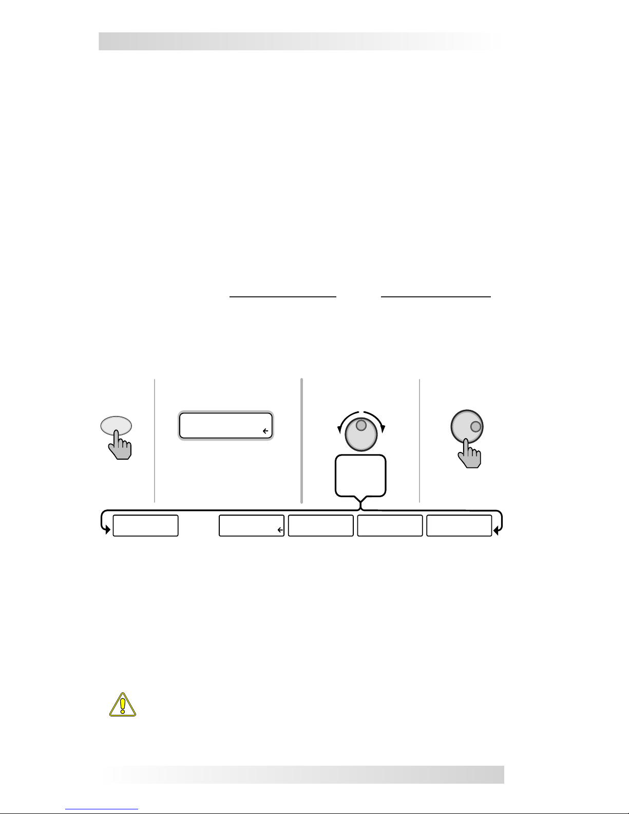
Figure 3-2, SETUP Menu Navigation .................................................... 5
Figure 3-3, SHORE: Shore Max Selections............................................. 6
Figure 3-4, AGS Menu Display ............................................................. 7
Figure 3-5, METER: 01 INV/CHG Meter Display ...................................... 7
Figure 3-6 thru 3-13, SETUP Menu Selections................................... 8-15
Figure 3-14 thru 3-18, TECH Menu Displays/Selection ..................... 16-17
Figure 4-1, Inverter/Charger Menu Map.............................................. 18
Figure 5-1, ME-RC Front Panel Controls and Indicators ......................... 20
Figure 5-2, Off Mode........................................................................ 23
Figure 5-3, Searching Mode .............................................................. 23
Figure 5-4, Inverting Mode ............................................................... 23
Figure 5-5, Charging Mode................................................................ 24
Figure 5-6, Bulk Charging Mode......................................................... 24
Figure 5-7, Absorb Charging Mode ..................................................... 24
Figure 5-8, Float Charging Mode........................................................ 25
Figure 5-9, Full Charge Mode ............................................................ 25
Figure 5-10, Charger Standby Mode................................................... 25
Figure 5-11, Equalizing Mode ............................................................ 26
Figure 5-12, Low Battery Fault .......................................................... 27
Figure 5-13, High Battery Fault ......................................................... 27
Figure 5-14, Overtemp Fault ............................................................. 28
Figure 5-15, AC Overload Fault.......................................................... 28
Figure 5-16, High Volts AC Fault ........................................................ 28
Figure 5-17, Dead Battery Charge Fault .............................................. 29
Figure 5-18, Overcurrent Fault .......................................................... 29
Figure 5-19, FET Overload Fault......................................................... 30
Figure 5-20, Breaker Tripped Fault ..................................................... 30
Figure 5-21, Unknown Fault .............................................................. 30
Figure 5-22, Tfmr Overtemp Fault...................................................... 31
Figure 5-23, Fatal Error $ Fault.......................................................... 31
Figure 5-24, No Inverter Comm......................................................... 31
Figure 5-25, StackClock Fault............................................................ 32
Figure 5-26, Stack Mode Fault........................................................... 32
Figure 5-27, StackPhase Fault ........................................................... 32
Figure 5-28, Internal Bridge Fault ...................................................... 33
Figure 5-29 Internal Charger Fault ..................................................... 33
Figure 5-30, Internal NTC Fault ......................................................... 33
Figure 5-31, Internal Relay Fault ....................................................... 33
Figure 6-1, Performing an Inverter Reset ............................................ 37

©2009 Magnum Energy Inc. 1
1.0 Overview
1.0 Overview
The ME-RC remote control allows you to monitor and customize the operating
parameters to your Magnum inverter/charger. It is the same remote used on
all Magnum inverter/charger models in the ME, MM, MS, and the RD Series
lines so there is no cross-platform confusion.
The ME-RC50 comes standard with a 50 foot, 4-conductor (twisted-pair)
telephone cable and includes non-volatile memory (preserves adjustable
settings, even if power to the remote or inverter is removed). The Magnum
remote control has all of the programming and operation functions included
in an easy-to-use package.
This manual is for the ME-RC with revision 2.5 or higher; see the
TECH: 02 Revisions display on page 16 for information on how to
determine your revision level.
Figure 1-1, Front Panel Features
The ME-RC is equipped with the following features:
• LED Indicators - The at-a-glance LEDs provide the inverter/charger
status in a straightforward way.
• LCD Display - The LCD display is a 16 x 2 line (32 characters total),
alphanumeric display, used for setting up the inverter/charger operation as
well as viewing current status or fault messages.
• ON/OFF Pushbuttons (x2) - Allows the inverter or charger to be
independently and quickly enabled or disabled.
• Menu Pushbuttons (x5) - The menu pushbuttons allow the inverter or
charger to be congured to your specic system preferences. These menus
also allow simple access to menu items that can help with monitoring and
troubleshooting your inverter/charger system.
• Rotary Knob / SELECT button - The rotary encoder knob is similar to
a dash radio knob and used to quickly scroll through and select various menu
items and settings. Pushing this rotary knob allows you to “SELECT” a menu
item or to “save” a setting once it is displayed on the LCD screen.
Inverting
DC: 12.6V 50A

2 ©2009 Magnum Energy Inc.
2.0 Installation
2.0 Installation
Before installing the remote, read the entire installation section to determine
how you are going to install your ME-RC. The more thorough you plan in the
beginning, the better your inverter needs will be met.
Info: Installations should be performed by qualied personnel, such
as a licensed or certied electrician. It is the installer’s responsibility
to determine which safety codes apply and to ensure that all appli-
cable installation requirements are followed. Applicable installation
codes vary depending on the specic location and application.
Info: Review the “Important Product Safety Information” on the
front inside cover page before any installation.
2.1 Installation Guidelines
• Before connecting any wires, determine the remote cable route throughout
the home or vehicle/boat both to and from the inverter.
• Always check for existing electrical, plumbing or other areas of potential
damage BEFORE drilling or cutting into walls to mount the remote.
• Make sure all wires have a smooth bend radius and do not become
kinked.
• If installing this remote in an boat, RV or truck; ensure the conductors
passing through walls, bulkheads or other structural members are protected
to minimize insulation damage such as chang, which can be caused by vi-
bration or constant rubbing.
2.2 Tools Required
Installing the remote control is a simple process and requires the following
tools:
• Phillips screwdriver • Level • Drill
• Cut-out tool (knife/saw) • Pencil • Drill Bit (7/64”)
2.3 Installation Procedure
1. Select an appropriate location to install the remote control. Allow ample
room to access the remote’s adjustment dial and to view the LEDs. Ensure
the viewing angle of the display is appropriate.
2. Refer to gure 2-1 for hole and cutout dimensions.
3. Run the remote cable between the remote and the inverter/charger. This
cable is a 4-wire, twisted-pair, telephony standard with RJ11 connectors on
each end. A standard telephone cable may be substituted if the provided
remote cable is not able to be used.
4. Connect the remote cable into the RJ11 “Remote” port (has blue label) on
the inverter/charger (see gure 2-2).
5. Have the inverter connected to batteries, but ensure the inverter is off and
that no AC power is connected to the inverter.

©2009 Magnum Energy Inc. 3
2.0 Installation
REM O TE Port
(blue label )
RJ11 connection
M agnum Inverter
Rem ote cable
ME-RC
RemoteControl
(backview)
Info: All power to operate the remote control is provided by the
inverter/charger through the remote cable.
6. While monitoring the front of the remote, connect the other end of the cable
into the RJ11 jack on the back-side of the remote (see gure 2-2).
7. Immediately upon connecting the remote cable, all the LED’s will come on
as the unit goes through a self-test. After the initial self-test completes, text
should appear with a system status message indicating the current state of
the inverter/charger. If not, please refer to the troubleshooting section.
8. Secure the remote to the wall using the four 6 x 3/4” screws provided.
9. The remote is ready for set-up.
CUT O UT T H IS
A R E A
5 1/4 "
3 1/4"
2 7/8 "
4 7/8 "
(diagra m no t to sca le )
Figure 2-2, Remote Control Connections
Figure 2-1, Remote Cut-Out Dimensions

4 ©2009 Magnum Energy Inc.
3.0 Setup
3.0 Setup
When the remote is connected to a Magnum inverter/charger, the settings in
the remote control determine the inverter/charger operating parameters. The
default settings in the remote control (see Table 3-4, Inverter/Charger Default
Settings) are adequate for most installations, however you have the option to
change some of the operating parameters if required. This section will show
you how to navigate the remote, give you an understanding of the function of
each adjustable setting and help you decide what setting should be used.
3.1 Navigating the Remote’s Menu
The ME-RC has an internal structure that provides menu items and adjustable
settings that provide the ability to congure your inverter/charger to your
specic parameters.
Info: See gure 4-1, Inverter/Charger Menu Map for a complete map
of the inverter/charger menu items and adjustable settings.
Familiarize yourself with the items on the front panel which are used to nd,
adjust and save the desired setting. They are:
• LCD Display - The bottom line of the LCD display shows the menu items,
adjustable settings or the meters display information.
Info: The bottom line of the LCD display returns to the Home Screen
to show DC voltage and current (see Figure 3-1) after 2 minutes - if
no buttons have been pressed.
Info: When the ”←” (left facing arrow) symbol is shown on the dis-
play, it indicates that the displayed setting has been selected and
will be used.
• Menu Pushbuttons (x5) - These ve menus allow simple access to the
menu items that can help with conguring, monitoring and troubleshooting
your inverter/charger system.
• Rotary SELECT Knob - This knob allows you to quickly scroll through and
select various menu items and settings after pressing a menu pushbutton. This
knob is also used to “save” a setting once it is displayed on the LCD screen
and will refresh the LCD display by holding this knob down for 10 seconds.
Inverting
DC: 12.6V 50A
Rotary
SELECT Knob
LCD
Display
Menu
Buttons
Figure 3-1, Front Panel Set-up Features

©2009 Magnum Energy Inc. 5
3.0 Setup
Figure 3-2, SETUP Menu Navigation
Inverting
BatType=Flooded
4. Turn the SELECT knob to the
desired setting.
Bottom line shows current
setting* (indicated by a ).
Inverting
BatType= AGM 1
When the bottom line shows the
desired setting -
5. Press the SELECT knob to
“save” this desired setting.
Inverting
04 Battery Type
3. Press the SELECT knob .
When the bottom line shows the
desired menu item -
Inverting
01 Search Watts
1. Press the SETUP Menu button .
Bottom line shows a menu item.
2. Turn the SELECT knob to the
desired menu item.
*[if this setting is correct, press
the SELECT knob to continue to
the next menu item].

6 ©2009 Magnum Energy Inc.
3.0 Setup
3.2 Menu Pushbuttons and Menu Items
The ve menu pushbuttons (SHORE, AGS, METER, SETUP or TECH) allow
the inverter/charger system to be congured to your specic preferences.
These menus also allow you to access menu items that can help with moni-
toring and troubleshooting your system.
Read this section to help understand the function of each Menu pushbutton
and the congurable settings - to determine if they should be changed to
optimize the operation of the inverter/charger.
3.2.1 SHORE Menu
This menu pushbutton gives a quick means of changing your Shore Max setting
to coordinate with the circuit breaker rating from the incoming AC source.
SHORE: Shore Max - This selection ensures the inverter AC loads
receive the maximum current available from the utility or generator power.
Whenever the utility or generator is connected to the inverter (thru AC HOT
1), the current used to power the AC loads and to charge the batteries is
monitored. When the total current used to power the AC loads and charge
the batteries begins to approach the Shore Max setting, the current that was
used for charging the batteries will automatically be reduced. This ensures
the AC loads have all the available current when needed.
Default setting: Shore Max = 30A
Where to set: Set the Shore Max setting to match the current rating of
the utility power or generator’s circuit breaker. If using multiple AC sources
(utility and generator) through an AC transfer switch, adjust this setting to
the smaller AC breaker size. This setting is very dependent on the stability
of the AC source. If using a generator, factors such as altitude and output
voltage regulation may require a lower setting than the generator’s breaker
size. For best performance, lower this setting to 1/3 its rated capacity and
gradually increase while ensuring the voltage level stays above the SETUP:
06 VAC Dropout setting.
CAUTION: The Shore Max setting does not limit the current to the
inverter loads. If the current from the loads on the output of the
inverter are greater than the circuit breaker rating on the incoming
AC source, you may experience nuisance tripping on this breaker.
•
press to save
press
SH O R E
rotate to
desired
selection :
Status ...
Shore Max = 5A
Bottom line show s
current “saved” setting
If this setting is correct , press
another m enu button to
access different m enu item s
If a different setting is
required:
Status…
Shore Max = **A
Status...
Shore Max = 60A
Status...
Shore Max = 30A Status...
Shore Max = 40A Status...
Shore Max = 50A
.......
Figure 3-3, SHORE: Shore Max Selections

©2009 Magnum Energy Inc. 7
3.0 Setup
3.2.2 AGS Menu
The AGS menu pushbutton allows the optional Auto Generator Start (AGS)
controller (if installed and networked) to be congured to your specic system
preferences and check status of the AGS.
Info: Refer to the ME-AGS-N Owner’s Manual (part number: 64-
0005) for detailed information on the Magnum Energy Auto Generator
Start (ME-AGS-N) and this menu.
Figure 3-4, AGS Menu Display
3.2.3 METER Menu
Pressing the METER menu pushbutton gives you access to different meters,
which helps determine the status of the inverter/charger and battery sys-
tem.
METER: 01 INV/CHG Meter - This menu provides the DC voltage and
current while either inverting or charging.
The DC: V (Volts) display provides the voltage from the batteries connected to
the inverter. The DC: V accuracy is ±1.5% with a 0.1 VDC resolution.
While inverting, the DC: A (Amps) displays a negative number to show the
battery current used by the inverter. If you are charging, the DC A (amps)
displays a positive number to show the amount of current delivered to the
batteries. The accuracy of this display below 1 amp AC (~10 amps DC @
12VDC) is not detected. When the current into or out of the batteries is
greater than 1 amp AC, the display accuracy is ±20%.
Figure 3-5, METER: 01 INV/CHG Meter Display
METER: 02 BM: SOC thru 06 BM: TECH - These menus allow the
optional ME-BMK (Magnum Energy’s Battery Monitor Kit) - if installed - to be
congured to your specic system preferences and display the status of the
battery system; refer to the ME-BMK Owner’s Manual (part number 64-
0013) for detailed information on the Battery Monitor Kit and these menus.
•
•
AG SSH O R E METER SET U P TEC H
Status…
01 AGS Control
press
METER
press
Status…
01 INV/CHG Meter
display show s
m en u item :
Status…
DC: **V **A
display show s
D C m eter:
press to select

8 ©2009 Magnum Energy Inc.
3.0 Setup
3.2.4 SETUP Menu
Pressing the SETUP menu pushbutton provides access to the menu items and
settings that allow the inverter/charger to be congured. Read each menu item
to determine if any setting requires adjustment to meet your requirements.
SETUP: 01 Search Watts - Allows you to turn off the Search Watts
feature or adjust the power level to determine when the search watts feature
becomes active. The power level range selection is 5W to 50W. If this feature
is not needed, select Search=Off. When search is turned off, the inverter
continuously provides full AC voltage to the loads.
Default setting: Search= 5W.
Info: When the Search Watts feature is active, “Searching” ap-
pears on the top line of the LCD display and the green ‘INV’ LED
will slowly ash.
Figure 3-6, SETUP: 01 Search Watts Selections
What is the “Search Watts” feature? This feature is used to help save
battery power by reducing the inverter’s output to search pulses when there
is no detectable load. If someone turns on a load greater than the wattage
level setting while the inverter is “searching”, the inverter will start “inverting”
to provide full voltage on its output.
Should I use the “Search Watts” feature? If the inverter can spend a
great deal of time “searching” (to reduce the power drain on your batteries)
and you can tolerate small loads (less than 5 watts) from being on, then the
search mode feature should be used. However, if you require some small
load (i.e. digital clocks, satellite receivers, answering machines, etc.) to
always be on, then this feature should be turned off (Search = Off).
I want to use the Search Watts feature, how do I determine where to
set it? The search watts setting should be adjusted to the same power level (or
the next lower setting) of the smallest load that you want to run. If you don’t
know the wattage of the smallest load you want to run, turn the load on and
decrease the Search Watts setting until the load comes on and stays on.
Example: You have reviewed all the loads you want to run and determined that
the smallest load is a 30 watt light, then set the Search = 30W. Whenever you
turn on any load (because all the loads are greater than 30 watts), the inverter
will stop “searching” and start “inverting” to deliver power to the load.
Note: Even though the search feature is on, some connected equip-
ment may draw enough current even while in the “off” position to
keep the inverter in the “inverting mode”.
•
press to save
SETU P
press
Status…
01 Search Watts
rotate to
press to select
rotate to
desired
selection :
Status ...
Search = Off Status ...
Search = 10W
Status...
Search = 5W Status ...
Search = 30W Status ...
Search = 50W.......

©2009 Magnum Energy Inc. 9
3.0 Setup
SETUP: 02 LowBattCutOut - The Low Battery Cut-Out (LBCO) setting
is used to set the DC voltage level that turns off the inverter to help protect
the batteries from over-discharge damage. Selections are from 9.0 VDC to
12.2 VDC (12-volt inverter models), 18.0 VDC to 24.4 VDC (24-volt inverter
models), or 36.0 to 48.8 (48-volt inverter models). If the battery voltage
drops below the LBCO selected set-point continuously for more than 1
minute, the fault LED will come on, the inverter will turn off, and the display
will show a ‘Low Battery’ status. If the battery voltage falls below 8.5 volts
(12-volt models), 17.0 volts (24-volt models), or 34.0 (48-volt models); the
fault LED and ‘Low Battery’ status will be immediate.
Default settings: LBCO = 10.0 VDC (12-volt models), 20.0 VDC (24-volt
models) or 40.0 VDC (48-volt models).
Info: The inverter will automatically begin to start inverting when
the DC voltage increases to ≥ 12.5 VDC (12-volt models), ≥ 25.0
VDC (24-volt models) or ≥ 50.0 VDC (48-volt models). If AC power
is available and connected to the inverter’s input, the inverter will
automatically clear the ‘Low Battery’ fault, pass the input AC power
to the output and begin charging the batteries.
Figure 3-7, SETUP: 02 LowBattCutOut Selections (12-volt shown)
Where do I set the LBCO setting? If you want to cycle the batteries
slightly - but don’t want to discharge them more than 20%*, then the LBCO
setting should be set from 11.5 to 12.2 VDC (12-volt models), 23.0 to 24.4
VDC (24-volt models) or 46.0 to 48.8 (48-volt models). In some applications,
such as installed in an off-grid home or doing a lot of dry-camping in your
RV, you may want to cycle down to 50%* by setting the LBCO from 10.0 to
11.4 VDC (12-volt models), 20.0 to 22.8 VDC (24-volt models) or 40.0 to
45.6 VDC (48-volt models). In extreme circumstances, you have the ability
to discharge the batteries to 80%* by setting the LBCO to 9.0 or 9.5 VDC
(12-volt models), 18.0 or 19.0 VDC (24-volt models), or 36.0 or 38.0 VDC
(48-volt models) before recharging.
* These discharge percentage are rough estimates; for accurate battery
monitoring, a battery monitor such as Magnum’s ME-BMK is required.
Info: The higher the LBCO setting, the less the inverter will discharge
the batteries; which should allow the batteries to have a longer life.
The downside to a higher LBCO setting is that you need to charge
more often to prevent the inverter from shutting down.
Info: If there is an Auto Generator Start device installed, it should be
set to start ≥1.0 volts higher than the LBCO setting – this is to prevent
the inverter from shutting down before the generator comes on.
•
Status ...
LBCO = 9.0VDC
Status ...
LBCO = 10.0VDC
Status...
LBCO = 9.5VDC
Status...
LBCO = 12.0VDC
Status...
LBCO = 12.2VDC.......
press to save
SETU P
press
Status…
02 LowBattCutOut
rotate to
press to select
rotate to
desired
selection :

10 ©2009 Magnum Energy Inc.
3.0 Setup
SETUP: 03 Batt AmpHrs - Used to select the approximate capacity
of the battery bank connected to the inverter. This setting determines the
time the battery charger is in the Absorb Charging stage (i.e. Absorption
Time). See Table 3-1 to correlate the battery capacity to the Absorption
Time; selections are in 10 AmpHrs increments from 200 to 2500 AmpHrs.
Default setting: Batt AmpHrs= 400
Table 3-1, Battery AmpHrs to Absorb Charging Time
•
Battery AmpHrs Selected Absorb Charging Time
200 to 300 60 minutes
310 to 500 90 minutes
510 to 700 120 minutes
710 to 900 150 minutes
910 to 1100 180 minutes
1110 to 1300 210 minutes
1310 to 1500 240 minutes
1510 to 1700* 270 minutes
1710 to 1900* 300 minutes
1910 to 2100* 330 minutes
2110 to 2300* 360 minutes
2310 to 2500* 390 minutes
press to save
SETU P
press
Status…
03 Batt AmpHrs
rotate to
press to select
rotate to
desired
selection :
Status ...
Batt AmpHr = 200 Status ...
Batt AmpHr= 390 Status...
Batt AmpHr = 410 Status...
Batt AmpHr = 2500
... Status...
Batt AmpHr = 400 ...
Figure 3-8, SETUP: 03 Batt Amphrs Selections
Where do I set the Battery Amp-Hour setting? Select the setting based
on the 20-hour Amp-Hour (AH) capacity of your battery bank.
How do I determine my Battery Amp-Hour capacity? The inverter
requires deep cycle batteries, which are specically made for continuous
use. Deep cycle batteries are rated either by a) amp-hours or b) reserve
capacity in minutes.
a) Amp-hour (AH) capacity is a measurement of how many amps a battery
can deliver for a specied length of time (usually 20 hours) until the
voltage achieves 1.75 VDC / cell at 80° F.
b) Reserve Capacity (RC) is a measure of how many minutes a battery can
deliver a certain amount of current (usually 25A) and maintain a voltage
above 1.75 VDC/cell at 80° F.
Info: If using the Reserve Capacity (25A), the 20-hour AH capacity can
be estimated by multiplying “minutes reserve capacity” by 50%.
* these settings are active only on newer inverter revisions

©2009 Magnum Energy Inc. 11
3.0 Setup
Table 3-2 below provides an estimated 20-hour Amp-Hour capacity based on
the group/code size, physical size and voltage of the battery. If you are not
sure of your battery’s 20-hour AH rating, consult your battery manufacturer/
dealer or use the table below to obtain an estimate.
Table 3-2, Battery Size to Battery Amp-Hours (estimated)
Once you’ve determined the Amp-hour capacity of each battery, review how
your batteries are connected (parallel or series) to determine the total amp-
hour capacity of the battery bank:
Parallel connection – batteries connected in parallel (positive to positive,
negative to negative) increase the amp-hour capacity of the battery bank,
but the voltage remains the same.
For example: You have a 12-volt battery bank with three 12-volt batteries
that are rated at 125 Amp-Hours (AH) each. Each of the positive terminals
are connected together and each of the negative terminals are connected
together, which means they are connected in parallel. The amp-hours of each
battery connected in parallel are added together (125 AH + 125 AH + 125 AH
= 375 AH), but the voltage of the battery bank stays the same (12 VDC).
Series connection - batteries connected in series (positive to negative)
increase the voltage of the battery bank, but the amp-hour rate remains
the same.
For example: You have a 12-volt battery bank with two 6-volt batteries
that are rated at 220 amp-hours. The positive terminal of the rst battery
is connected to the negative terminal of the second battery, which means
these batteries are connected in series. Since the two 6-volt batteries are
connected in series, the voltage of the batteries are added together to
produce 12-volts (6 VDC + 6 VDC = 12 VDC), but the amp-hour capacity
of the battery bank does not change (220 AH).
In battery banks where you have batteries connected in series and in parallel
–the rules are the same. The batteries connected in series are referred to
as a “series string” and the amp-hour capacity doesn’t change. Each “series
string” is connected together in parallel to increase the amp-hour capacity.
Add the amp-hour capacity of each “series string” connected in parallel to
determine the total amp-hour capacity of the battery bank.
Group /
Code Size
Physical Size
(L” x W” X H”)
Battery
Voltage
Battery AHrs
(20-hour rate)
GC-2 (Golf Cart) 10 3/8 x 7 13/16 x 10 5/8 6V 220 AmpHrs
L16 11 11/16 x 7 x 16 11/16 6V 375 AmpHrs
Group 22 9 1/2 x 6 7/8 x 8 5/16 12V 55 AmpHrs
Group 24 10 1/4 x 6 13/16 x 8 7/8 12V 70 AmpHrs
Group 27 12 1/16 x 6 13/16 x 8 7/8 12V 95 AmpHrs
Group 31 13 x 6 13/18 x 9 7/16 12V 110 AmpHrs
4D 20 3/4 x 8 3/4 x 9 7/8 12V 200 AmpHrs
8D 20 3/4 x 11 1/8 x 9 7/8 12V 250 AmpHrs

12 ©2009 Magnum Energy Inc.
3.0 Setup
SETUP: 04 Battery Type - Used to select the battery type, which
determines the battery charge prole and ensures the batteries are receiving
the proper charge voltage. The xed voltage selections are GEL (for Gel
batteries), Flooded (for liquid lead acid batteries), AGM 1 (for Lifeline AGM
batteries) and AGM 2 (for East Penn/Deka/Discover/Trojan AGM batteries);
The ‘Custom’ selection allows the Float and Absorb charge voltage settings
to be individually adjusted. See Table 3-3 to determine the specic charge
voltage based on the Battery Type selected.
Default setting: BattType = Flooded
The voltage settings shown in Table 3-3 are based on the Battery
Temperature Sensor (BTS) being disconnected or at a temperature of
77° F (25° C). If the BTS is connected, the actual charge voltage will
increase if the temperature around the BTS is below 77° F (25° C)
and decrease if higher than 77° F (25° C). This ensures the batteries
receive the correct charge voltage even if they become cold or hot.
Table 3-3, Battery Type to Charge Voltages
•
press to save
SETU P
press
Status…
04 Battery Type
rotate to
press to select
rotate to
desired
selection :
Status...
BatType= GEL Status...
BatType= AGM 1 Status...
BatType= AGM 2 Status...
BatType= Custom
Status...
BatType=Flooded
Battery
Type
Inverter
Voltage
Absorption
Voltage
Float
Voltage
Equalization
Voltage
GEL
12 VDC 14.1 VDC 13.6 VDC 14.1 VDC1
24 VDC 28.2 VDC 27.2 VDC 28.2 VDC1
48 VDC 56.4 VDC 54.4 VDC 56.4 VDC1
Flooded
12 VDC 14.6 VDC 13.4 VDC 15.5 VDC
24 VDC 29.2 VDC 26.8 VDC 31.0 VDC
48 VDC 58.4 VDC 53.6 VDC 62.0 VDC
AGM 12
12 VDC 14.3 VDC 13.1 VDC 15.5 VDC
24 VDC 28.6 VDC 26.2 VDC 31.0 VDC
48 VDC 57.2 VDC 52.4 VDC 62.0 VDC
AGM 23
12 VDC 14.5 VDC 13.5 VDC 14.5 VDC1
24 VDC 29.0 VDC 27.0 VDC 29.0 VDC1
48 VDC 58.0 VDC 54.0 VDC 58.0 VDC1
Custom4
12 VDC 12.0-16.0 VDC 12.0-16.0 VDC 15.5 VDC
24 VDC 24.0-32.0 VDC 24.0-32.0 VDC 31.0 VDC
48 VDC 48.0-64.0 VDC 48.0-64.0 VDC 62.0 VDC
Note 1: voltage same as absorption voltage - to prevent equalization.
Note 2: specications for Concord (Lifeline Series) AGM batteries.
Note 3: specications for East Penn, Deka, Discover and Trojan AGM batteries.
Note 4: requires inverter with enabled software to operate.
Figure 3-9, SETUP: 04 Battery Type Selections

©2009 Magnum Energy Inc. 13
3.0 Setup
SETUP: 05 Charge Rate - Used to set the maximum charge rate
allowed to charge the batteries during bulk, absorption, oat and equalize
charging. Selections are ‘Max Charge = 0%’ up to ‘Max Charge = 100%.
The Max Charge = 0% setting is available to help minimize charging while
continuing to allow pass-thru power. The rest of the selections are provided
to limit the charge rate to the battery bank, which helps prevent battery
overheating caused by charging at too high a charge rate.
The Max Charge selections are provided as a percentage of the inverter/
charger’s maximum charging capability. Refer to label on the side of the
inverter or the operator’s manual for the inverter/charger to determine its
maximum charge rate. Once you nd this maximum charge rate, determine
the percentage needed to limit the charge rate to your battery-bank.
For example, if the maximum charge rate of your inverter/charger is 100 amps
and you need to limit the charge rate to 50 amps, choose the Max Charge =
50% selection (50 amps = 50% of 100 amps).
Default setting: Max Charge = 80%
Figure 3-10, SETUP: 05 Charge Rate Selections
Info: If the Max Charge rate is set to 0%, the topology of the Magnum
Inverter - when connected to an AC source - will over-ride the 0%
setting and start charging if the battery voltage is <7 VDC (12 VDC
models), <14 VDC (24-volt models) or <28 VDC (48-volt models).
How do I determine where to set my maximum charge rate? The
maximum charge rate is generally set to a C/5* rate (C = the total amp-
hour capacity of the battery bank - using the 20-hour AH rate). The C/5 rate
is usually used when the objective is to charge the batteries as quickly as
possible (i.e. 400 AH ÷ 5 = 80 amp maximum charge rate). A lower rate such
as C/20* is used when the batteries need to be charged as slow as possible.
CAUTION: The C/5 or C/20 charge rate settings are guidelines; they
are not requirements on how you should set your battery charge
rate. For specic charge rate requirements, refer to your battery
manufacturer.
Info: If multiple inverter/charger’s are used on a single battery bank,
you must ensure that the total charge rate from all inverter/chargers
is limited to the maximum charge rate needed for your battery bank.
The Max Charge rate only limits the charging on each inverter/charger
individually, not on all inverter/chargers.
* C/5 or C/20 rate - Charge rates are commonly expressed as a ratio of the total
amp-hour (AH) capacity of the battery bank. For example, with a 400 AH battery
bank (C = 400), the C/5 charge rate is 80 A (400/5 = 80 A).
•
press to save
SETU P
press
Status…
05 Charge Rate
rotate to
press to select
rotate to
desired
selection :
Status ...
Max Charge= 0 %
Status...
Max Charge= 100%
Status...
Max Charge=90%
Status...
Max Charge= 80%
.......
Status ...
Max Charge= 10%

14 ©2009 Magnum Energy Inc.
3.0 Setup
SETUP: 06 VAC Dropout - Used to select the minimum AC voltage
that must be present on the input before the inverter/charger switches from
inverter to charger mode. For example: If this setting is set to Dropout = 60
VAC, then the AC input voltage must be above 60 Volts before the inverter
will switch from inverter mode to charge mode.
This setting also determines the minimum AC voltage threshold where the
charger disengages and the inverter (when turned on) will provide AC power
from the batteries. This protects AC loads from utility outages. For example:
If this setting is set to Dropout = 60 VAC, when the AC input voltage drops
to 60 volts, the inverter will switch from charge mode to inverter mode.
Settings are Dropout = 60 VAC to 100 VAC for 120 VAC inverters (or Dropout
= 120 VAC to 200 VAC for Export models) and Dropout = UPSmode.
Default setting: Dropout = 80 VAC (Export inverter models = 160 VAC)
Figure 3-11, SETUP: 06 VAC Dropout Selections
Where do I set my VAC Dropout? It depends on the application and what
you are using as the AC source. The settings not only look at the incoming
voltage level to determine when to transfer, but also determines how quickly
the charger disconnects and starts inverting based of the uctuations of the
incoming AC voltage.
Dropout = 60 VAC to 100 VAC (For Export Inverter Models: Drop-
out = 120 VAC to 200 VAC): Use a VAC Dropout setting from 60 VAC
to 100 VAC (Export models: Dropout from 120 VAC to 200 VAC) when
the AC source may have uctuations in RMS voltage. These settings
attempt to prevent the charger from disengaging unnecessarily due to
poor quality voltage; and are highly recommended if using a generator
for charging. The transfer time from charge mode to inverter mode is
>16 milliseconds when using these settings.
Dropout =UPSmode: Use the ‘UPSmode’ setting when the AC source
is well regulated above 105 VAC (210 VAC for Export inverter models)
and the inverter loads are sensitive to voltage uctuations. This setting
is intolerant of voltage uctuations and will provide a quick transfer. The
transfer time from charge mode to inverter mode is ≤16 milliseconds when
using this setting. For generator charging, do not use this setting.
Info: If you get nuisance AC disconnects. Either change the setting
to 100 VAC or less (Export inverter models: 200 VAC or less) or
obtain a better voltage regulated AC source.
•
•
•
press to save
SETU P
press
Status…
06 VAC Dropout
rotate to
press to select
rotate to
desired
selection :
Status ...
Dropout= 60VAC
Status ...
Dropout = 80VAC
Status...
Dropout=UPSmode
Status...
Dropout= 95VAC....... .......

©2009 Magnum Energy Inc. 15
3.0 Setup
SETUP: 07 Power Saver - This setting allows you to turn off the
Power Saver™feature or select the time (from 1 minute to 60 minutes) that
determines how often the display goes into Power Saver mode.
Default setting: PwrSave = 15min
Figure 3-12, SETUP: 07 Power Saver Selections
What is the power saver feature? The Power Saver feature causes the
LCD backlight and LED’s on the remote display to turn off to conserve energy.
The remote goes into Power Saver mode if there hasn’t been a pushbutton
press or fault message for a period of time (this time is determined by the
SETUP: 07 Power Save setting). Whenever the remote goes into the Power
Saver mode, the LCD backlight and LED’s can be reactivated by pressing
any menu pushbutton. If you have a fault during the Power Saver mode, the
LCD backlight and Fault LED will come on and stay on as long as the fault is
detected.
If you want the LCD backlight and LED’s to always be on, you will need to
turn the Power Saver feature off by selecting PwrSave = Off.
SETUP: 08 Screen Setup - Used to adjust the contrast of the LCD
screen and backlight brightness for the best looking display based on the
current lighting conditions and viewing angle.
Default settings: Contrast = 100%; Brightness = 50%
Figure 3-13, SETUP: 08 Screen Setup Selections
•
•
press to save
SETU P
press
Status…
07 Power Save
rotate to
press to select
rotate to
desired
selection :
Status...
PwrSave = Off Status ...
PwrSave = 15min
Status...
PwrSave = 1min Status...
PwrSave = 60min
......
press to save
SETU P
press
Status…
08 Screen Setup
rotate to
press to select
rotate to
desired
selection :
Status ...
Contrast = 0% Status...
Contrast = 90% Status...
Contrast = 100%
.......
....... Status ...
Contrast = 50%
Status ...
Brightness= 0% Status...
Brightness= 90% Status...
Brightness=100%
.......
....... Status ...
Brightness= 50%
press to save
rotate to
desired
selection :
Status…
Brightness= 50%

16 ©2009 Magnum Energy Inc.
3.0 Setup
3.2.5 TECH Menu
The TECH menu pushbutton provides access to selections that are used to
assist service technicians in troubleshooting. It provides access to system in-
formation along with a selection that allows all system settings to be returned
to the original factory default values.
TECH: 01 Temperatures – This “read only” menu displays temperature read-
ings of the battery temperature sensor (if connected), the transformer, the FET’s
(Field Effect Transistors) and a networked AGS (if installed).
TEC H
press
Status…
01 Temperatures
rotate to
press to select
rotate to
desired
display :
Status ...
BTS: **C/**F Status ...
FETs: **C/**F
Status...
Tfmer: **C/**F Status ...
AGS: **C/**F
Figure 3-14, TECH: 01 Temperatures Display
Info: When “Model: UNKNOWN” is displayed, the remote is not able to
determine the inverter model, this is due to an older inverter model or
an inverter revision newer than the remote; all remote menu selections
and features that are available in the inverter will function normally.
TEC H
press Status…
03 Inv Model
rotate to
press Status…
Model: ****
display show s
connected
inverter:
Figure 3-16, TECH: 03 Inv Model Display
TECH: 03 Inv Model – This “read only” menu displays the model number of
the connected inverter.
TECH: 02 Revisions – This “read only” menu displays the rmware revision
level of the inverter, remote and any optional accessory (i.e. AGS) that is
installed and networked.
TEC H
press
Status…
02 Revisions
rotate to
press to select
rotate to
desired
display :
Status ...
AGS: **
Status ...
Inverter: ** Status...
Remote: ** Status...
BMK: **
Figure 3-15, TECH: 02 Revisions Display
Other manuals for ME-RC
2
Table of contents
Other Magnum Energy Remote Control manuals

Magnum Energy
Magnum Energy ME-ARC Series User manual

Magnum Energy
Magnum Energy ME-ARC User manual

Magnum Energy
Magnum Energy ME-MR User manual

Magnum Energy
Magnum Energy ME-MR Series User manual

Magnum Energy
Magnum Energy MM Series Operating instructions

Magnum Energy
Magnum Energy ME-MR User manual

Magnum Energy
Magnum Energy ME-RC User manual

Magnum Energy
Magnum Energy ME-RC User manual

Magnum Energy
Magnum Energy ME-ARC50 User manual

Magnum Energy
Magnum Energy ME-ARC Series User manual