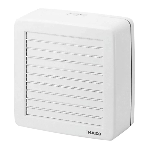
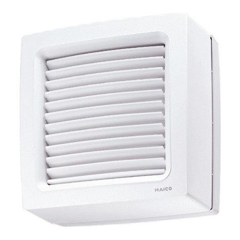
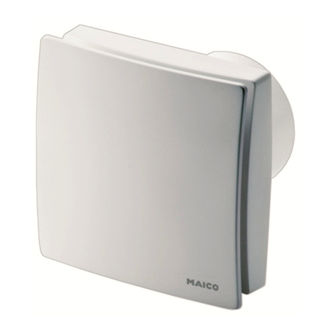
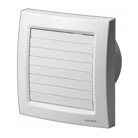
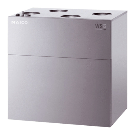
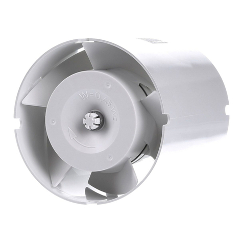
Maico EFR Series Service manual

D
GB
Flachbox
Flatbox
EFR 10
EFR 10 R
EFR 12
EFR 12 R
Montage- und Betriebsanleitung
Mounting and operating instructions
www.maico-ventilatoren.com

2
Flachbox EFR ..
1. Lieferumfang
EFR..-Flachbox mit Ventilatoreinheit und
Montagebügel, Zubehörbeutel mit elektri-
scher Steckverbindung, Montage- und
Betriebsanleitung.
2. Verwendete Warnsymbole
GEFAHR
Lebensgefahr!
Eine Nichtbeachtung kann
zum Tod oder zu schweren
Körperverletzungen führen.
WARNUNG
Verletzungsgefahr!
Eine Nichtbeachtung kann zu
schweren Körperverletzungen
führen.
VORSICHT
Verletzungsgefahr! Sach-
schäden!
Eine Nichtbeachtung kann zu
leichten bis mittleren Körper-
verletzungen oder Sachschäden
führen.
3. Produktinformationen
Geräteübersicht, Abb. A
1 Gehäuse
2 Rändelschraube
3 Montagebügel
4 Anschlussstutzen ausblasseitig
5 Richtungspfeil Luftströmung
6 Gehäusedeckel mit Ventilator
7 Anschlusskastendeckel mit Schaltbild
(Innenseite)
8 Wahlschalter Lüftungsstufe 1...4
(nur „R“-Geräte)
9 Anschlussstutzen ansaugseitig
10 Stecker
T Typenschild
Impressum
© MAICO Elektroapparate-Fabrik GmbH.
Originalanleitung. Druckfehler, Irrtümer und
technische Änderungen vorbehalten.
D

3
Produktbeschreibung
EFR 10 und EFR 12, saugt verbrauchte Luft,
Gerüche oder Feuchtigkeit aus Wohn- oder
Geschäftsräumen ab. Ventilator läuft ständig
in Betriebsart Grundlüftung. Ein/Aus mit
Lichtschalter oder separatem Schalter (beide
bauseitig).
EFR 10 R und EFR 12 R mit 5 Lüftungs-
stufen und Timer. Für den Dauerbetrieb.
EFR.. saugt verbrauchte Luft, Gerüche oder
Feuchtigkeit aus Wohn- oder Geschäfts-
räumen ab.
Grundlüftung: Ventilator läuft in der Regel in
Betriebsart Grundlüftung. Leistungsstufe der
Grundlüftung mit Wahlschalter (4-stufig)
einstellbar.
Intensivlüftung: Ein/Aus der Betriebsart
Intensivlüftung mit Lichtschalter oder
separatem Schalter (beide bauseitig).
Intensivlüftung mit maximaler Leistung
(Stufe 5). Ventilator schaltet auf Grundlüftung
zurück, wenn nach Betätigen des Schalters
die Nachlaufzeit (Einstellwert am Timer,
Einstellbereich 3...25 Minuten) abgelaufen ist.
Ein/Aus des Ventilators mit separatem
Schalter (bauseitig).
4. Technische Daten
Siehe Typenschild.
Abmessungen und Gewicht
Tab. 1: Abmessungen (in mm)
●EFR..: 5 kg
Spannungsversorgung
●Bemessungsspannung: 230 V
●Netzfrequenz: 50 Hz
●Stromaufnahme: 0,27 A
Lüftungsstufen, Volumenströme
EFR 10: 172 m³/h
EFR 10 R:
1 = 95 m³/h, 2 = 112 m³/h, 3 = 134 m³/h
4 = 156 m³/h. 5 = 172 m³/h, Maximalwert
bei Intensivlüftung (Timer Ein).
EFR 12: 208 m³/h
EFR 12 R:
1 = 118 m³/h, 2 = 135 m³/h, 3 = 160 m³/h
4 = 183 m³/h. 5 = 208 m³/h, Maximalwert
bei Intensivlüftung (Timer Ein).
Schutzart
●IP 20 (Staubschutz, kein Wasserschutz)
bei Einbau in Rohrleitungen mit mindestens
1 m Rohr auf der Saug- und Druckseite.
Umgebungsbedingungen und
Grenzen für Betrieb
●Zulässige Umgebungstemperatur:
max. +50 °C
●Zulässige Höchsttemperatur des Förder-
mediums: +50 °C
●Bei Betrieb mit raumluftabhängigen
Feuerstätten muss für ausreichende
Zuluftnachströmung gesorgt werden.
Die maximal zulässige Druckdifferenz
pro Wohneinheit beträgt 4 Pa.
5. Grundlegende
Sicherheitshinweise
Allgemeine Sicherheitshinweise
●Sicherheitshinweise vor Inbetriebnahme
aufmerksam durchlesen.
●Anleitung aufbewahren.
●Montage, elektrischer Anschluss und
Reparaturen nur durch Elektrofachkräfte
zulässig.
●Gerät nur an einer fest verlegten elektri-
schen Installation anschließen!
– Zulässiger Leitungsquerschnitt maximal
1,5 mm².
– Vorrichtung zur Trennung vom Netz mit
mindestens 3 mm Kontaktöffnung je Pol
erforderlich.
D

4
●Gerät nur mit auf Typenschild angegebener
Spannung und Frequenz betreiben.
●Gerät nur komplett montiert betreiben.
●Veränderungen und Umbauten am Gerät
sind nicht zulässig und entbinden MAICO
von jeglicher Gewährleistung und Haftung.
Bestimmungsgemäße Verwendung
●Entlüftung von Wohn- oder Geschäfts-
räumen, Küchen etc.
●Für den Einsatz in Entlüftungsanlagen in
Haupt-Rohrleitung (Einzelrohr).
●Zur Wand- oder Deckenmontage, Aufputz,
in Innenräumen.
●Leitungseinführung Aufputz.
Nicht zulässiger Betrieb
Gerät auf keinen Fall einsetzen:
●zur Förderung fetthaltiger Luft.
●Bei verstopften Ansaug- oder Abluft-
öffnungen oder verstopften
Leitungssträngen.
●in der Nähe von brennbaren Materialien,
Flüssigkeiten oder Gasen.
●zur Förderung von Chemikalien,
aggressiven Gasen oder Dämpfen.
●in explosionsgefährdeten Bereichen.
Sicheres und korrektes Verhalten für
den Betrieb
●Verletzungsgefahr! Keine Gegenstände in
das Gerät hineinstecken!
●Gefahr durch sich drehendes Flügelrad!
Nicht zu nahe an das Gerät gehen, damit
Haare, Kleidung oder Schmuck nicht in das
Gerät hineingezogen werden können.
●Das Gerät ist nicht dafür bestimmt, durch
Menschen benutzt zu werden, deren
physische, sensorische oder geistige
Fähigkeiten nicht genügen, die
Sicherheitshinweise dieser Anleitung zu
verstehen und umzusetzen. Diese
Einschränkung bezieht sich auch auf
Kinder.
Das Gerät kann dennoch von diesen
Menschen gefahrlos benutzt werden,
sofern sie von einer für ihre Sicherheit
zuständige Person beaufsichtigt oder in
geeigneter Weise unterwiesen werden.
●Das Gerät darf nicht als Spielzeug
verwendet werden. Kinder sollten
beaufsichtigt werden um sicherzustellen,
dass sie nicht mit dem Gerät spielen.
6. Montagevorbereitung
Hinweise
●Einbaulage beliebig.
●IP 20 nur bei Einbau in Rohrleitungen mit
mindestens 1 m Rohr auf der Saug- und
Druckseite.
●Nur an Wänden, Decken oder Konsolen mit
ausreichender Tragfähigkeit anbringen.
Montageort festlegen. Ausreichend
Abstand zur Wand/Decke berücksichtigen.
Revisionsöffnung für Anschlusskasten und
Ventilatoreinheit einplanen.
Netzleitung zum Montageort fest verlegen.
An der EFR-Flachbox beide Rändelschrau-
ben [2] lösen und Montagebügel [3]
abnehmen.
Rohrleitungen vorbereiten
Hinweise
●Empfohlen sind Wickelfalzrohre mit einem
Durchmesser DN 100 oder DN 125, je
nach Gerätetyp.
●Nur zum Nenndurchmesser passende
Wickelfalzrohre verwenden.
●Zur Vermeidung von Schwingungsüber-
tragungen auf das Rohrsystem die Rohr-
leitungen mit elastischen Manschetten mit
dem Rohrventilator verbinden, z. B. mit
Maico-ELR.
●Bei Betrieb in staubhaltiger Umgebung
Luftfilter in die Rohrleitung einbauen,
z. B. Maico-TFE.
i
i
D
5
7. Montage
Einbau
EFR-Flachbox möglichst schwin-
gungsentkoppelt zum Rohrsystem
montieren, z. B. mit elastischer
Manschette Maico-ELR und
Schwingungsdämpfern.
Im Bereich des Montageortes für einen
ebenen Untergrund sorgen.
Montagebügel auflegen und Position der
4 Bohrungen anzeichnen.
Bohrungen anbringen und Befestigungs-
dübel einstecken.
WARNUNG
Verletzungsgefahr durch
unzureichende Befestigung
der EFR-Flachbox!
Ausreichend dimensioniertes
Befestigungsmaterial
bereitstellen.
Montagebügel fest mit der Wand/Decke/
Konsole verschrauben (geeignetes
Befestigungsmaterial bauseitig
bereitstellen).
EFR-Flachbox in die Aussparungen des
Montagebügels einsetzen und befestigen.
Beide Rändelschrauben fest anziehen.
Passende Wickelfalzrohre montieren.
Sicherstellen, dass Rohrleitungen beim
Einbau nicht verspannt werden.
Elektrischer Anschluss
GEFAHR
Lebensgefahr durch
Stromschlag!
Netzsicherung ausschalten!
Warnschild gegen versehent-
liches Wiedereinschalten
anbringen.
VORSICHT
Kurzschlussgefahr bei
falscher Einführung der
Netzleitung in den
Anschlusskasten!
Netzleitung ordnungsgemäß in
den Anschlusskasten führen.
Bei Leitungszuführung 90° für
Zugentlastung sorgen
(Zugentlastung bauseitig
bereitstellen).
Anschlussleitung zwischen Netz und
Anschlusskasten muss fest verlegt
sein.
Anschlusskastendeckel entfernen.
Eine der beiden Sollbruchstellen aus der
Wandung des Anschlusskastens
heraustrennen, siehe Pfeil.
Bei 90°-Leitungszuführung für Zugent-
lastung sorgen.
Netzleitung abmanteln und in den
Anschlusskasten einführen.
VORSICHT
Kurzschluss durch Nässe bei
nicht ordnungsgemäßer
Einführung der Netzleitung!
Netzleitung ordnungsgemäß
einführen.
Stecker [10] anschließen, siehe Stecker-
aufdruck und Schaltplan auf Seite 12.
Stecker [10] auf die Steckverbindung
aufstecken.
Netzleitung verlegen, siehe Abbildung
Schaltplan im Anschlusskasten.
i
i
D

6
Für EFR .. R-Flachbox an Potentiometer
[11] die Nachlaufzeit einstellen.
Einstellbereich 3...25 Minuten.
Anschlusskastendeckel anbringen.
EFR .. R-Flachbox: Mit Wahlschalter [8]
die gewünschte Lüftungsstufe einstellen.
Inbetriebnahme
Vor Inbetriebnahme alle Systemkompo-
nenten gemäß deren Betriebsanleitungen
installieren.
Übereinstimmung mit den technischen
Daten kontrollieren, siehe Typenschild.
Vor Inbetriebnahme sicherstellen, dass
sich keine Gegenstände, Kleinteile,
Verunreinigungen etc. in den Rohrleitungen
befinden.
Netzsicherung einschalten.
Funktionstest durchführen.
8. Instandhaltung
Das Gerät ist wartungsfrei.
9. Störungsbehebung
●Bei jeder Störung Elektrofachkraft
hinzuziehen!
●Reparaturen sind nur durch Elektrofach-
kräfte zulässig!
GEFAHR
Lebensgefahr, Gerät steht
unter Spannung!
Netzsicherung ausschalten!
Störung Maßnahme
Gerätestillstand Prüfen, ob die
Netzsicherung
eingeschaltet ist.
Thermischer
Überlastungs-
schutz schaltet
Gerät aus.
Ein/Aus-Schalter
(bauseitig) in Position
„Aus“ schalten.
Vor Wiederinbetriebnahme
Gerät so lange
ausgeschaltet lassen, bis
Motor und Temperatur-
begrenzer abgekühlt sind.
Die Abkühlzeit kann bis zu
30 Minuten betragen.
Gerät erst dann wieder
einschalten.
Besteht die Störung
weiterhin, Elektrofachkraft
hinzuziehen.
Ablagerungen am
Flügelrad und im
Gehäuse durch
staubhaltige Luft.
Fachkraft hinzuziehen.
Luftfilter in Rohrsystem
einbauen.
Innenraum auf keinen Fall
mit Wasser oder Hoch-
druckreiniger reinigen!
Tab. 2: Störungsbehebung
10. Entsorgung
Die Demontage ist nur durch
Elektrofachkräfte zulässig!
Nicht in den Restmüll !
Das Gerät enthält teils wiederver-
wertbare Stoffe, teils Substanzen,
die nicht in den Restmüll gelangen
dürfen.
Entsorgen Sie das Gerät nach Ablauf
seiner Lebensdauer nach den für Sie
geltenden Bestimmungen.
i
i
D

7
Flatbox EFR ..
1. Scope of delivery
EFR.. Flatbox with fan unit and mounting
bracket, accessories bag with electrical plug
connections, Mounting and Operating
Instructions
2. Warning symbols used
DANGER
Danger to life.
Non-observance can lead to
death or serious bodily injuries.
WARNING
Danger of injury.
Non-observance can lead to
serious bodily injuries
CAUTION
Danger of injury.
Property damage.
Non-observance can lead to
minor or more serious bodily
injuries or property damage.
3. Product information
Equipment overview, Figure A
1 Housing
2 Knurled thumb screw
3 Mounting bracket
4 Connection couplings on the exhaust air
side
5 Arrow to show direction of air flows
6 Housing cover with fan
7 Terminal box cover with wiring diagram
(on the inside)
8 Selector switch for ventilation levels 1…4
(only with “R” units)
9 Connection coupling on the intake side
10 Plug
T Rating plate
A
cknowledgements
© MAICO Elektroapparate-Fabrik GmbH. This
instruction is a translation of the German original
operating instructions. We cannot be held
responsible for mistakes or printing errors and
retain the right to make technical modifications
without
g
ivin
g
p
rior notice.
GB

8
Product description
EFR 10 and EFR 12 extract stale air, odours
and humidity from living areas or offices. In
Basic ventilation operating mode, the fan runs
all the time. Fan is switched on/off with light
switch or separate switch, both to be supplied
by the customer.
EFR 10 R and EFR 12 R with 5 ventilation
levels and a timer. Designed for continuous
operation. EFR.. extracts stale air, odours
and humidity from living areas or offices.
Basic ventilation: Normally, the fan runs in the
Basic ventilation operating mode. Basic
ventilation performance level is adjustable
with selector switch (4 levels).
Intensive ventilation: Intensive ventilation
operating mode can be switched on/off with
light switch or separate switch, both to be
supplied by the customer. Intensive ventila-
tion with maximum performance (level 5).
After operating the switch, the fan switches
back to Basic ventilation, once the overrun
time, (adjustable through the timer between 3
and 25 minutes), has elapsed. Fan is
switched on/off with a separate switch, to be
supplied by the customer.
4. Technical Data
See rating plate.
Dimensions and weight
Fig. 1: Dimensions (in mm)
●EFR..: 5 kg
Power supply
●Rated voltage: 230 V
●Power frequency: 50 Hz
●Current input: 0.27 A
Ventilation levels, Volumetric flows
EFR 10: 172 m³/h
EFR 10 R:
1 = 95 m³/h, 2 = 112 m³/h, 3 = 134 m³/h
4 = 156 m³/h. 5 = 172 m³/h, maximum value
with intensive ventilation (timer on).
EFR 12: 208 m³/h
EFR 12 R:
1 = 118 m³/h, 2 = 135 m³/h, 3 = 160 m³/h
4 = 183 m³/h. 5 = 208 m³/h, maximum value
with intensive ventilation (timer on).
Degree of protection
●IP 20 (protected against dust but not water)
when installed in ducts with at least 1 m of
duct on the suction and pressure sides.
Environmental conditions and operating
limits
●Permitted ambient temperature:
max. +50° C
●Maximum permitted temperature of the air
medium: +50° C
●Sufficient supply air intake must be en-
sured during operation with air-ventilated
fireplaces. The maximum permitted
pressure difference per living unit is 4 Pa.
5. Essential safety instructions
General safety instructions
●Read the safety instructions through
carefully before commissioning.
●Keep the instructions.
●Installation, electrical connections and
repairs only permitted when carried out
by trained specialists.
GB

9
●Only connect the unit to a permanent
electrical installation.
– Permitted cable cross-section 1.5 mm²
– Mains isolation device required with
contact openings of at least 3 mm at each
pole.
●The fan unit may only be operated using
the voltage and frequency shown on the
rating plate.
●Only operate the fan unit when it is
completely installed.
●Modifications and alterations to the unit are
not permitted and release MAICO from any
guarantee obligations and liability.
Intended use
●Air extraction from living rooms, offices,
kitchens, etc.
●For use in air extraction systems in main
duct (single duct).
●For indoor, surface-mounted wall or ceiling
installation.
●Surface-mounted cable feed.
Non-permitted operation
The fan unit should not be used:
●For conveying greasy air.
●If the intake or exhaust air openings or
ducts are blocked.
●Close to flammable materials, liquids or
gasses.
●For the conveying of chemicals, aggressive
gases or vapours.
●In areas subject to explosion hazards.
Safe and correct practices during
operation
●Danger of injury. Do not insert any objects
in the unit.
●Danger from rotating impeller. Do not get
too close to the unit, to avoid hair, clothing
or jewellery being drawn into the unit.
●The device is not intended to be used by
persons whose physical, sensory or mental
abilities are not sufficient to allow them to
understand and implement the safety
advice contained in this document. This
restriction also applies to children.
The device can nevertheless be used by
such persons without risk, as long as they
have received suitable instruction or have
been instructed by someone who is
responsible for their safety.
●The device should not be used as a toy.
Children should be supervised to ensure
that they do not play with the appliance.
6. Installation preparation
Notes
●Any installation position.
●IP 20 degree of protection only when
installed in ducts with at least 1 m of duct
on the suction and pressure sides.
●Only install on walls, ceilings or brackets
with sufficient load-bearing capacity.
Decide on the installation location. Make
sure there is sufficient space to the wall/
ceiling.
Make provision for a service opening for
the terminal box and fan unit.
Lay a permanent power cable to the
installation location.
Loosen both knurled thumb screws [2] at
the EFR Flatbox and remove the mounting
bracket [3].
Duct preparation
Notes
●Folded spiral-seams ducts with a diameter
DN 100 or DN 125 are recommended,
depending on the unit type.
●Only use folded spiral-seams ducts that
match the nominal diameter.
i
i
GB

10
●Connect the ducting to the duct fan using
flexible cuffs, e.g. MAICO ELR, in order to
prevent the transmission of vibrations to
the duct system.
●Install an air filter, e.g. MAICO TFE if
operating the unit in a dusty environment.
7. Installation
Installation
As far as possible, install the EFR-
Flatbox such that there is no transfer
of vibrations to the ducting system,
e.g. by using MAICO ELR flexible
cuffs and vibration dampers.
Make sure there is a level surface at the
installation location.
Position the mounting bracket and mark
the locations of the four holes that have
to be drilled.
Drill the holes and insert fixing plugs.
WARNING
Danger of injury caused by
inadequate mounting of the
EFR Flatbox.
Make sure you use mounting
material, which is sized for the
purpose.
Bolt or screw the mounting bracket to the
wall/ceiling/bracket using suitable mounting
material to be supplied by the customer.
Insert the EFR Flatbox in the cut-outs in the
mounting bracket and fix it in place. Tighten
both knurled thumb screws.
Install suitable folded spiral-seams duct.
Make sure that the ducting is not twisted
during installation.
Electrical connection
DANGER
Danger to life from electric
shock
Switch the mains fuse off.
Position a warning notice to
avoid the unit being
accidentally switched back on.
CAUTION
Danger of short-circuits
through incorrect feeding of
the power cable into the
terminal box.
Feed the power cable into the
terminal box correctly.
Make sure there is tension
relief in the case of a 90°
cable feed. Tension relief to
be supplied by the customer.
The cabling between the power and
the terminal box must be permanent.
Remove the terminal box cover.
Separate out one of the two knockout
points on the wall of the terminal box (see
arrows).
Make sure there is tension relief in the case
of a 90° cable feed.
Strip the insulation off the power cable and
feed it into the terminal box.
CAUTION
Danger of short-circuits
caused by damp if the power
cable is not inserted correctly.
Insert the power cable
correctly.
Connect plug [10]. See printed label on the
plug and the wiring diagram on Page 12.
Locate plug [10] on the plug connection.
Lay the power cable. See wiring diagram in
the terminal box.
i
i
GB

11
Adjust the overrun time for the EFR .. R
Flatbox at the potentiometer [11]. Setting
range is 3…25 minutes.
Put the cover back on the terminal box.
EFR .. R Flatbox: Adjust the required
ventilation level with the selector switch [8].
Start-up
Install all system components in
accordance with their Operating
instructions before starting up.
Check that the technical data has been
adhered to, by reference to the rating plate.
Before start-up, ensure that there are no
objects, small parts, dirt, etc., in the ducts.
Switch the mains fuse on.
Carry out a function test.
8. Maintenance
The unit is maintenance-free.
9. Fault rectification
●Call on the services of a trained
electrician any time there is a fault.
●Repairs should only be carried out by a
trained electrician.
DANGER
Danger to life. Unit is powered
up.
Switch the mains fuse off.
Fault Countermeasure
Unit doesn’t run Check that the mains fuse
is switched on.
Thermal overload
protection
switches the unit
off.
Put the customer-supplied
on/off switch to the “off”
position.
Let the motor and the
temperature limiter cool
down before switching the
unit back on. Cool-down
time can be up to 30
minutes. Then switch the
unit back on.
If the fault still continues,
call on the services of a
trained electrician
Deposits on the
impeller and in
the housing
caused by dust in
the air.
Call on the services of a
trained specialist.
Install an air filter in the
ducting.
Under no circumstances
should the inside of the
unit be cleaned with water
or a high-pressure cleaner.
Fig. 2: Fault rectification table
10. Disposal
Dismantling should only be carried out
by a trained electrician.
Not in domestic waste.
The unit contains in part material that
can be recycled and in part
substances that should not end up as
domestic waste.
Dispose of the unit once it has reached the
end of its working life according to the
regulations valid where you are.
i
i
GB

12
Schaltbilder / Wiring diagrams
EFR 10, EFR 12
EFR 10 R, EFR 12 R
Maico Elektroapparate-Fabrik GmbH • Steinbeisstr. 20 • 78056 Villingen-Schwenningen •
RLF.1_01.11_DSW_eli
GB
D
This manual suits for next models
4
Table of contents
Languages:
Other Maico Fan manuals

Maico
Maico AS 20 User manual

Maico
Maico EN 20 Service manual

Maico
Maico ECA piano Service manual

Maico
Maico ECA 120 User manual

Maico
Maico ERV 120 User manual

Maico
Maico EHD 10 EC Service manual

Maico
Maico EVN 15 Service manual

Maico
Maico AWV 10 Service manual

Maico
Maico EKR 20-2 Service manual

Maico
Maico EZQ B Series User manual

Maico
Maico PPB 30 O Setup guide

Maico
Maico ERM 18 E Ex e User manual

Maico
Maico PushPull PP 45 RHK User manual

Maico
Maico ECA piano STANDARD Service manual

Maico
Maico GRD 22 Service manual

Maico
Maico DAS 71/4 Service manual

Maico
Maico R10 User manual

Maico
Maico AE 10/1 User manual

Maico
Maico PP 45 O User manual

Maico
Maico ERK 100 ST Service manual