MAKE A WAKE MARINE ADVANCER TOWER User manual

ADVANCER TOWER INSTALLATION MANUAL
EXPLODED VIEW OF THE TOWER FOR REFERENCE
STEP 1:
Unpack and check the contents of the box. Check the parts list and the Instruction Guide
correspond with the product you purchased. Ensure you have the correct tools to complete the
Installation. If you do not have the skills to complete the installation hire someone who can install
for you. Please Read all Instructions prior to starting installation. If you are NOT sure of any part of
the guide or you have any questions, please contact us. Email: sales@makeawakemarine.com
VERY%IMPORTANT%NOTE:!
1.#Please%remove%the%rubber%caps%of%each%leg,%it%is%packaging%material%which%MUST%NOT%be%used%
for%installation,%or%it%will%lower%the%tower%strength.!

2. Please DO NOT remove the plastic sleeves inserted in the H top section, they can prevent
scratching when you insert tower arms into the top section.

PARTS LIST
STEP 2:
Attaching the end fittings to long curved Front Legs Note there is a left and right front leg. You will
also see that one end has a welded lap joint already. At the opposite end of the front leg insert the
raised circle base of the fitting into the counter sunk area. Use the M12 bolt and split washer
inserted through the center and tighten.

STEP 3:
Attach the front legs to the L shape Elbow sections. The front legs have a Square shaped Lap joint
already welded onto the top end.
Note: There is a Left and Right front leg and a Left and right Elbow L shape also. Attach the lap joint
with the two threaded holes of the front leg to the two open holes of the lap joint of the elbow
section.
Check the shape of the legs are correct. If you are in doubt you can always swap them over and
check.
Step 4: Attaching end fittings to short curved rear legs.
Insert 1 x open hole fitting with the raised circle base of the fitting into the counter sunk area at one
end of the short curved rear leg. Use the M12 bolt and split washer inserted through the center and
tighten. Repeat this to the second rear leg.

At the other end of the rear leg insert 1 x threaded fitting with the raised circle base of the fitting
into the counter sunk area at the end of the short leg. Use the M12 bolt and split washer inserted
through the center and tighten. Repeat this process to the other rear leg.
Step 5: Assembly of Deck Mount Reference
If you have 2x S knuckle joints, please follow below picture, otherwise please follow the next
picture.

Note the shape and the “at base of the deck mount. Note the threaded hole from the bottom of the
base of deck mount.
If you don’t have 2x S knuckles, it means you have a swivel deck mount which doesn’t need
the S knuckles, please follow below picture, and make sure 1. You put the smooth nylon plate
between the metal mount and the deck, 2. It is put on a flat surface. These 2 points can
ensure you fold the tower for storage.


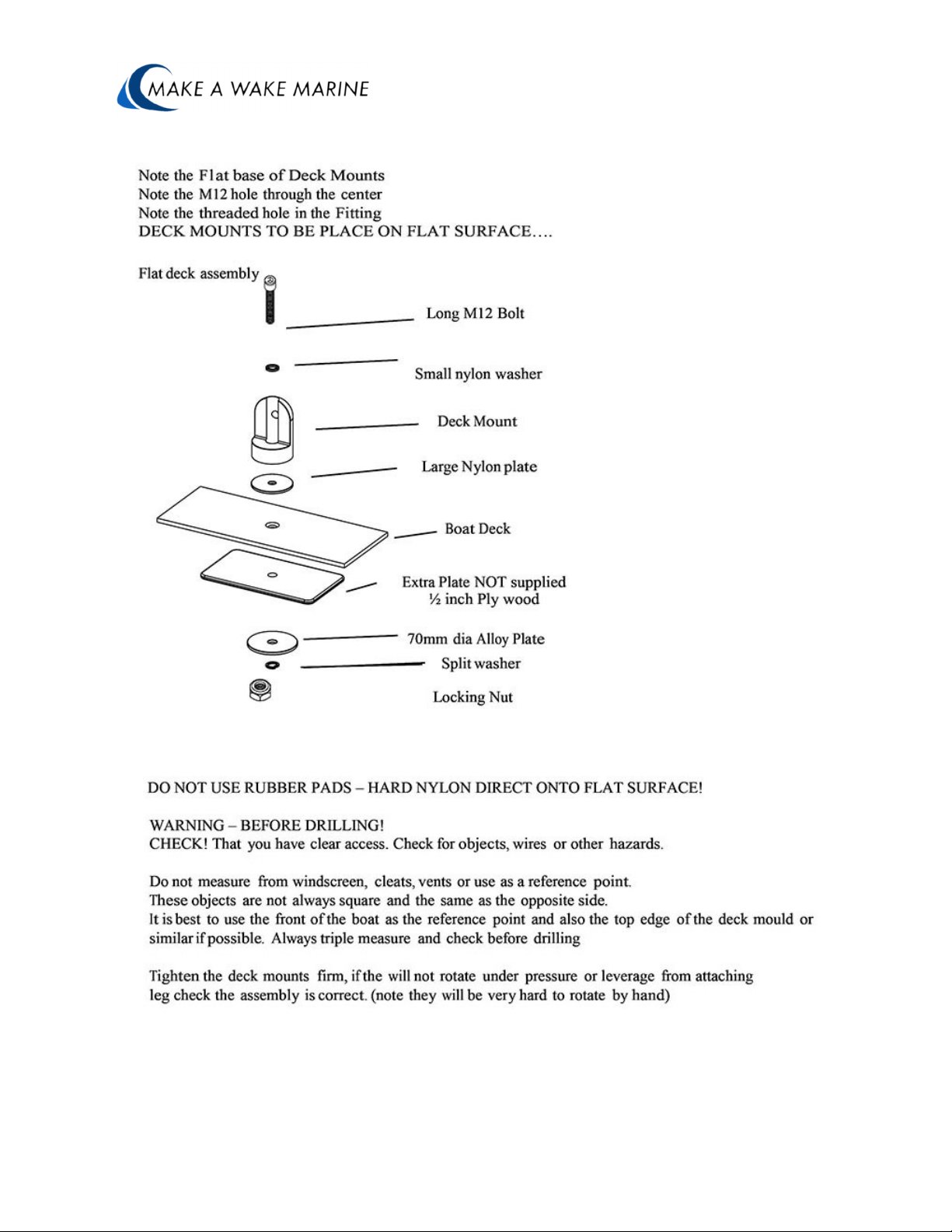
Step 6: Installation of Front Deck Mounts onto Boat.
Distance between Front Mounts across the boat up to 2m wide. We recommend to use an extra
plate of (plywood or Alloy) underneath the deck between the our alloy plate and the hull of the boat.
Spread over the largest possible area to reduce gel coat cracking. WARNING: Check that you have
clear access to the area for drilling and tightening bolts. Check for objects, wires or other hazards
you could damage when drilling. Do not measure from or use windscreens, cleats, vents as a
reference point. These objects are not always square and the same as the opposite side. It is best
to use the front of the boat as the reference point and also the top edge of the deck mold or similar
if possible. Always triple check your measurements, and check before drilling. Tighten the deck
mounts firm but not locked into position as you will still need to rotate and align at a later point
during installation.
Step 6.1: Check the front mount measurements. Measure across the boat the position of your
front.
Place deck mounts in the area you wish to mount. Either in front of the windshield, out to the side
as far as possible or on the angle side of the boat. Check that the measurement is less than 2m
wide. Remember the measurement you have.
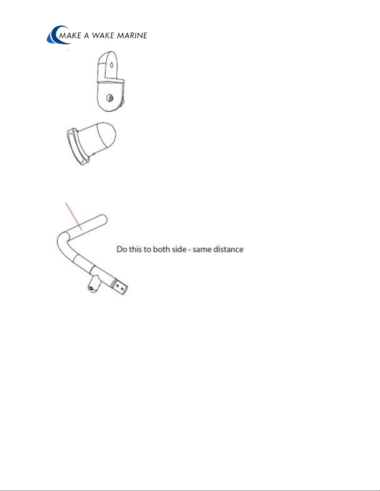
(a) Now built up the front legs and top tube and lay on the ground. Check that the front mounts can
adjust to fit you boat at the distance you require.
Note: for narrow boats you may have to cut the top tube to allow the legs to insert in further for the
correct mounting distance.
TIP: It is a good idea to grab one side leg and hold up against the boat and move forwards and
backwards while someone else stands back to see what looks the best to suit your boat. Mark this
position and then check the other side for objects, wires, etc. before drilling these areas.
(b) Drill and Attach the front deck mounts (refer to assemble diagram). Use the front of the boat as
ref point. Position deck mounts on a “at surface on as close as possible to flat. If on the side,
position as close as possible to the top edge/corner of the deck for the strongest part of the boat
and least amount of flex in the side of the boat. Use small pilot hole first. Drilling in reverse can help
stop chipping gel coat.
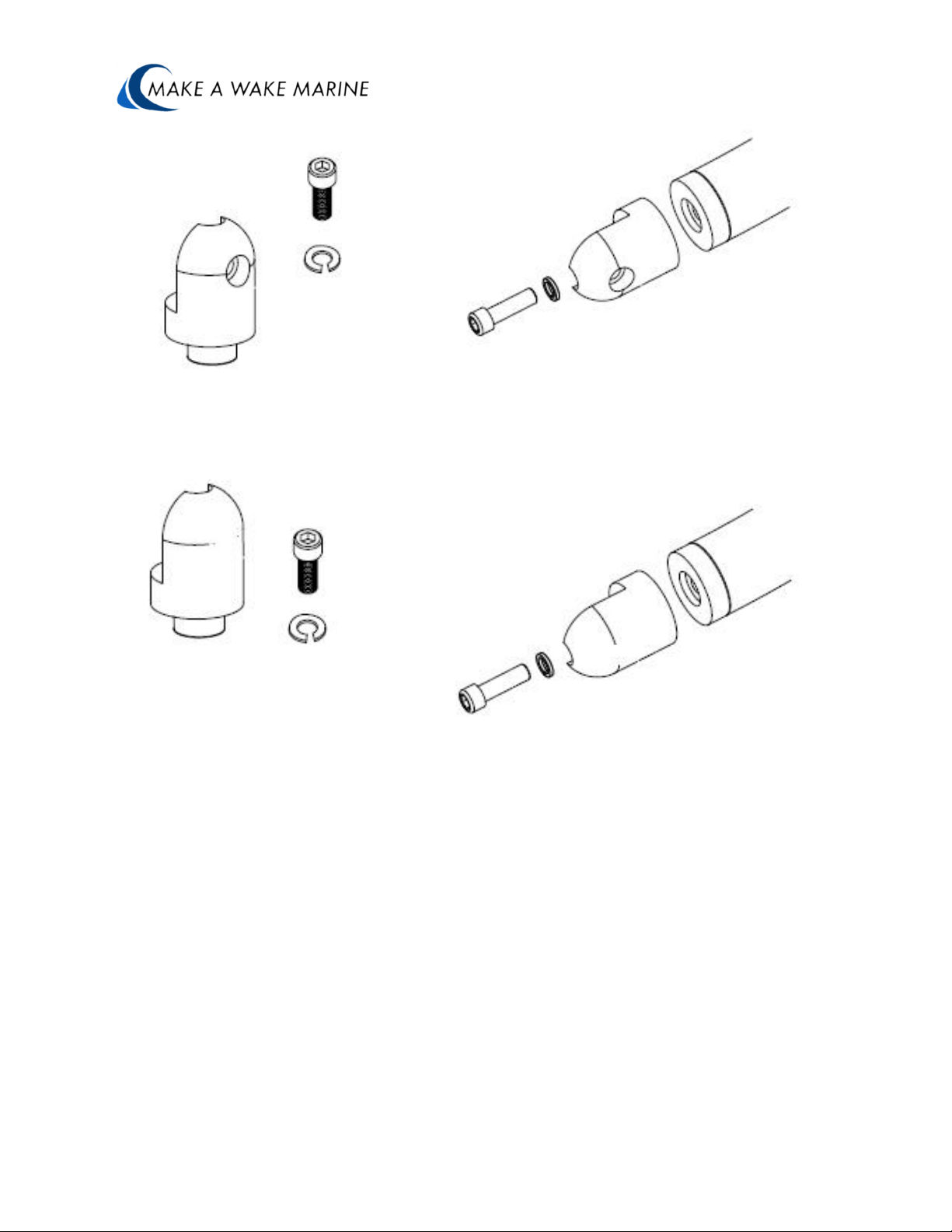
STEP 7: S knuckles assembly
If you have 2x S knuckle joints, you need to attach the knuckle joint to the front deck mounts. You
can play with the deck mounts rotating them so the “at surfaces faces up on one side and down on
the other. Then attach the knuckle joint to the deck mounts. Leave the deck mounts so they can
still slightly rotate under pressure for positioning.
NOTE: There is no left or right knuckle so one deck mount will face forwards the other will face
backwards.
Note again: If you don’t find the S knuckle in your mounting kit, it means you have a swivel
deck mount which doesn’t need the S knuckle.

STEP 8
Attaching the front legs to the deck mounts and telescopic top section. At this stage it is good to
mark you elbow section with a reference mark which will come in handy later. Measure from the
tube end on the elbow towards the corner bend and make a mark or tape.
Step 9: Attaching the tower to the boat.
(I) Attach one of the front legs to the deck mount or knuckle joint. You should be able to
still rotate the deck mount at this time. It should be firm and solid, but not locked into
position.
(b) Lay the front leg down towards the back of the boat.
(c) Now slide the tow point top tube over the elbow section of the front leg. Careful do
not scratch.
(d ) Slide the other front leg into the single top tube and then attach to the front deck
mount.
I Centre the tow point and tape the tube so it does not move and scratch your legs.
(f) Tighten the front deck mounts and knuckle joints. Check you can freely lift and lower
the tower.
Step 10: Attaching the rear deck mounts to the boat.
If you are confident in the positioning of the rear deck mounts and the look you will have.
You can just measure back a distance between 1.5m to 2m from the front deck mounts and follow
the deck mount assemble like the front deck mounts.
or with a couple of friends

Attach one of the rear legs to your tower. Lift the tower and one person can adjust the position of
the rear leg backwards, forwards, up, and down to position you like. You stand back and look from
the side to see what you like the best.
Mark the deck mount position you like. Take measurements mark out the opposite side of the boat.
WARNING: Before drilling check for objects, wires, etc. under the deck where you are going to drill.
INSTALL BY YOURSELF.
You might have to do some guess work with the location of the rear mount. As a guide, 1.75m from
the front and position the mount near the top edge of the deck for the strongest area of the boat.
STEP 11: Once you have the rear legs on the tower, TIGHTEN all the deck mounts from
underneath the deck.
Make sure the front knuckle joints are square so you can pivot and lower the tower from the front.
STEP12: Center and align the tow point to the center of the boat.
NOW you can drill and bolt the top section using the reference marks you made earlier. Have the
tow point vertical or leaning slightly forwards.
STEP 13: Double check everything is in line and looks correct.
Now you can go around to every fitting mark across the fitting to the tube. Once you have marked
all the joints. Remove one fitting at a time, use lock tight on the center bolt and re attach each bolt.
For the bolt you need to loosen to fold do not use lock tight.
CARE AND MAINTENANCE
Be sure to check and tighten all fasteners and connections prior to every use Be cautious when
towing or driving under obstacles, low hanging structures or trees Leave tower in the erect position
when towing behind a vehicle Use soap and water to clean your tower. Always rinse and wipe
down tower after contact with salt (brackish) water. You will have to keep this tower polished to
keep its nice shine. If Powder coated tower wipe and keep clean do not use abrasive materials or
liquids to clean. Check before using cleaning agents on tower.
How to fold the tower
I. Disconnect tower from rear mounts
II. Loosen the front mounts
III. Fold tower back to down position

WARRANTY
Origin warrants the product (not including other 3rd party accessories) against
manufactures defects for 5 years to the Original purchaser/owner.
The product/part maybe requested is to be sent to the Distributor for inspection where it will either
be repaired or replaced. (unless otherwise agreed in writing)
The customer is liable for costs associated in shipping the product/part to Origin Distributor. Origin
is not responsible for personal injury or damage to the boat caused by the use of the tower or any
transport charges or cost of installation or removal of the tower.
Origin is not liability for direct or indirect or consequential damages resulting from delay or improper
installation.
Warranty does not cover anodized, polished and powder coated surfaces as well as any hardware
corrosion. They are excluded as their care and use cannot be controlled by Origin.
Warranty does not cover the spider coat gel cracking or damage from the installation or use of the
tower on your boat. No dealer, retailer or manufacturer is the agent of James G Pty Ltd and may
not assume any liability in connection with this warranty. This warranty is in lieu of all.
IMPORTANT NOTE FOR INSTALLATION

The construction of your boat, design of the deck, thickness of deck and walls and overall design
may cause movement at the mounting points.
If the construction of you boat causes movement at the mounting points or incorrect mounting
location creates added pressure on joints increasing movement of the tower it voids warranty. If in
doubt do not install the tower or seek a professional to install for you.
Always read the warning labeled on the tower prior to each use.
Do not remove warning label from tower.
Table of contents
Other MAKE A WAKE MARINE Boating Equipment manuals
Popular Boating Equipment manuals by other brands

Harken
Harken Crossbow 2758.1.1M.20 instructions

Power-Pole
Power-Pole micro anchor installation manual

Attwood
Attwood 69212T installation instructions

Harken
Harken Carbo Racing Foil instruction manual

Hobie
Hobie Kayak Sail Furler Kit manual

Ideal Windlass
Ideal Windlass CWM Installation, operation & maintenance instructions