MakeKit MD2 Dronekit User manual

1
Teacher and student guide
MD2 Dronekit

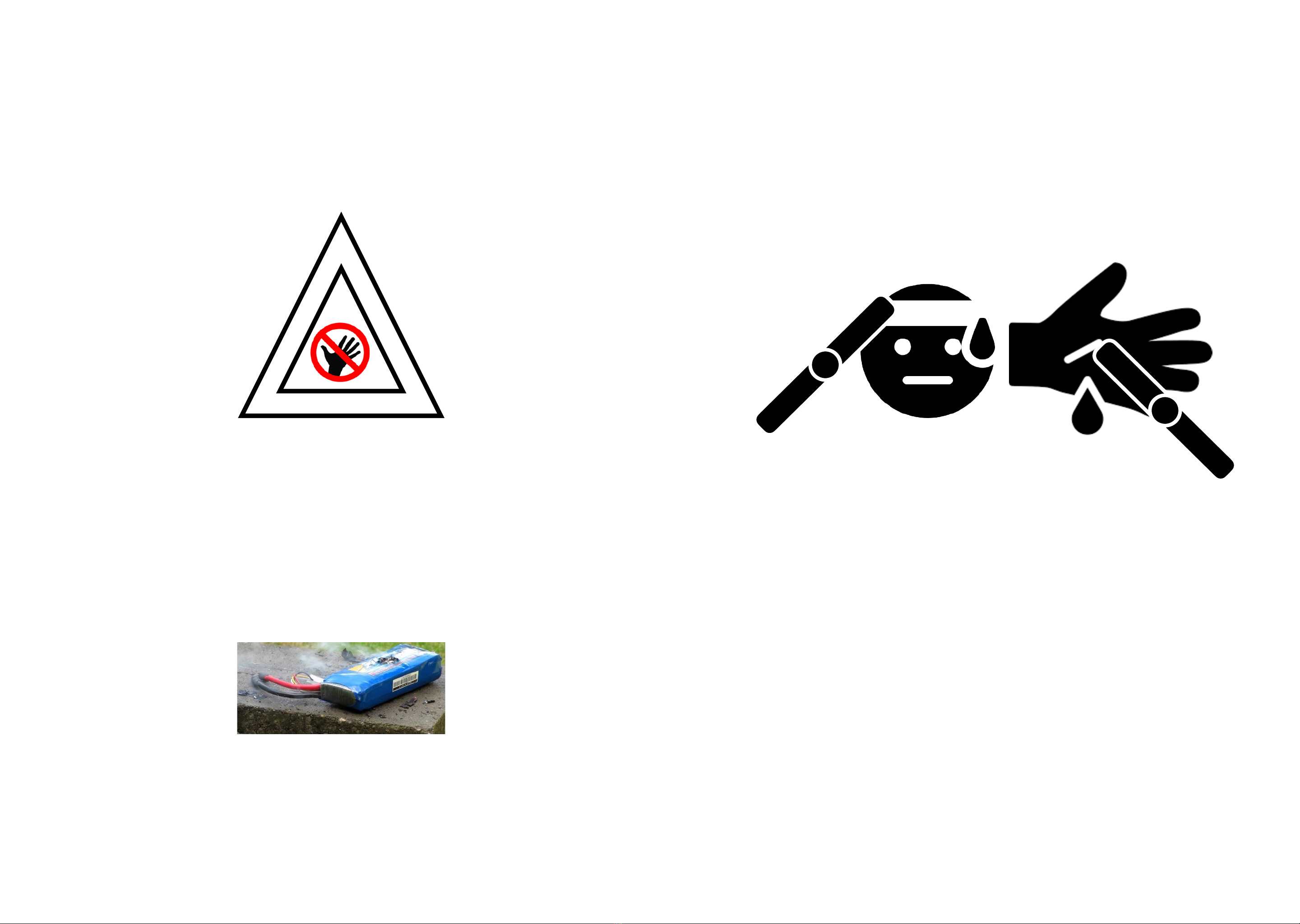
Start by studying the safety information on the next page. Propellers
can cause damage and must therefore be distributed at the end.
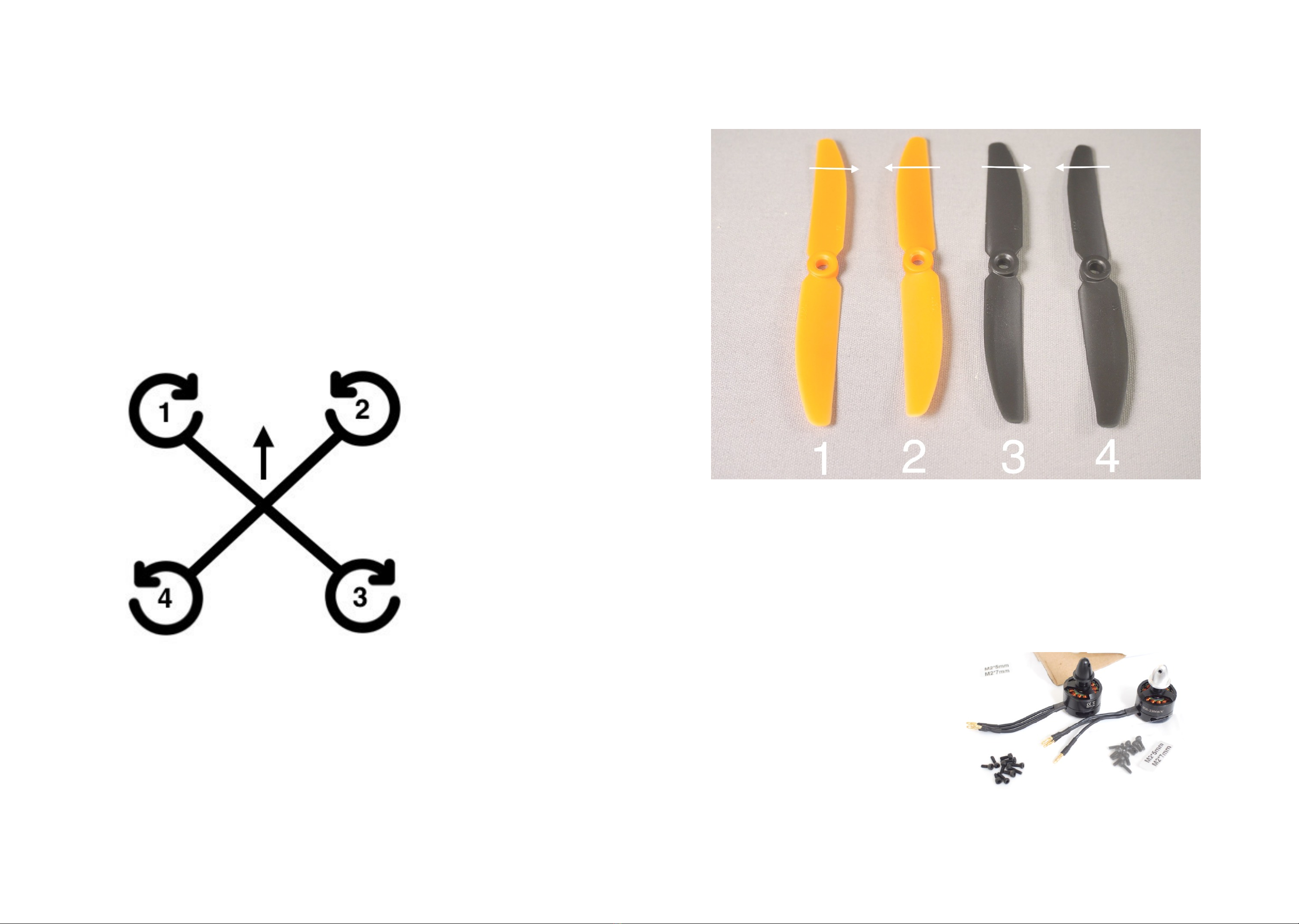
Paper propellers are used temporarily to test that the motors are
going in the right direction.
2
Construction plan:
There are four main areas, which should be done in this order:
assembly, electrical connections, programming and flying. !
You are welcome to delegate the four tasks to different students,
who are each given their own main responsibility, which they can
later roll on (especially the flight).!
Once the drone is built and the electrical connection is made, check
the following before getting the battery:!
Layout, page 8. Silver motor in the right place. Two different colors
of propeller protectors, one at the front and another at the rear.
(Color may vary).!
Wiring diagram, page 15. It is especially important not to switch
between + and - between ESC (speed controllers) and power
distribution boards, as well as not to change the battery measuring
cable and speaker cable.!
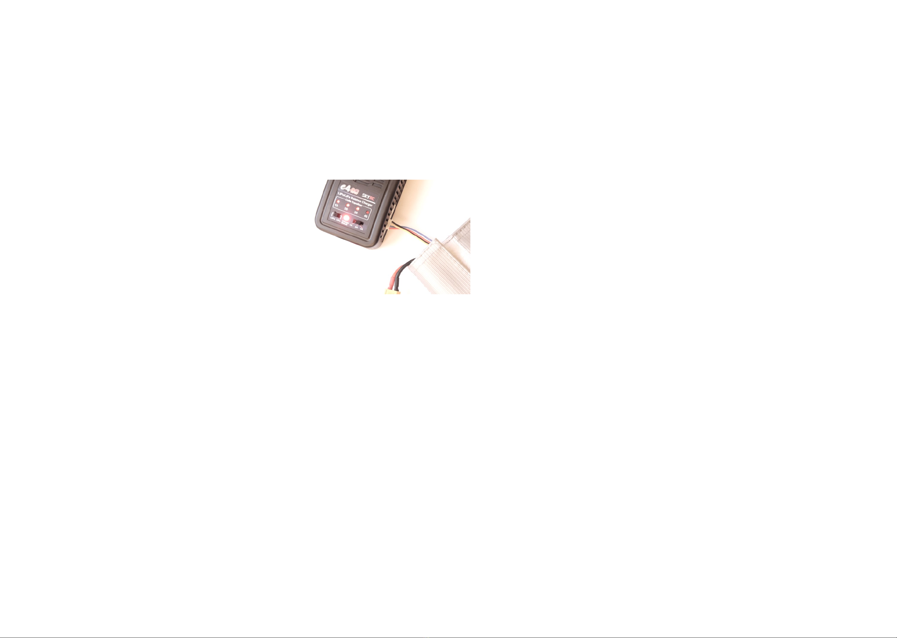
Charge the batteries. Put the battery in the
enclosed charging bag. All lights should be
green before charging is complete after 1-2
hours.!
Insert 4 AA batteries into the radio. We
recommend rechargeable batteries for the sake
of the environment.!
The drone flies for 11-13 minutes on one battery.!
Reset the drone's control card by selecting
“factory reset” which is located at the very
bottom of the menu.!
•When they have finished programming, you or students
(other than those who have programmed) should check the
following:!
•The paper propellers should rotate straight in accordance
with the layout, page 8.!
•Review receiver test, page 18. Check that the movements of
the connectors are correctly reflected on the screen. Throttle
= gas, left stick down = 0, up = about 100!
•Yaw (rudder) = side rotation, left stick to the right / left results
in “rudder left / right” +/- about 100!
•Pitch (elevator), right stick forwards or backwards, +/-
approx. 100!
•Roll (aileron), right stitch to the side, +/- approx. 100!
•Check that all wires and components are attached correctly
and that no wires or antenna can be cut by the propellers.!
•Once this has been checked, you can distribute the
propellers. It is important to distinguish between up and
down, as well as right- and left-rotating propellers. See page
9. Make students aware of the dangers associated with
propellers.!
Flight:
The pilot and the rest of the team take the drone to a suitable
flight area. Gym or other open space indoors is the safest and
is unregulated by FAA and aviation authorities. Avoid third
persons entering the flight area and especially smalle children
must be kept at a safe distance. Low ceiling height can also be
an advantage as you can not crash from a great height.!
Outdoors, large grass pitches are the best place to fly as it is
open, and the surface is soft and damages the drone less in the
event of a crash. Provide the required safety distance to
outsiders. Check local rules regarding flight outdoors.
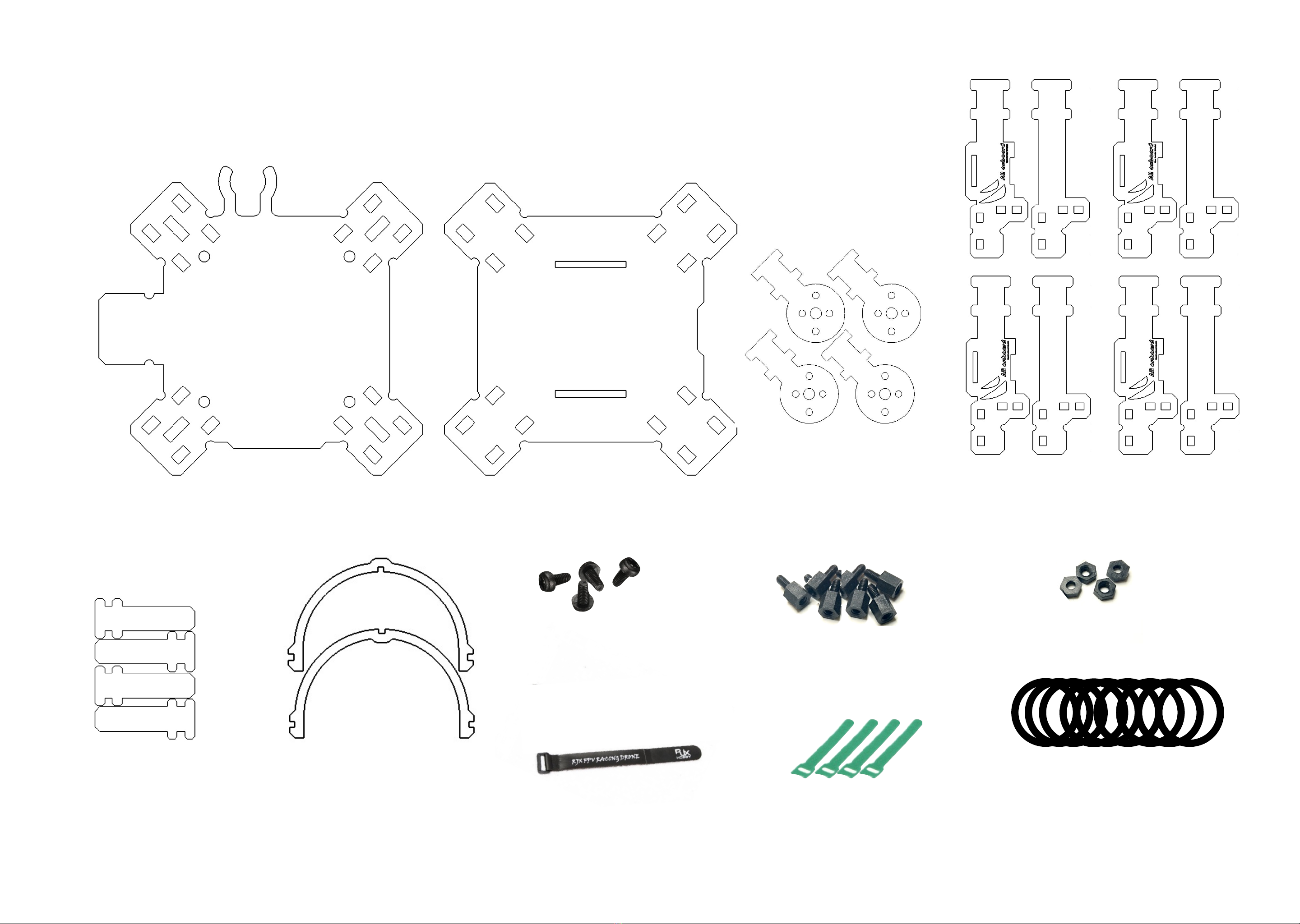
Tools:
1.5mm Allen or Torx. Star puller medium size. Scissors if you
want to cut out paper propellers.!
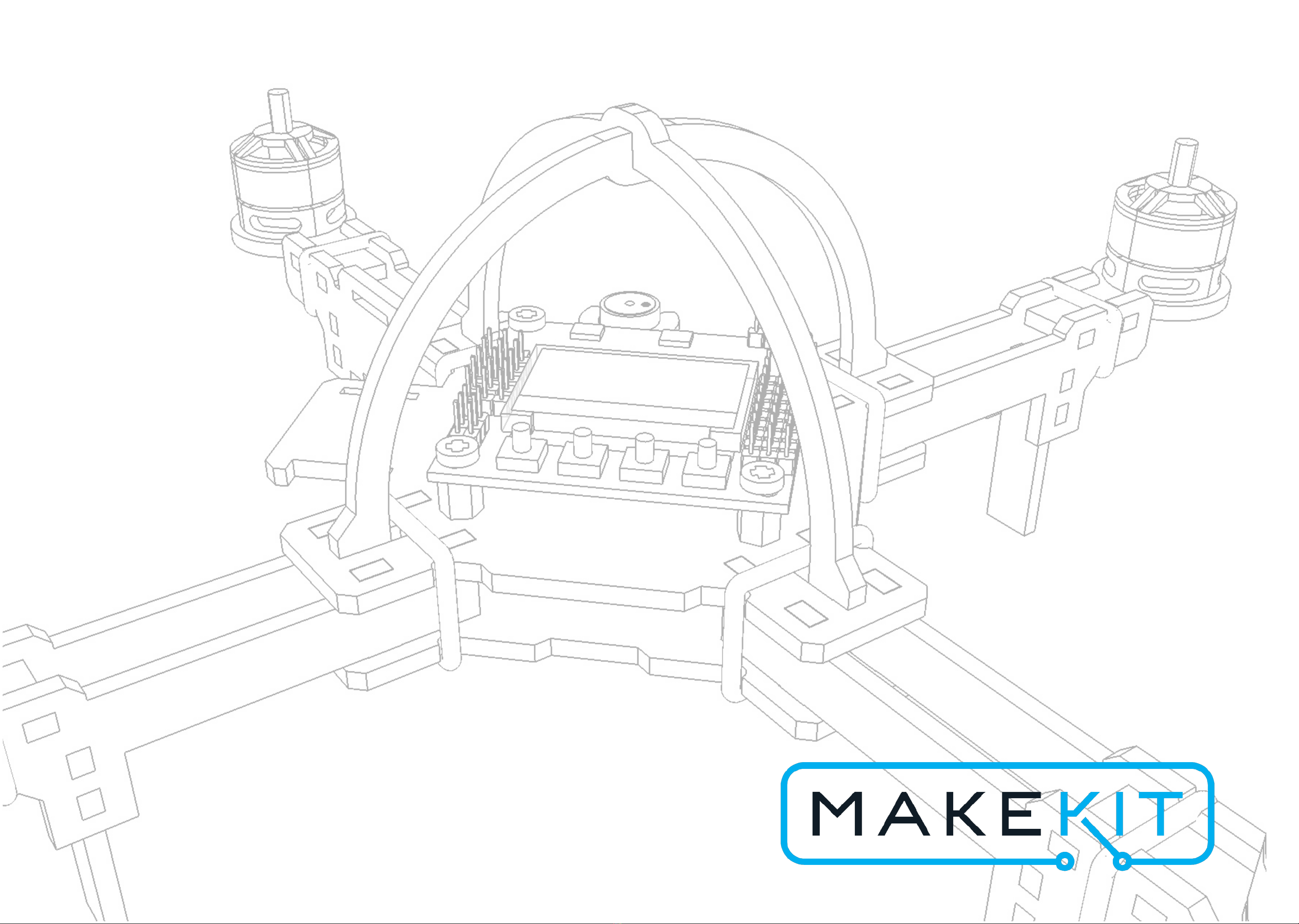
To the teacher

PROPELL
BATTERI
ARMERING
When the drone is armed* and the propellers are
mounted.!
you must have at least 2 meters safety distance to
the nearest person.!
*Arming: The drone is activated and the propellers
can spin. Characteristics: Red light on control card,
it says "ARMED" in the display.!
The drone battery (LiPo), can develop heat and toxic
fumes if it is severely damaged. It the batteri suddenly
inflates or starts to extract smoke, get the battery outside
the premises, and away from people as quickly as
possible. !
Have a plan for this in advance.
Rule 1:
Rule 2:
3
Propeller hazard
The propellers rotate at up to 28,000 rpm. minute.
Show respect for the forces and damage potential of
the propellers when the drone has battery connected.!
Keep the required safety distance when the drone is
armed.
Aviation rules
When flying outdoors, make sure to follow local drone
rules. Keep a safe distance so as not to endanger other
people.
It is not recommended to fly this drone higher than the
roof of the nearest building and no more than 30
meters away from yourself. This will help you retain
control of the drone.
Safety

Deleliste - Ramme
Bottom plate Motor holders,
4x
Nylonnuts,
4x
Nylonskruer,
4 stk
Velcros, 4x o-rings:
8x
Top plate
Protection hoops
upper / lower part
Landing legs Battery strap
Arm pieces,
type A and B, 4 of each
Avstandsstykker,
8 stk
4

Deleliste - Elektronikk
1 x
3 cell LiPo-battery
2+2 1806 2300 kv
brusless motors, CW and
CCW type
1x Power distribution board 1 stk KK2 flight controller
4 servo cables
2+2 propeller, CW
and CCW type
(+4 spares)
1 stk fire proof LiPo
Charging bag
Piezo-speaker with cable
1 stk
Radio with receiver
5
4 x regulators
(ESC)
Receiver

6

Assembly
As assembly manager, your job is to make sure that all the parts are assembled together in
the right way. Use the attached drawings and get a couple of free hands from your team
members.!
You are responsible for all assembly except connection of wires, which is left to a
knowledgeable electrician when your job is done.!
What you need to do:!
•Get the necessary tools: Medium-sized Phillips screwdriver, 1.5mm Allen key, scissors!
•Follow the construction instructions. You will receive parts from the component manager as
you need them. Bring helpers with you, then it might go faster.
7

Layout Sort
motorhode
Black
motor
Silver
motor
Nose
direction
Control board to be
mounted this way!
Clock wise rotating
propeller
Counter clock wise
rotating propeller
Make sure:
You must have two identical colors
on the front of the propeller
protectors, and another color on the
back.!
This is to make the flight easier for
the pilot.!
You must place the black and silver
motor as shown in the picture. The
engines must go their separate ways.!
You must place the top plate as
shown in this picture. The control
board must be placed in the direction
shown here.!
The direction of the nose on the
drone is then to the north.!
Finally, you must mount the right
propeller in the right place. See next
page.
8
Clock wise rotating
propeller
Counter clock wise
rotating propeller
Black
motor
Silver
motor

Mounting the propeller
We recommend saving this part until everything else is mounted.
Always make sure that the battery is disconnected before mounting
the propeller!
Also, make sure that you have tested and adjusted the direction of
rotation so that they are correct.
Unscrew the bolts on top of the engine and place the propeller on the
screw.
Tighten the bolts again. They can be screwed with your fingers and
should not sit particularly hard. They tighten themselves during flight.
Silver motor head should be screwed the opposite way of black motor
head.
9
We have two types of propellers, right and left rotating. (Regardless of
color)
Right-rotating is marked R, eg 5030R. Install the propellers according
to the overview above.
The writing on the propellers is going up towards the sky.
5030R 5030 5030R 5030
Clockwise (CW)
Counter clockwise (CCW)
Clockwise (CW)

Motors and arms
4
Temporarily thread a small rubber ring onto the
motor plate (1). Click the engine plate with armrest
type a and b (2) and the landing legs (3). Finally,
tighten the rubber ring (4).
Repeat for all four arms.
1
3
2
2
Senter plate
2
3
4
5
1
6
Tools: Star puller
Parts:
1 top plate
4 nylon screws
8 spacers
4 nylon nuts
1 control card
1 power distribution board
Note the location of the top plate,
with the holder for the receiver
located on the left (1) and the
holder for the buzzer (2).
Also note the location of the
power distribution board, with the
battery cable facing south (3)
and the thinner battery
measuring cable facing north
(not shown)
Screw the 8 spacers above and
below the top plate (4), fasten
the power distribution board with
4 nuts (5), and finally the control
board with 4 screws (6).
1
2
3
Tools: 1.5mm Allen wrench
Parts: 4 engine plates, 4 engines, 4 propeller
protectors, 8 arm pieces (two variants), 4 landing legs,
16 pcs 10mm m2 screws, 4 o-rings
Screw in all four engine screws through the engine
plate (1), the propeller guard (2) into the engine (3).
NOTE! The screws must pass through both the
engine plate and the propeller guard!
x4
x4
10

Final frame assembly
2
3
4
5
Parts:
1 pre-assembled top plate,
4 pre-assembled arms,
1 bottom plate,
1 battery strap
2 roll bars upper and lower part
4 o-rings
Mount the battery strap on the lower base
plate so that it can hold the battery later (1)
Place a large o-ring on each arm (2) click
together the arms between the top plate (3)
and the bottom plate (4)
click in place lower roll bar (5), then upper
roll bar (6).
Thread the o-rings into place so that they
hold the top and bottom plate together.
Check everything everything fits well
together in the end (7)
6
7
1
Velcro on this
side
11

12

Electrical connections
As an electrician, your job is to connect all the electrical components together correctly.
The components must be connected in the right place, and all plugs must be connected
in the right way.!
Be careful: Faulty connection can lead to malfunction and damage to components,
when connecting the battery.
13

Elektronikkmontering
Parts:
4 pieces of fastening tape
1 radio receiver
1 o-ring
1 piece of elastic
4 servo cables
1 radio receiver
4 servo cables
1 pc buzzer
4 pcs regulators
Mount a fastening strap on each arm (1)
Attach the radio receiver with a large o-ring
(2)
Attach the buzzer to the holder (3)
Thread the antenna through the hole next to
the radio so that it points downwards and
cannot be hit by propellers (4)
Connect regulators, buzzer and power
cables according to the wiring diagram on
the next page.
Attach the regulators along the arms and
tighten the fastening strap around. (5)
You can now pick up the drone battery. This
must be strapped in the middle underneath
the quadcopter
2
3
1
4
14
5

AIL
ELE
THR
RUD
Buzzer/ speaker
Battery measurement
cable
M1
M2
M3
M4
S+-
Radio receiver
Flight direction
-Jord
+5 volt
SSignal
Servo cable: Minus is the darkest color, then red is +5v, then S is the signal (PWM)
Connection diagram
- + S
Buzzer cable
ESC
+ -
- +
LiPo Battery
ESC
Motor
ESC
Motor
ESC
Motor
Motor
ESC
ESC
M2
M1
M3
M4
s + -
4
3
2
1
S - +
RUD
THR
ELE
AIL
Plug
Strømfordelings-
kort
4 x
Servo cables
M1
M2
M3
M4
15
Nose direction - this way
forward

16

Programming
As a programmer, you must make sure that the control card is configured with the
necessary parameters and calibrations that are necessary for the quadcopter to work.
Be careful so that the drone flies stably.
17

Oppstart
Turn on the radio transmitter.
Then connect the power by plugging in the drone battery in the yellow plug. The
control board then starts up and you should hear a beep in the buzzer.
• There should also be a beep every time you press a button.
• If the buzzer does not make a sound, tell the electrician to fix it.
• There may be error messages on the screen, which will disappear later.
• Check that the battery meter works. A full battery is about 12.6 volts. The
display should then say: “Battery: 12.6 volts”
ACC Calibration
We need to calibrate the accelerometer so that the control board knows
where the ground is.
Click “MENU” and “UP / DOWN” until you find this item. Follow the
instructions.
Setup radio receiver
This must be done together with the pilot.
Go to “Receiver Test”. Here it is important that both jacks on the
remote control correspond to the deflections on the screen. Each stick
represents two channels and is called Aileron (Roll), Elevator (Pitch),
Throttle and Rudder (Yaw). It is very important that the movement
detected on the screen is correct. For example, a right movement with
the right stick should result in the effect "Aileron: Right" on the screen.
Check that all four directions of flight are correctly registered by
the control card, both in cases of "left" and "right" as well as
"forward and" backward ".
The throttle should go from about 0 when it is down, to about 100
when it is at max. If this is reversed, you can use the reversal buttons:
Sticks vs screen
18
You should also make sure that the numbers are around 0 (+/-
5), when the sticks are in the neutral position, ie the throttle is in
the lower position, while the others bounce back to their starting
point. The trim buttons are used for this.

Battery alarm
To know when the battery is nearing the end, we must program the
voltage alarm. Go to Misc settings 1 -> Alarm 1/10 volts. Enter 105
(10.5 volts).
Our 3-cell battery will be fully charged at 12.6 volts and completely
empty at 9.9 volts.
Fullt: 12.6 Volt
Helt tomt: 9.9 Volt !
(fare for skade på batteri og drone)
Snart tomt: 10.5 Volt
3 cellers LiPo
batteri
Self-level
Self-level means that the quadcopter returns to a horizontal position when
we release the plugs. Go to Mode settings -> Self-Level: Always
Motor Layout
It is important to let the control card know what kind of multirotor you have.
Navigate to “Load motor layout” and select quadrocopter X mode ”.
You will then get an overview of:
• Location of engines
• Directions of rotation
• Engine number
Check with the electrician if the controllers 1-4 are connected to the correct
output on the control board, according to the wiring diagram (page 14)
Now, together with the pilot, check the direction of
rotation of the engines, one by one.
• Install paper or paper propellers (page 24) on the
motors.
• Arm the drone (see page 23) and gently
accelerate until the engines spin.
• Check if the motors are going in the right
direction. See layout page 6
• If an engine does not spin directly in relation to
the engine layout, the direction must be reversed.
• You do this by switching any two plugs between
motor and regulator.
19

The next thing to do is called the throttle range and is done to calibrate the controllers so
that they interpret the control signals from the control board in the same way. Here you
must be two people. No propeller can be mounted at this stage.
Disconnect the battery on the drone.
Kalibrering av regulatorer
Start by turning on the remote control and set the throttle to max.
Person 1 holds down buttons 1 and 4 on the flight controller at the same
time and holds these until the procedure is completed. Person 2 then
connects the battery on the quadcopter. The screen should show
"Throttle pass trough". Wait about 4 seconds - a beep sounds.
As soon as this signal is complete, immediately lower the
throttles to zero. Wait for a new signal. You can now release
buttons 1 and 4. Restart the quadcopter by pulling out and
inserting the battery again (the radio transmitter is on all the
time).
Verify that all the motors spin up when arming. Propeller should still be off! Gently
accelerate with the throttle. At a certain point, all the motors should start spinning
almost as fast. It is an advantage that the quadcopter stands horizontally on this test.
20
Table of contents
Other MakeKit Educational Equipment manuals
Popular Educational Equipment manuals by other brands

Nasco
Nasco Life/form LF03840U instruction manual

fischertechnik
fischertechnik STEM Coding Pro Assembly instruction

fischertechnik
fischertechnik ROBOTICS ADD ON KI Assembly instruction

SmartMan
SmartMan ALS manual

MindWare
MindWare Crystal Hedgehogs instruction manual

Quanser
Quanser QNET Mechatronic Actuators quick start guide

TTS
TTS Glow Pebbles quick start guide

Enabling Devices
Enabling Devices Turtle Switch 729T user guide

CamJam
CamJam EduKit 3 Assembly instructions

LeapFrog
LeapFrog TOUCH & LEARN WORLD MAP instruction manual

Nasco Healthcare
Nasco Healthcare Child CRiSis Starter Torso instruction manual

project mc2
project mc2 Perfume Maker 546931 user manual