Makita 9562 Manual

Continuous Rating (W)
Model No.
9562
9565
9562C/CV
Cycle (Hz) Input Output
800 480 1,000
900 540
Max. Output(W)
Models No.
Description
PRODUCT
TECHNICAL INFORMATION
CONCEPTION AND MAIN APPLICATIONS
Specification
Standard equipment
Optional accessories
< Note > The standard equipment for the tool shown may differ from country to country.
P 1 / 10
9562, 9565, 9562C, 9562CV,9565C, 9565CV
Angle grinder 125mm (5")
New series of 125mm (5") angle grinders are equipped with
"Super Joint System-SJS" for protection of user and machine
from the shock by accidental spindle lock.
9562C and 9565C are equipped with electronic feature for
constant speed, current limiting and soft start, beside
"Super Joint System-SJS".
9562CV and 9565CV are equipped with electronic
speed control, in addition to the features of 9562C and 9565C.
9565C/CV
Current (A)
110V 120V 220V 230V 240V
7.0 3.8 3.7 3.5
8.6 7.9 4.3 4.1 3.9
9.6 5.3 5.0 4.8
12.0 6.7 6.4 6.1
50 / 60 1,300
1,400 840
1,100 660 1,600 (120V)
50 / 60
50 / 60
50 / 60
1,800 (220 - 240V)
2,000 (120V)
2,400 (220 - 240V)
9565 9565CV
9565C
9562
Yes
9562CV
9562C
Model No.
Specifications
Wheel size : mm ( " )
Diameter
Thickness
Hole diameter
No load speed
: (min -1= rpm)
North America
Other countries
Electronic
Current limiter
Speed control dial
Soft starter
Constant speed
Cord length : m ( ft )
Net weight :Kg (lbs )
125 ( 5 )
22.23 ( 7/8 )
6 ( 1/4 )
10,500
11,000
2,800 -10,500
2,800 -11,000
10,500
11,000
2,800 -10,500
2,800 -11,000
"Super joint system-S J S"
Yes
Yes
Yes
Yes
Yes
No
Yes
Yes
Yes
No
No No
No No
No No
No No Yes
Yes
Yes
Yes
Yes
Yes
2.5 (8.2)
1.7 (3.7) 1.8 (4.0)
* Grip 36 complete ............................ 1 pc.
* Lock nut wrench 20 ........................ 1 pc.
* Depressed center wheel 125-36........ 1 pc.
* Depressed center wheel 125-24, 36
* Rubber pad 115
* Lock nut 14-48
* Dust collection wheel guard
* Abrasive disc 125-24,30,50,120
* Wire cup brush set 90 mm
* Wheel cover for wire cup brush 90 mm set
* Inner flange 47 assembly
* Diamond wheel 125
H
W
L
Dimensions : mm ( " )
Width ( W )
Height ( H )
Length ( L )
139 (5-1/2) 139 (5-1/2)
103 (4) 103 (4)
289 (11-3/8)
Model No. 9562, C, CV 9565, C, CV
299 (11-3/4)

Features and benefits P 2 /10
stops the electric current when accidental over load on
the machine, and protects motor from burning.
And when the machine will be freed from the load,
restart the motor automatically. At this time, the soft
starter functions for suppression of starting shock.
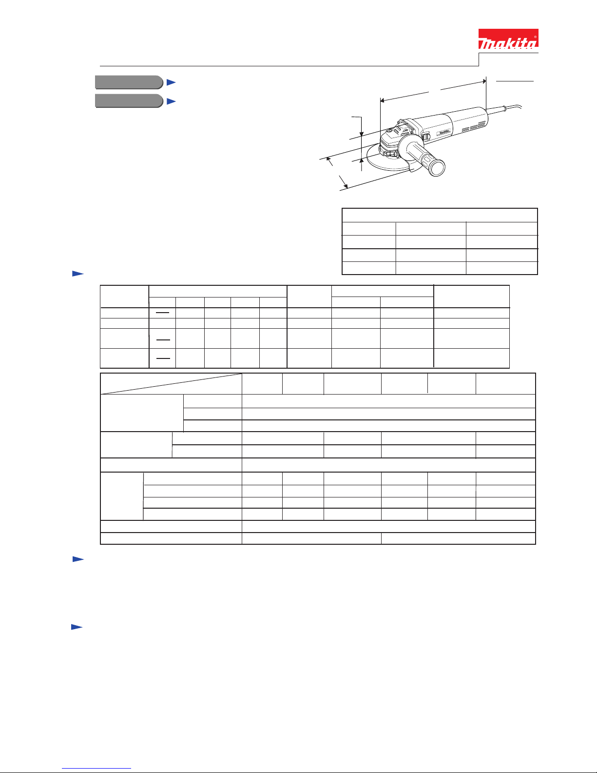
Electronic limiter for 9562C/CV, 9565C/CV Electronic controller for
9562C/CV, 9565C/CV
for keeping constant rpm.
even under loaded condition,
and for suppressing starting shock.
Tough Cord guard
excellent in flexibility
to protect power supply cord
from disconnection.
Speed control dial for
9562CV and 9565CV
for getting optimum rotating
speed to suit various work piece.
2
High sealed gear housing
to prevent leaking of grease
Adjustable wheel
cover's position
Wheel cover's position can be
adjusted without any tool.
High power and tough motor
9565C/CV: 1,400W
9562C/CV: 1,100W
9565 : 900W
9562 : 800W
High power from slim and compact body
thanks to new S60 type motor and electronic
control system.(only Model 9565C/CV and 9562C/CV)
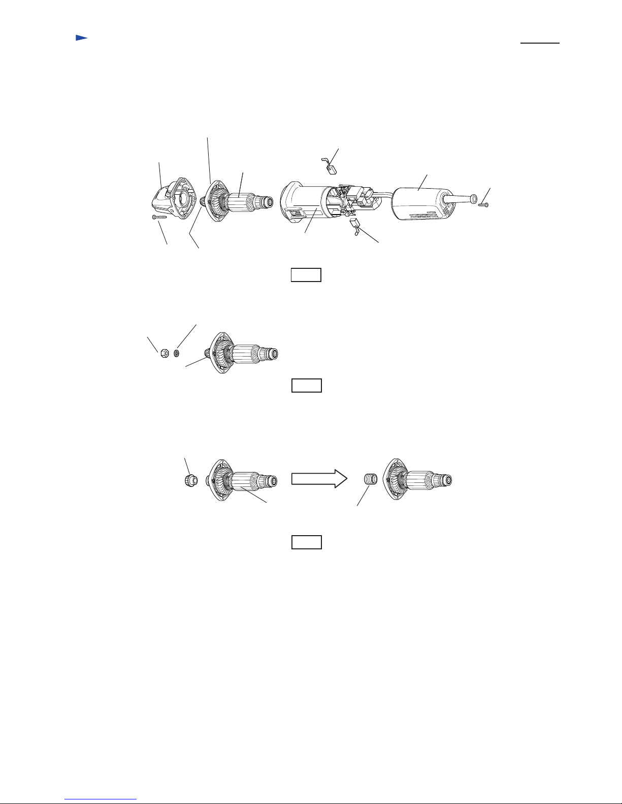
Jig zag, and powdered varnish coating on
armature and field ensure effective protection
from sharp grinding dust.
"Super Join System - SJS"
Lock spring joining spiral bevel gear
and armature shaft provides following
benefits.
* Smooth and comfortable grinding work.
* Suppression of shock by accidental
wheel lock during work.
* Prevention of damage on gear coming
from accidental wheel lock.
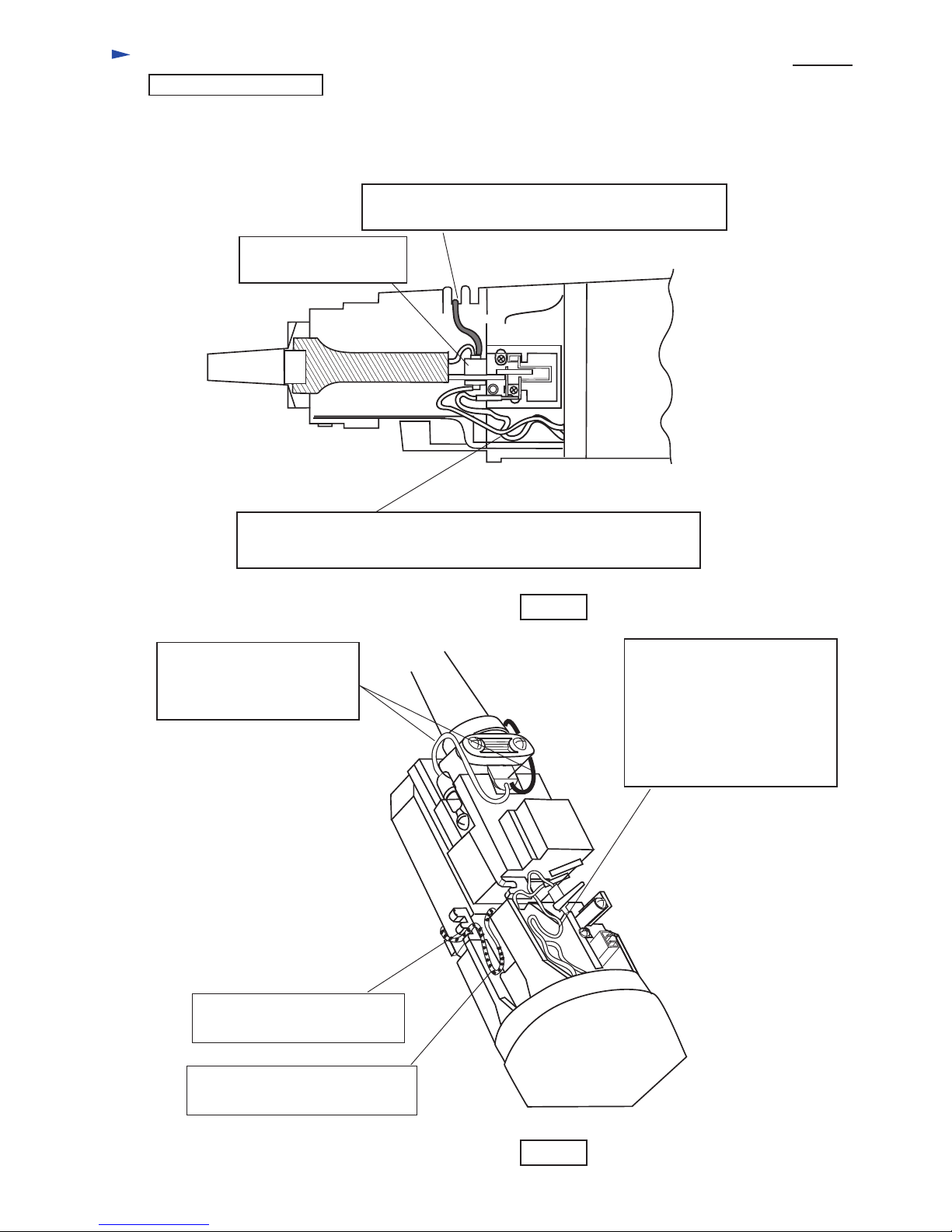
Protection from dust
Dust proof bearing Labyrinth structure Dust proof washer
Fan side of armature
Commutator side of armature
Wheel side of spindle X
X
**
**
: The spindle portion is protected from not only dust but also intruding water firmly.
Double Labyrinth

P 3 / 10
Comparison of products
Products without speed control
Manufacturer MAKITA
Model No.
Motor size
Auto break carbon brush
Soft start
Constant speed
Current limiter
Clutch
Power input (W)
Wheel diameter: mm (")
No load speed
: (min -1= rpm)
Electronic
features
Speed control dial
Net weight
: Kg (lbs)
9562 9565C A-2 A-49562C 9565
800 1,400 9001,100
11,000
*(10,500)
11,000
*(10,500)
11,000
900
A
125 (5)
11,000
S60-45 S60-55
No
No
No
No
No
No
No
No No No No
*Yes *Yes *Yes *Yes
Yes
Yes
Yes
Yes
No
Yes Yes Yes Yes
Yes
Yes No Yes
Yes No Yes
Yes No Yes
No
No
Yes
Yes
Yes
No
Yes
No
1.7
(3.7)
1.7
(3.7)
1.8
(4.0)
1.6
(3.5)
1.8
(4.0)
1.8
(4.0)
1.75
(3.9)
1,020 **(920) 1,400
58-42
58-56 58-56
*(10,500) : for North AmericA
**(920) : for North America
( Angle grinders 125mm )
125 (5) 125 (5) 125 (5)
A-3
Products without speed control
Manufacturer MAKITA
Model No.
Motor size
Auto break carbon brush
Soft start
Constant speed
Current limiter
Clutch
Power input (W)
Wheel diameter: mm (")
No load speed
: (min -1= rpm)
Electronic
features
Speed control dial
Net weight
: Kg (lbs)
9562 9565C B-2 C-29562C 9565
800 1,400 1,010 1,0101,100
11,000
*(10,500) 10,000
900
B
125 (5)
9,000
S60-45 S60-55
No
No
No
No
Yes
Yes
Yes
No No No No
*Yes *Yes *Yes *Yes
Yes
Yes
Yes
Yes
No
Yes Yes Yes No
Yes
Yes No No
Yes No No
Yes No No
No
No
Yes
Yes
Yes
No
No
No
Yes
Yes
Yes
No
No
No
1.7
(3.7)
1.7
(3.7)
1.8
(4.0)
1.9
(4.2)
1.9
(4.2)
1.8
(4.0)
1.6
(3.5)
2.1
(4.6)
1,000 1,400
62.5-45
55-55
125 (5) 125 (5)
C-1
C
10,000 10,000
C-3
62.5-58 62.5-58
Products with speed control
Manufacturer MAKITA
Model No.
Motor size
Auto break carbon brush
Soft start
Constant speed
Current limiter
Clutch
Power input (W)
Wheel diameter: mm (")
No load speed
: (min -1= rpm)
Electronic
features
Speed control dial
Net weight
: Kg (lbs)
9565CV9562CV
1,400 1,400
1,0201,100
2,800 - 11,000 2,800 - 11,000
*(2,800 - 10,500)
125 (5) 125 (5) 125 (5)
S60-45 S60-55
Yes
*Yes *Yes
Yes
Yes
Yes
Yes
Yes
Yes
Yes
Yes
Yes
Yes
Yes
Yes
Yes
Yes
Yes
Yes
Yes
Yes
Yes
1.7
(3.7) 1.6
(3.5)
1.8
(4.0)
1.8
(4.0)
1.9
(4.2)
( Angle grinders 125mm )
A
A-5 A-6
58-42 58-56
No No
Yes
Yes
Yes
Yes
D-1
D
1,400
7,000 - 10,500
Yes
Yes
*(10,500) : for North America
*(2,800 - 10,500) : for North America
*Yes : equiped with "Super joint system-SJS"

Repair P 4 / 10
Tapping screw 4x18
Rear cover
Motor housing
Carbon brush
Armature
assembly
Gear housing
cover
Gear housing
Tapping screw 4x28
<1> Replacing spiral bevel gear 11
Spiral bevel gear 11
(1) Remove tapping screw 4x18 and detach rear cover from motor housing.
And remove carbon brush as illustrated in Fig. 1.
(2) Remove tapping screw 4x28 and detach gear housing from motor housing.
And remove armature with gear housing cover as illustrated in Fig. 1.
Fig. 1
Fig. 2
Fig. 3
(3) Detach hex nut M6 and flat washer 6 from armature as illustrated in Fig.2.
(4) Remove spiral bevel gear 11 with bearing extractor No.1R269. And remove lock spring 12 by turning it
anti-clockwise. When removing, grip lock spring 12 with gloved hand for anti-skid.
Hex nut M6 Flat washer 6
Spiral bevel gear 11
Lock spring 12
Armature
assembly
< Note > Replace lock spring 12 together, when replacing spiral bevel gear 11.
(5) When assembling spiral bevel gear 11 to armature, take the reverse step.
Carbon brush

P 5 / 10
Attaching carbon brush
Connect the receptacle of carbon brush with the terminal of brush holder
by pushing in the direction of the arrow, as illustrated in Fig. 4.
Terminal of
brush holder
Receptacle of carbon brush Carbon brush
Brush holder
Push the receptacle of carbon brush until it stops as illustrated in Fig. 4A.
Incompletely attached receptacle
of carbon brush
Completely attached receptacle
of carbon brush
Repair
Fig. 4
Fig. 4A
Fig. 4B

Circuit diagram P 6 /10
Controller
Speed
Control
Dial
Field
Brush holder
( controller side )
Brush holder
( switch block side )
SB1
SB2
SB3
Switch block
Power supply
cord
SB4
White or blue
White
Black
P2
P1
Model 9562C,CV / Model 9565C,CV
< Note >
The numbers, SB1, SB2, SB3 and SB4 are indicated on the switch block.
with electronic features
Model 9562C and 9565C : without speed control dial
Model 9562CV and 9565CV : with speed control dial
Model 9562 / Model 9565
Field
Brush holder
( controller side )
Brush holder
( switch block side )
SB1
SB2
SB3
Switch block
Power supply
cord
SB4
White
White
Black
P2
P1
without electronic features
< Note >
The numbers, SB1, SB2, SB3 and SB4 are indicated on the switch block.
Black
Fig. 5
Fig. 6

Circuit diagram P 7 / 10
Field
Brush holder
( controller side )
Brush holder
( switch block side )
SB1
SB2
SB3
Switch block
Power supply
cord
SB4 White
White
Black
EMC. unit
White
Model 9562 / Model 9565
without electronic features
with EMC unit

Fix lead wires of controller
with lead holder.
Put their slack part in the place
as illustrated in Fig.8.
Do not loosen the lead
wires of filed in motor
housing.
Put the loosened ones in the
place as illustrated
in Fig.8.
Put lead wires of power
supply cord by strain relief
as illustrated in Fig. 8.
Model 9562C,CV / Model 9565C,CV
with electronic features
Wiring diagram P 8 / 10
Put the lead wires of controller in the lead holder
so that they are not slacken.
Be careful not to loosen the lead wires of field in motor housing.
Put the loosened lead wires in the above place.
Model 9562C,CV / Model 9565C,CV
with electronic features
Model 9562C and 9565C : without speed control dial
Model 9562CV and 9565CV : with speed control dial
Speed
Control
Dial
Fig. 7
Fig. 8

Wiring diagram P 9 / 10
Do not loosen the lead
wires of filed in motor
housing.
Put the loosened ones in the
place as illustrated
in Fig.10.
Put lead wires of power
supply cord by strain relief
as illustrated in Fig. 10.
Model 9562 / Model 9565
without electronic features
Model 9562 / Model 9565
without electronic features
Be careful not to loosen the lead wire of field in
motor housing.
Switch lever
Fig. 9
Fig. 10

Wiring diagram P 10 / 10
Fix lead wires of EMC unit
with lead holder.
Put their slack part in the place
as illustrated in Fig.12.
Do not loosen the lead
wires of filed in motor
housing.
Put the loosened ones in the
place as illustrated
in Fig.12.
Put lead wires of power
supply cord by strain relief
as illustrated in Fig. 14.
Model 9562 / Model 9565
without electronic features
with EMC unit
Fix the lead wires of EMC unit in the lead holder
so that they are not slacken.
Assemble the terminal
as illustrated below.
Be careful not to loosen the lead wires of field in motor housing.
Put the loosened lead wires in the above place.
Fig. 11
Fig. 12
This manual suits for next models
5
Table of contents
Other Makita Grinder manuals

Makita
Makita GD0600 Quick start guide

Makita
Makita GA039G User manual

Makita
Makita GA7050 User manual

Makita
Makita GA4540R User manual

Makita
Makita 9015B User manual

Makita
Makita DGA419 User manual

Makita
Makita M9504 User manual

Makita
Makita GA011G User manual

Makita
Makita 9047L User manual

Makita
Makita 9556HN Manual

Makita
Makita 9560Z User manual

Makita
Makita GA7020 User manual

Makita
Makita 9077 User manual

Makita
Makita DGA701 User manual

Makita
Makita GD0601 User manual

Makita
Makita GA5040 User manual

Makita
Makita GA5080 User manual

Makita
Makita GA5041C User manual

Makita
Makita GA4042C Manual

Makita
Makita GA4030 User manual