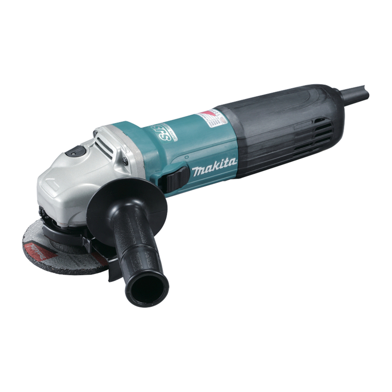
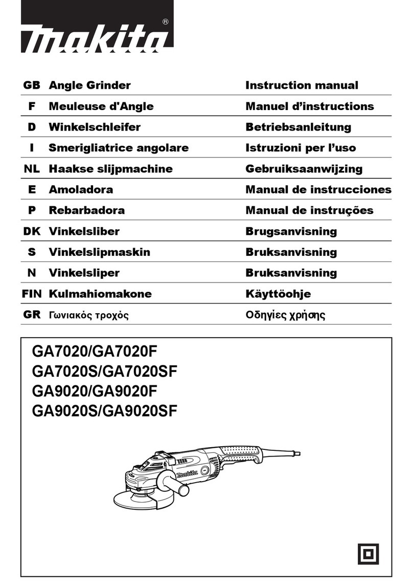
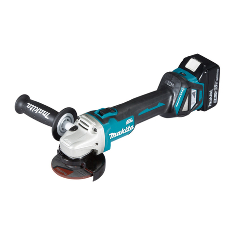
Makita DGA404 User manual

DGA404
DGA454
DGA504
EN Cordless Angle Grinder INSTRUCTION MANUAL 6
UK Бездротова кутова
шліфувальна машина
ІНСТРУКЦІЯ З
ЕКСПЛУАТАЦІЇ 15
PL Akumulatorowa szlierka
kątowa INSTRUKCJA OBSŁUGI 26
RO Polizor unghiular cu
acumulator MANUAL DE INSTRUCŢIUNI 37
DE Akku-Winkelschleifer BEDIENUNGSANLEITUNG 47
HU Akkumulátoros sarokcsiszoló HASZNÁLATI KÉZIKÖNYV 58
SK Ručná uhlová brúska NÁVOD NA OBSLUHU 68
CS Akumulátorová úhlová
bruska NÁVOD K OBSLUZE 78

1
2
3
1
1
2
1
1
1
1
2
3
4
Fig.1
Fig.2
Fig.3
Fig.4
Fig.5
Fig.6
Fig.7
Fig.8
2

1
2
3
1
23
1
2
3
1
2
1
2
4
3
1
12
Fig.9
Fig.10
Fig.11
Fig.12
Fig.13
Fig.14
Fig.15
Fig.16
3

1
2
3
4
1
2
3
AB
1
2
3
4
16 mm (5/8″) 16 mm (5/8″)
11
44
23
11
44
23
11
44
23
11
44
23
Fig.17
Fig.18
Fig.19
Fig.20
Fig.21
Fig.22
Fig.23
Fig.24
4

1
1
1
2
1
2
5
22
11
12
4
3
5
6
7
8
9
10
1
13
3
14
5
3
Fig.29
Fig.25
Fig.26
Fig.27
Fig.28
5

6ENGLISH
ENGLISH (Original instructions)
SPECIFICATIONS
Model DGA404 DGA454 DGA504
Wheel diameter 100 mm (4") 115 mm (4-1/2") 125 mm (5")
Max. wheel thickness 6.4 mm (1/4") 6.4 mm (1/4") 6.4 mm (1/4")
Spindle thread M10 M14 or 5/8" (country specic)
Rated speed (n) / No load speed (n0)8,500 min-1
Overall length With battery cartridge
BL1815N, BL1820, BL1820B
348 mm
With battery cartridge BL1830,
BL1830B, BL1840, BL1840B,
BL1850, BL1850B, BL1860B
362 mm
Net weight With battery cartridge
BL1815N, BL1820, BL1820B
2.2 kg 2.3 kg 2.3 kg
With battery cartridge BL1830,
BL1830B, BL1840, BL1840B,
BL1850, BL1850B, BL1860B
2.4 kg 2.5 kg 2.5 kg
Rated voltage D.C. 18 V
• Due to our continuing program of research and development, the specications herein are subject to change with-
out notice.
• Specications and battery cartridge may differ from country to country.
• Weight, with battery cartridge, according to EPTA-Procedure 01/2003
Intended use
The tool is intended for grinding, sanding and cutting of
metal and stone materials without the use of water.
Noise
The typical A-weighted noise level determined accord-
ing to EN60745:
Model DGA404
Sound pressure level (LpA) : 80 dB (A)
Sound power level (LWA) : 91 dB (A)
Uncertainty (K) : 3 dB (A)
Model DGA454, DGA504
Sound pressure level (LpA) : 79 dB (A)
Uncertainty (K) : 3 dB (A)
The noise level under working may exceed 80 dB (A).
Wear ear protection
Vibration
The vibration total value (tri-axial vector sum) deter-
mined according to EN60745:
Model DGA404
Work mode : surface grinding with normal side grip
Vibration emission (ah,AG) : 4.5 m/s2
Uncertainty (K) : 1.5 m/s2
Work mode : surface grinding with anti vibration side grip
Vibration emission (ah,AG) : 4.0 m/s2
Uncertainty (K) : 1.5 m/s2
Work mode: disc sanding
Vibration emission (ah,DS) : 2.5 m/s2or less
Uncertainty (K) : 1.5 m/s2
Model DGA454, DGA504
Work mode : surface grinding with normal side grip
Vibration emission (ah,AG) : 6.5 m/s2
Uncertainty (K) : 1.5 m/s2
Work mode : surface grinding with anti vibration side grip
Vibration emission (ah,AG) : 6.0 m/s2
Uncertainty (K) : 1.5 m/s2
Work mode: disc sanding
Vibration emission (ah,DS) : 2.5 m/s2or less
Uncertainty (K) : 1.5 m/s2
NOTE: The declared vibration emission value has
been measured in accordance with the standard test
method and may be used for comparing one tool with
another.
NOTE: The declared vibration emission value
may also be used in a preliminary assessment of
exposure.
NOTE: The declared vibration emission value is used
for main applications of the power tool. However if the
power tool is used for other applications, the vibration
emission value may be different.
WARNING: The vibration emission during actual
use of the power tool can differ from the declared
emission value depending on the ways in which the
tool is used.
WARNING: Be sure to identify safety measures
to protect the operator that are based on an estima-
tion of exposure in the actual conditions of use (taking
account of all parts of the operating cycle such as
the times when the tool is switched off and when it is
running idle in addition to the trigger time).

7ENGLISH
For European countries only
EC Declaration of Conformity
Makita declares that the following Machine(s):
Designation of Machine:
Cordless Angle Grinder
Model No./ Type: DGA404,DGA454,DGA504
Conforms to the following European Directives:
2006/42/EC
They are manufactured in accordance with the following
standard or standardized documents:
EN60745
The technical le in accordance with 2006/42/EC is
available from:
Makita, Jan-Baptist Vinkstraat 2, 3070, Belgium
13.3.2014
Yasushi Fukaya
Director
Makita, Jan-Baptist Vinkstraat 2, 3070, Belgium
General Power Tool Safety Warnings
WARNING Read all safety warnings and all instruc-
tions. Failure to follow the warnings and instructions may
result in electric shock, re and/or serious injury.
Save all warnings and instructions for
future reference.
CORDLESS GRINDER SAFETY
WARNINGS
Safety Warnings Common for Grinding, Sanding,
Wire Brushing, or Abrasive Cutting-Off Operations:
1. This power tool is intended to function as a
grinder, sander, wire brush or cut-off tool.
Read all safety warnings, instructions, illus-
trations and specications provided with this
power tool. Failure to follow all instructions listed
below may result in electric shock, re and/or
serious injury.
2. Operations such as polishing are not rec-
ommended to be performed with this power
tool. Operations for which the power tool was not
designed may create a hazard and cause per-
sonal injury.
3. Do not use accessories which are not speci-
cally designed and recommended by the tool
manufacturer. Just because the accessory can
be attached to your power tool, it does not assure
safe operation.
4. The rated speed of the accessory must be at
least equal to the maximum speed marked on
the power tool. Accessories running faster than
their rated speed can break and y apart.
5. The outside diameter and the thickness of your
accessory must be within the capacity rating
of your power tool. Incorrectly sized accessories
cannot be adequately guarded or controlled.
6.
Threaded mounting of accessories must match
the grinder spindle thread. For accessories
mounted by anges, the arbour hole of the
accessory must t the locating diameter of the
ange. Accessories that do not match the mounting
hardware of the power tool will run out of balance,
vibrate excessively and may cause loss of control.
7.
Do not use a damaged accessory. Before each
use inspect the accessory such as abrasive
wheels for chips and cracks, backing pad for
cracks, tear or excess wear, wire brush for loose
or cracked wires. If power tool or accessory
is dropped, inspect for damage or install an
undamaged accessory. After inspecting and
installing an accessory, position yourself and
bystanders away from the plane of the rotating
accessory and run the power tool at maximum
no-load speed for one minute. Damaged acces-
sories will normally break apart during this test time.
8.
Wear personal protective equipment.
Depending on application, use face shield,
safety goggles or safety glasses. As appropri-
ate, wear dust mask, hearing protectors, gloves
and workshop apron capable of stopping small
abrasive or workpiece fragments. The eye pro-
tection must be capable of stopping ying debris
generated by various operations . The dust mask
or respirator must be capable of ltrating particles
generated by your operation. Prolonged exposure
to high intensity noise may cause hearing loss.
9. Keep bystanders a safe distance away from
work area. Anyone entering the work area
must wear personal protective equipment.
Fragments of workpiece or of a broken accessory
may y away and cause injury beyond immediate
area of operation.
10. Hold the power tool by insulated gripping
surfaces only, when performing an operation
where the cutting tool may contact hidden
wiring. Contact with a "live" wire will also make
exposed metal parts of the power tool "live" and
could give the operator an electric shock.
11. Never lay the power tool down until the acces-
sory has come to a complete stop. The spinning
accessory may grab the surface and pull the
power tool out of your control.
12. Do not run the power tool while carrying it at
your side. Accidental contact with the spinning
accessory could snag your clothing, pulling the
accessory into your body.
13. Regularly clean the power tool’s air vents. The
motor’s fan will draw the dust inside the housing
and excessive accumulation of powdered metal
may cause electrical hazards.
14. Do not operate the power tool near ammable
materials. Sparks could ignite these materials.
15. Do not use accessories that require liquid
coolants. Using water or other liquid coolants
may result in electrocution or shock.
Kickback and Related Warnings
Kickback is a sudden reaction to a pinched or snagged
rotating wheel, backing pad, brush or any other acces-
sory. Pinching or snagging causes rapid stalling of the
rotating accessory which in turn causes the uncon-
trolled power tool to be forced in the direction opposite
of the accessory’s rotation at the point of the binding.

8ENGLISH
For example, if an abrasive wheel is snagged or
pinched by the workpiece, the edge of the wheel that is
entering into the pinch point can dig into the surface of
the material causing the wheel to climb out or kick out.
The wheel may either jump toward or away from the
operator, depending on direction of the wheel’s move-
ment at the point of pinching. Abrasive wheels may also
break under these conditions.
Kickback is the result of power tool misuse and/or
incorrect operating procedures or conditions and can be
avoided by taking proper precautions as given below.
a) Maintain a rm grip on the power tool and
position your body and arm to allow you to
resist kickback forces. Always use auxiliary
handle, if provided, for maximum control over
kickback or torque reaction during start-up.
The operator can control torque reactions or kick-
back forces, if proper precautions are taken.
b) Never place your hand near the rotating acces-
sory. Accessory may kickback over your hand.
c) Do not position your body in the area where
power tool will move if kickback occurs.
Kickback will propel the tool in direction opposite
to the wheel’s movement at the point of snagging.
d) Use special care when working corners,
sharp edges etc. Avoid bouncing and snagging
the accessory. Corners, sharp edges or bouncing
have a tendency to snag the rotating accessory
and cause loss of control or kickback.
e) Do not attach a saw chain woodcarving
blade or toothed saw blade. Such blades create
frequent kickback and loss of control.
Safety Warnings Specic for Grinding and Abrasive
Cutting-Off Operations:
a) Use only wheel types that are recommended
for your power tool and the specic guard
designed for the selected wheel. Wheels for
which the power tool was not designed cannot be
adequately guarded and are unsafe.
b) The grinding surface of centre depressed
wheels must be mounted below the plane of
the guard lip. An improperly mounted wheel that
projects through the plane of the guard lip cannot
be adequately protected.
c) The guard must be securely attached to the
power tool and positioned for maximum safety,
so the least amount of wheel is exposed
towards the operator. The guard helps to protect
the operator from broken wheel fragments, acci-
dental contact with wheel and sparks that could
ignite clothing.
d) Wheels must be used only for recommended
applications. For example: do not grind with
the side of cut-off wheel. Abrasive cut-off wheels
are intended for peripheral grinding, side forces
applied to these wheels may cause them to
shatter.
e) Always use undamaged wheel anges that
are of correct size and shape for your selected
wheel. Proper wheel anges support the wheel
thus reducing the possibility of wheel breakage.
Flanges for cut-off wheels may be different from
grinding wheel anges.
f) Do not use worn down wheels from larger
power tools. Wheel intended for larger power tool
is not suitable for the higher speed of a smaller
tool and may burst.
Additional Safety Warnings Specic for Abrasive
Cutting-Off Operations:
a) Do not “jam” the cut-off wheel or apply
excessive pressure. Do not attempt to make an
excessive depth of cut. Overstressing the wheel
increases the loading and susceptibility to twisting
or binding of the wheel in the cut and the possibil-
ity of kickback or wheel breakage.
b) Do not position your body in line with and
behind the rotating wheel. When the wheel, at
the point of operation, is moving away from your
body, the possible kickback may propel the spin-
ning wheel and the power tool directly at you.
c) When wheel is binding or when interrupting
a cut for any reason, switch off the power
tool and hold the power tool motionless until
the wheel comes to a complete stop. Never
attempt to remove the cut-off wheel from the
cut while the wheel is in motion otherwise
kickback may occur. Investigate and take correc-
tive action to eliminate the cause of wheel binding.
d) Do not restart the cutting operation in the work-
piece. Let the wheel reach full speed and carefully
re-enter the cut. The wheel may bind, walk up or kick-
back if the power tool is restarted in the workpiece.
e) Support panels or any oversized workpiece
to minimize the risk of wheel pinching and
kickback. Large workpieces tend to sag under
their own weight. Supports must be placed under
the workpiece near the line of cut and near the
edge of the workpiece on both sides of the wheel.
f) Use extra caution when making a “pocket
cut” into existing walls or other blind areas. The
protruding wheel may cut gas or water pipes, elec-
trical wiring or objects that can cause kickback.
Safety Warnings Specic for Sanding Operations:
a) Do not use excessively oversized sanding
disc paper. Follow manufacturers recommen-
dations, when selecting sanding paper. Larger
sanding paper extending beyond the sanding
pad presents a laceration hazard and may cause
snagging, tearing of the disc or kickback.
Safety Warnings Specic for Wire Brushing
Operations:
a) Be aware that wire bristles are thrown by
the brush even during ordinary operation. Do
not overstress the wires by applying excessive
load to the brush. The wire bristles can easily
penetrate light clothing and/or skin.
b) If the use of a guard is recommended for
wire brushing, do not allow interference of the
wire wheel or brush with the guard. Wire wheel
or brush may expand in diameter due to work load
and centrifugal forces.
Additional Safety Warnings:
16.
When using depressed centre grinding wheels,
be sure to use only berglass-reinforced wheels.
17. NEVER USE Stone Cup type wheels with this
grinder. This grinder is not designed for these
types of wheels and the use of such a product
may result in serious personal injury.
18. Be careful not to damage the spindle, the
ange (especially the installing surface) or the
lock nut. Damage to these parts could result in
wheel breakage.
19. Make sure the wheel is not contacting the
workpiece before the switch is turned on.

9ENGLISH
20. Before using the tool on an actual workpiece,
let it run for a while. Watch for vibration or
wobbling that could indicate poor installation
or a poorly balanced wheel.
21. Use the specied surface of the wheel to per-
form the grinding.
22. Do not leave the tool running. Operate the tool
only when hand-held.
23. Do not touch the workpiece immediately after
operation; it may be extremely hot and could
burn your skin.
24. Observe the instructions of the manufacturer
for correct mounting and use of wheels.
Handle and store wheels with care.
25. Do not use separate reducing bushings or
adaptors to adapt large hole abrasive wheels.
26. Use only anges specied for this tool.
27. For tools intended to be tted with threaded
hole wheel, ensure that the thread in the wheel
is long enough to accept the spindle length.
28.
Check that the workpiece is properly supported.
29. Pay attention that the wheel continues to
rotate after the tool is switched off.
30.
If working place is extremely hot and humid, or
badly polluted by conductive dust, use a short-cir-
cuit breaker (30 mA) to assure operator safety.
31. Do not use the tool on any materials contain-
ing asbestos.
32. When use cut-off wheel, always work with
the dust collecting wheel guard required by
domestic regulation.
33. Cutting discs must not be subjected to any
lateral pressure.
34. Do not use cloth work gloves during operation.
Fibers from cloth gloves may enter the tool, which
causes tool breakage.
SAVE THESE INSTRUCTIONS.
WARNING: DO NOT let comfort or famil-
iarity with product (gained from repeated
use) replace strict adherence to safety
rules for the subject product. MISUSE or
failure to follow the safety rules stated in
this instruction manual may cause serious
personal injury.
Important safety instructions for
battery cartridge
1. Before using battery cartridge, read all instruc-
tions and cautionary markings on (1) battery
charger, (2) battery, and (3) product using
battery.
2. Do not disassemble battery cartridge.
3. If operating time has become excessively
shorter, stop operating immediately. It may
result in a risk of overheating, possible burns
and even an explosion.
4. If electrolyte gets into your eyes, rinse them
out with clear water and seek medical atten-
tion right away. It may result in loss of your
eyesight.
5. Do not short the battery cartridge:
(1) Do not touch the terminals with any con-
ductive material.
(2) Avoid storing battery cartridge in a con-
tainer with other metal objects such as
nails, coins, etc.
(3) Do not expose battery cartridge to water
or rain.
A battery short can cause a large current
ow, overheating, possible burns and even a
breakdown.
6. Do not store the tool and battery cartridge in
locations where the temperature may reach or
exceed 50 °C (122 °F).
7. Do not incinerate the battery cartridge even if
it is severely damaged or is completely worn
out. The battery cartridge can explode in a re.
8. Be careful not to drop or strike battery.
9. Do not use a damaged battery.
10. The contained lithium-ion batteries are subject
to the Dangerous Goods Legislation require-
ments.
For commercial transports e.g. by third parties,
forwarding agents, special requirement on pack-
aging and labeling must be observed.
For preparation of the item being shipped, consult-
ing an expert for hazardous material is required.
Please also observe possibly more detailed
national regulations.
Tape or mask off open contacts and pack up the
battery in such a manner that it cannot move
around in the packaging.
11. Follow your local regulations relating to dis-
posal of battery.
12. Use the batteries only with the products
specied by Makita. Installing the batteries to
non-compliant products may result in a re, exces-
sive heat, explosion, or leak of electrolyte.
SAVE THESE INSTRUCTIONS.
CAUTION: Only use genuine Makita batteries.
Use of non-genuine Makita batteries, or batteries that
have been altered, may result in the battery bursting
causing res, personal injury and damage. It will
also void the Makita warranty for the Makita tool and
charger.
Tips for maintaining maximum
battery life
1. Charge the battery cartridge before completely
discharged. Always stop tool operation and
charge the battery cartridge when you notice
less tool power.
2. Never recharge a fully charged battery car-
tridge. Overcharging shortens the battery
service life.
3. Charge the battery cartridge with room tem-
perature at 10 °C - 40 °C (50 °F - 104 °F). Let
a hot battery cartridge cool down before
charging it.
4. Charge the battery cartridge if you do not use
it for a long period (more than six months).

10 ENGLISH
FUNCTIONAL
DESCRIPTION
CAUTION:
• Always be sure that the tool is switched off and
the battery cartridge is removed before adjust-
ing or checking function on the tool.
Installing or removing battery
cartridge
► Fig.1: 1. Button 2. Red indicator 3. Battery cartridge
CAUTION:
• Always switch off the tool before installing or
removing of the battery cartridge.
• Hold the tool and the battery cartridge rmly
when installing or removing battery car-
tridge. Failure to hold the tool and the battery
cartridge rmly may cause them to slip off your
hands and result in damage to the tool and
battery cartridge and a personal injury.
To remove the battery cartridge, slide it from the tool
while sliding the button on the front of the cartridge.
To install the battery cartridge, align the tongue on the
battery cartridge with the groove in the housing and slip
it into place. Insert it all the way until it locks in place
with a little click. If you can see the red indicator on the
upper side of the button, it is not locked completely.
CAUTION:
• Always install the battery cartridge fully until the
red indicator cannot be seen. If not, it may acci-
dentally fall out of the tool, causing injury to you
or someone around you.
• Do not install the battery cartridge forcibly. If the
cartridge does not slide in easily, it is not being
inserted correctly.
Switch action
CAUTION:
• Before installing the battery cartridge into the
tool, always check to see that the slide switch
actuates properly and returns to the "OFF"
position when the rear of the slide switch is
depressed.
• Switch can be locked in "ON" position for ease
of operator comfort during extended use. Apply
caution when locking tool in "ON" position and
maintain rm grasp on tool.
► Fig.2: 1. Slide switch
To start the tool, slide the slide switch toward the "I
(ON)" position by pushing the rear of the slide switch.
For continuous operation, press the front of the slide
switch to lock it.
To stop the tool, press the rear of the slide switch, then
slide it toward the "O (OFF)" position.
Accidental re-start preventive
function
Even if the battery cartridge is installed on the tool with
the slide switch in the "I (ON)" position, the tool does
not start.
To start the tool, rst slide the slide switch toward the
"O (OFF)" position and then slide it toward the "I (ON)"
position.
Electronic torque control function
The tool electronically detects situations where the
wheel or accessory may be at risk to be bound. In the
situation, the tool is automatically shut off to prevent
further rotation of the spindle (it does not prevent
kickback).
To restart the tool, switch off the tool rst, remove the
cause of sudden drop in the rotation speed, and then
turn the tool on.
Indicating the remaining battery
capacity
Only for battery cartridges with the indicator
► Fig.3: 1. Indicator lamps 2. Check button
Press the check button on the battery cartridge to indi-
cate the remaining battery capacity. The indicator lamps
light up for a few seconds.
Indicator lamps Remaining
capacity
Lighted Off Blinking
75% to 100%
50% to 75%
25% to 50%
0% to 25%
Charge the
battery.
The battery
may have
malfunctioned.
NOTE: Depending on the conditions of use and the
ambient temperature, the indication may differ slightly
from the actual capacity.
Indicating remaining battery
capacity
(Country specic)
► Fig.4: 1. Battery indicator
When you turn the tool on, the battery indicator shows
the remaining battery capacity.
The remaining battery capacity is shown as the follow-
ing table.

11 ENGLISH
Battery indicator status
Remaining battery capacity
50% - 100%
20% - 50%
0% - 20%
Charge the battery
On Off Blinking
Automatic speed change function
► Fig.5: 1. Mode indicator
Mode indicator status Operation mode
High speed mode
High torque mode
This tool has "high speed mode" and "high torque
mode". It automatically changes operation mode
depending on the work load. When mode indicator
lights up during operation, the tool is in high torque
mode.
Tool / battery protection system
The tool is equipped with a tool/battery protection sys-
tem. This system automatically cuts off power to the
motor to extend tool and battery life.
The tool will automatically stop during operation if the
tool or battery is placed under one of the following con-
ditions. In some conditions, the indicator lights up.
Overload protection
When the tool is operated in a manner that causes it to
draw an abnormally high current, the tool automatically
stops without any indications. In this situation, turn the
tool off and stop the application that caused the tool to
become overloaded. Then turn the tool on to restart.
Overheat protection for tool
When the tool is overheated, the tool stops automati-
cally and the battery indicator shows following state. In
this situation, let the tool cool before turning the tool on
again.
Battery indicator
Tool is overheated
On Off Blinking
Releasing protection lock
When the protection system works repeatedly, the tool
is locked and the battery indicator shows the following
state.
Protection lock works
Battery indicator On OffBlinking
In this situation, the tool does not start even if turning
the tool off and on. To release the protection lock,
remove the battery, set it to the battery charger and wait
until the charging nishes.
Shaft lock
CAUTION:
• Never actuate the shaft lock when the spindle is
moving. The tool may be damaged.
► Fig.6: 1. Shaft lock
Press the shaft lock to prevent spindle rotation when
installing or removing accessories.
ASSEMBLY
CAUTION:
• Always be sure that the tool is switched off and
the battery cartridge is removed before carrying
out any work on the tool.
Installing side grip (handle)
CAUTION:
• Always be sure that the side grip is installed
securely before operation.
► Fig.7
Screw the side grip securely on the position of the tool
as shown in the gure.
Installing or removing wheel guard
(For depressed center wheel,
multi disc / abrasive cut-off wheel,
diamond wheel)
WARNING:
• When using a depressed center grinding wheel/
Multi-disc, ex wheel, wire wheel brush, cut-off
wheel or diamond wheel, the wheel guard must
be tted on the tool so that the closed side of the
guard always points toward the operator.
• When using an abrasive cut-off / diamond
wheel, be sure to use only the special wheel
guard designed for use with cut-off wheels. (In
some European countries, when using a dia-
mond wheel, the ordinary guard can be used.
Follow the regulations in your country.)

12 ENGLISH
For tool with clamp lever type wheel guard
► Fig.8: 1. Wheel guard 2. Bearing box 3. Screw
4. Lever
Loosen the lever on the wheel guard after loosening the
screw. Mount the wheel guard with the protrusion on the
wheel guard band aligned with the notch on the bearing
box. Then rotate the wheel guard to such an angle that
it can protect the operator according to work.
► Fig.9: 1. Screw 2. Lever 3. Wheel guard
Tighten the lever to fasten the wheel guard. If the lever
is too tight or too loose to fasten the wheel guard,
loosen or tighten the screw to adjust the tightening of
the wheel guard band.
To remove wheel guard, follow the installation proce-
dure in reverse.
For tool with locking screw type
wheel guard
► Fig.10: 1. Wheel guard 2. Bearing box 3. Screw
Mount the wheel guard with the protrusions on the
wheel guard band aligned with the notches on the bear-
ing box. Then rotate the wheel guard around 180° coun-
terclockwise. Be sure to tighten the screw securely.
To remove wheel guard, follow the installation proce-
dure in reverse.
Installing or removing depressed center
wheel or ap disc (optional accessory)
WARNING:
• When using a depressed center wheel or ap
disc, the wheel guard must be tted on the tool
so that the closed side of the guard always
points toward the operator.
• Only actuate the shaft lock when the spindle is
not moving.
► Fig.11: 1. Lock nut 2. Depressed center wheel
3. Inner ange
Mount the inner ange onto the spindle. Fit the wheel/disc
on the inner ange and screw the lock nut onto the spindle.
► Fig.12: 1. Lock nut wrench 2. Shaft lock
To tighten the lock nut, press the shaft lock rmly so
that the spindle cannot revolve, then use the lock nut
wrench and securely tighten clockwise.
To remove the wheel, follow the installation procedure
in reverse.
Installing or removing Ezynut
(optional accessory)
CAUTION:
• Do not use Ezynut with Super Flange or angle
grinder with “F” on the end of the model No.
Those anges are so thick that the entire thread
cannot be retained by the spindle.
► Fig.13: 1. Ezynut 2. Abrasive wheel 3. Inner ange
4. Spindle
Mount inner ange, abrasive wheel and Ezynut onto the
spindle so that Makita Logo on Ezynut faces outside.
► Fig.14: 1. Shaft lock
Press shaft lock rmly and tighten Ezynut by turning the
abrasive wheel clockwise as far as it turns.
Turn the outside ring of Ezynut counterclockwise to loosen.
► Fig.15: 1. Arrow 2. Notch
► Fig.16
NOTE:
• Ezynut can be loosened by hand as long as
the arrow points the notch. Otherwise a lock
nut wrench is required to loosen it. Insert one
pin of the wrench into a hole and turn Ezynut
counterclockwise.
Installing or removing ex wheel
Optional accessory
WARNING: Always use supplied guard when
ex wheel is on tool. Wheel can shatter during use
and guard helps to reduce chances of personal injury.
► Fig.17: 1. Lock nut 2. Flex wheel 3. Back up pad
4. Inner ange
Follow instructions for depressed center wheel but also
use back up pad over wheel. See order of assembly on
accessories page in this manual.
Installing or removing abrasive disc
(optional accessory)
► Fig.18: 1. Sanding lock nut 2. Abrasive disc
3. Rubber pad
Mount the rubber pad onto the spindle. Fit the disc on
the rubber pad and screw the lock nut onto the spindle.
To tighten the lock nut, press the shaft lock rmly so
that the spindle cannot revolve, then use the lock nut
wrench and securely tighten clockwise.
To remove the disc, follow the installation procedure in
reverse.
NOTE:
• Use sander accessories specied in this man-
ual. These must be purchased separately.
OPERATION
WARNING:
• It should never be necessary to force the tool.
The weight of the tool applies adequate pres-
sure. Forcing and excessive pressure could
cause dangerous wheel breakage.
• ALWAYS replace wheel if tool is dropped while
grinding.
• NEVER bang or hit grinding disc or wheel onto
work.
• Avoid bouncing and snagging the wheel, espe-
cially when working corners, sharp edges etc.
This can cause loss of control and kickback.
• NEVER use tool with wood cutting blades and
other sawblades. Such blades when used on a
grinder frequently kick and cause loss of control
leading to personal injury.

13 ENGLISH
CAUTION:
• Never switch on the tool when it is in contact
with the workpiece, it may cause an injury to
operator.
• Always wear safety goggles or a face shield
during operation.
• After operation, always switch off the tool and
wait until the wheel has come to a complete stop
before putting the tool down.
Grinding and sanding operation
► Fig.19
ALWAYS hold the tool rmly with one hand on housing
and the other on the side handle. Turn the tool on and
then apply the wheel or disc to the workpiece.
In general, keep the edge of the wheel or disc at an
angle of about 15 degrees to the workpiece surface.
During the break-in period with a new wheel, do not work
the grinder in the B direction or it will cut into the workpiece.
Once the edge of the wheel has been rounded off by use,
the wheel may be worked in both A and B direction.
Operation with abrasive cut-off /
diamond wheel
Optional accessory
WARNING: When using an abrasive cut-off
/ diamond wheel, be sure to use only the special
wheel guard designed for use with cut-off wheels.
(In some European countries, when using a diamond
wheel, the ordinary guard can be used. Follow the
regulations in your country.)
WARNING:
NEVER use cut-off wheel for side grinding.
WARNING:
Do not "jam" the wheel or apply
excessive pressure. Do not attempt to make an exces-
sive depth of cut. Overstressing the wheel increases
the loading and susceptibility to twisting or binding of the
wheel in the cut and the possibility of kickback, wheel
breakage and overheating of the motor may occur.
WARNING: Do not start the cutting operation
in the workpiece. Let the wheel reach full speed
and carefully enter into the cut moving the tool
forward over the workpiece surface. The wheel
may bind, walk up or kickback if the power tool is
started in the workpiece.
WARNING:
During cutting operations, never
change the angle of the wheel. Placing side pressure
on the cut-off wheel (as in grinding) will cause the wheel
to crack and break, causing serious personal injury.
WARNING: A diamond wheel shall be oper-
ated perpendicular to the material being cut.
► Fig.20: 1. Lock nut 2. Abrasive cut-off wheel / dia-
mond wheel 3. Inner ange 4. Wheel guard
for abrasive cut-off wheel / diamond wheel
As for the installation, follow the instructions for
depressed center wheel.
The direction for mounting the lock nut and the
inner ange varies by wheel type and thickness.
Refer to the following gures.
For 100 mm (4″) model
When installing the abrasive cut-off wheel:
► Fig.21:
1. Lock nut 2. Abrasive cut-off wheel (Thinner
than 4 mm (5/32")) 3. Abrasive cut-off wheel
(4 mm (5/32") or thicker) 4. Inner ange
When installing the diamond wheel:
► Fig.22: 1. Lock nut 2. Diamond wheel (Thinner than
4 mm (5/32″)) 3. Diamond wheel (4 mm
(5/32″) or thicker) 4. Inner ange
For 115 mm (4 - 1/2″) / 125 mm (5″) model
When installing the abrasive cut-off wheel:
► Fig.23:
1. Lock nut 2. Abrasive cut-off wheel (Thinner
than 4 mm (5/32")) 3. Abrasive cut-off wheel
(4 mm (5/32") or thicker) 4. Inner ange
When installing the diamond wheel:
► Fig.24: 1. Lock nut 2. Diamond wheel (Thinner than
4 mm (5/32″)) 3. Diamond wheel (4 mm
(5/32″) or thicker) 4. Inner ange
Operation with wire cup brush
(optional accessory)
CAUTION:
•
Check operation of brush by running tool with no load,
insuring that no one is in front of or in line with brush.
•
Do not use brush that is damaged, or which is out of
balance. Use of damaged brush could increase poten-
tial for injury from contact with broken brush wires.
► Fig.25: 1. Wire cup brush
Remove the battery cartridge from the tool and place it
upside down allowing easy access to spindle. Remove
any accessories on spindle. Thread wire cup brush onto
spindle and tighten with supplied wrench. When using
brush, avoid applying too much pressure which causes
over bending of wires, leading to premature breakage.
Operation with wire wheel brush
(optional accessory)
CAUTION:
• Check operation of wire wheel brush by running
tool with no load, insuring that no one is in front
of or in line with the wire wheel brush.
•
Do not use wire wheel brush that is damaged, or which is
out of balance. Use of damaged wire wheel brush could
increase potential for injury from contact with broken wires.
• ALWAYS use guard with wire wheel brushes,
assuring diameter of wheel ts inside guard.
Wheel can shatter during use and guard helps
to reduce chances of personal injury.
► Fig.26: 1. Wire wheel brush
Remove the battery cartridge from the tool and place it
upside down allowing easy access to spindle. Remove
any accessories on spindle. Thread wire wheel brush
onto spindle and tighten with the wrenches.
When using wire wheel brush, avoid applying too much
pressure which causes over bending of wires, leading
to premature breakage.

14 ENGLISH
MAINTENANCE
CAUTION:
• Always be sure that the tool is switched off and
the battery cartridge is removed before attempt-
ing to perform inspection or maintenance.
• Never use gasoline, benzine, thinner, alcohol
or the like. Discoloration, deformation or cracks
may result.
► Fig.27: 1. Exhaust vent 2. Inhalation vent
The tool and its air vents have to be kept clean.
Regularly clean the tool's air vents or whenever the
vents start to become obstructed.
► Fig.28: 1. Dust cover
Remove the dust cover from inhalation vent and clean it
for smooth air circulation.
NOTE:
• Clean out the dust cover when it is clogged with
dust or foreign matters. Continuing operation
with a clogged dust cover may damage the tool.
To maintain product SAFETY and RELIABILITY, repairs,
any other maintenance or adjustment should be per-
formed by Makita Authorized Service Centers, always
using Makita replacement parts.
OPTIONAL
ACCESSORIES
CAUTION:
• These accessories or attachments are recom-
mended for use with your Makita tool specied
in this manual. The use of any other accessories
or attachments might present a risk of injury to
persons. Only use accessory or attachment for
its stated purpose.
If you need any assistance for more details regard-
ing these accessories, ask your local Makita Service
Center.
• Makita genuine battery and charger
► Fig.29
-100 mm (4″) model 115 mm (4-1/2″) model 125 mm (5″) model
1Grip 36
2Wheel Guard (for grinding wheel)
3Inner ange Inner ange / Super ange *1*2 Inner ange / Super ange
4Depressed center wheel / Flap disc
5Lock nut Lock nut / Ezynut *1*2 Lock nut / Ezynut *2
6Back up pad
7Flex wheel
8Rubber pad 76 Rubber pad 100 Rubber pad 115
9Abrasive disc
10 Sanding lock nut
11 Wire wheel brush
12 Wire cup brush
13 Wheel Guard (for cut-off wheel) *3
14 Abrasive cut-off wheel / Diamond wheel
-Lock nut wrench
NOTE: *1 Only for tools with M14 spindle thread.
NOTE: *2 Do not use Super ange and Ezynut together.
NOTE: *3 In some European countries, when using a diamond wheel, the ordinary guard can be used instead of the
special guard covering the both side of the wheel. Follow the regulations in your country.
NOTE:
• Some items in the list may be included in the
tool package as standard accessories. They
may differ from country to country.

15 УКРАЇНСЬКА
УКРАЇНСЬКА (Оригінальні вказівки)
ТЕХНІЧНІ ХАРАКТЕРИСТИКИ
Модель DGA404 DGA454 DGA504
Діаметр диска 100 мм (4") 115 мм (4-1/2") 125 мм (5")
Макс. товщина диска 6,4 мм (1/4") 6,4 мм (1/4") 6,4 мм (1/4")
Різьба шпинделя M10 M14 або 5/8" (залежно від країни)
Номінальна швидкість (n) / швидкість без навантаження (n0)8500 хв-1
Загальна довжина Із касетою з акумулятором
BL1815N, BL1820, BL1820B
348 мм
Із касетою з акумулятором
BL1830, BL1830B, BL1840,
BL1840B, BL1850, BL1850B,
BL1860B
362 мм
Чиста вага Із касетою з акумулятором
BL1815N, BL1820, BL1820B
2,2 кг 2,3 кг 2,3 кг
Із касетою з акумулятором
BL1830, BL1830B, BL1840,
BL1840B, BL1850, BL1850B,
BL1860B
2,4 кг 2,5 кг 2,5 кг
Номінальна напруга 18 В пост. струму
• Через те, що ми не припиняємо програми досліджень і розвитку, наведені тут технічні характеристики
можуть бути змінені без попередження.
• Технічні характеристики приладу та касета з акумулятором можуть відрізнятися в різних країнах.
• Вага разом з касетою з акумулятором відповідно до EPTA-Procedure 01/2003
Призначення
Інструмент призначений для шліфування, зачистки
та різання металевих та мінеральних матеріалів без
використання води.
Шум
Рівень шуму за шкалою А у типовому виконанні,
визначений відповідно до EN60745:
Модель DGA404
Рівень звукового тиску (LpA): 80 дБ (A)
Рівень звукової потужності (LWA): 91 дБ (A)
Похибка (K): 3 дБ (A)
Модель DGA454, DGA504
Рівень звукового тиску (LpA): 79 дБ (A)
Похибка (K): 3 дБ (A)
Рівень шуму під час роботи може перевищувати 80 дБ (A).
Користуйтеся засобами захисту слуху
Вібрація
Загальна величина вібрації (сума трьох векторів)
визначена згідно з EN60745:
Модель DGA404
Режим роботи: шліфування поверхні за допо-
могою звичайної бічної ручки
Вібрація (ah,AG): 4,5 м/с2
Похибка (K): 1,5 м/с2
Режим роботи: шліфування поверхні за допо-
могою вібростійкої бічної ручки
Вібрація (ah,AG): 4,0 м/с2
Похибка (K): 1,5 м/с2
Режим роботи: шліфування за допомогою диску
Вібрація (ah,DS): 2,5 м/с2 або менше
Похибка (K): 1,5 м/с2
Модель DGA454, DGA504
Режим роботи: шліфування поверхні за допо-
могою звичайної бічної ручки
Вібрація (ah,AG): 6,5 м/с2
Похибка (K): 1,5 м/с2
Режим роботи: шліфування поверхні за допо-
могою вібростійкої бічної ручки
Вібрація (ah,AG): 6,0 м/с2
Похибка (K): 1,5 м/с2
Режим роботи: шліфування за допомогою диску
Вібрація (ah,DS): 2,5 м/с2 або менше
Похибка (K): 1,5 м/с2
ПРИМІТКА: Заявлене значення вібрації було
виміряно у відповідності до стандартних методів
тестування та може використовуватися для порів-
няння одного інструмента з іншим.
ПРИМІТКА:
Заявлене значення вібрації може також
використовуватися для попередньої оцінки впливу.
ПРИМІТКА:
Заявлене значення вібрації відноситься до
основних операцій, що виконуються за допомогою елек-
троінструмента. Однак у разі використання інструмента
з іншою метою значення вібрації може відрізнятися.
ПОПЕРЕДЖЕННЯ:
Залежно від умов викори-
стання вібрація під час фактичної роботи інструмента
може відрізнятися від заявленого значення вібрації.
ПОПЕРЕДЖЕННЯ: Забезпечте належні
запобіжні заходи для захисту оператора, що відпо-
відатимуть умовам використання інструмента (слід
брати до уваги всі складові робочого циклу, такі як
час, коли інструмент вимкнено та коли він починає
працювати на холостому ході під час запуску).

16 УКРАЇНСЬКА
Тільки для країн Європи
Декларація про відповідність
стандартам ЄС
Компанія Makita наголошує на тому, що
обладнання:
Позначення обладнання:
Бездротова кутова шліфувальна машина
№ моделі/тип: DGA404,DGA454,DGA504
Відповідає таким Європейським Директивам:
2006/42/EC
Обладнання виготовлене відповідно до таких стан-
дартів або стандартизованих документів:
EN60745
Технічну інформацію відповідно до 2006/42/EC
можна отримати:
Makita, Jan-Baptist Vinkstraat 2, 3070, Бельгія
13.3.2014
Ясуші Фукайя
Директор
Makita, Jan-Baptist Vinkstraat 2, 3070, Бельгія
Застереження стосовно
техніки безпеки при роботі з
електроприладами
УВАГА! Прочитайте усі застереження стосовно
техніки безпеки та всі інструкції. Недотримання
даних застережень та інструкцій може призвести
до ураження струмом та виникнення пожежі та/або
серйозних травм.
Збережіть усі інструкції з техніки без-
пеки та експлуатації на майбутнє.
ПОПЕРЕДЖЕННЯ ПРО НЕОБХІДНУ
ОБЕРЕЖНІСТЬ ПІД ЧАС
РОБОТИ З АКУМУЛЯТОРНОЮ
ШЛІФУВАЛЬНОЮ МАШИНОЮ
Попередження про небезпеку загальні для опе-
рацій полірування, шліфування, зачищення мета-
левою щіткою або абразивного різання:
1.
Цей інструмент призначений для використання
у якості машини для шліфування абразивним
диском, шліфування абразивним папером,
зачищення металевою щіткою або відрізання.
Уважно ознайомся з усіма попередженнями
про небезпеку, інструкціями, ілюстраціями та
технічними характеристиками цього електро-
інструмента. Невиконання цих інструкцій може
призвести до ураження електричним струмом,
пожежі та/або серйозного поранення.
2. За допомогою цього інструменту не
рекомендовано виконувати полірування.
Використання інструменту не за призначенням
може утворити небезпечне становище та при-
звести до поранення.
3.
Не слід використовувати допоміжні приналеж-
ності, які спеціально не призначені та не реко-
мендовані для цього інструменту виробником.
Навіть якщо вони добре приєднуються до інстру-
менту, це не гарантує безпечної експлуатації.
4. Номінальна швидкість допоміжних при-
строїв повинна щонайменш дорівнюватися
максимальній швидкості, що вказана на
електроінструменті. Допоміжні пристрої, що
обертається швидше своєї номінальної швид-
кості може зламатися та відскочити.
5.
Зовнішній діаметр та товщина вашого
допоміжного приладу повинні бути у межах
паспортної потужності вашого електроінстру-
менту. Приладдя неналежних розмірів не можна
захистити або контролювати належним чином.
6.
Різьба на кріпленні приладдя повинна відпові-
дати різьбі на шпинделі шліфувальної машини.
Центровий отвір приладдя, що встановлюється
на фланець, повинен відповідати установчому
діаметру фланця. Якщо приладдя не підходить до
кріпильних засобів електроінструмента, це може при-
звести до надмірної вібрації та втрати контролю над
інструментом внаслідок розбалансування приладдя.
7.
Не слід користуватися пошкодженим приладдям
Перед кожним використанням слід перевірити при-
ладдя, таку як абразивні диски, на наявність сколів
або тріщин, зносу, а металеві щітки - на наявність
послабленого або тріснутого дроту. У разі падіння
інструменту або приладдя, слід оглянути їх на наяв-
ність пошкоджень або встановити неушкоджене
приладдя. Після огляду та встановлення приладдя,
слід зайняти таке положення, коли ви та ваші сусіди
знаходяться на відстані від площини приладу, що
обертається, запустіть інструмент та дайте йому
попрацювати на максимальній швидкості без наван-
таження протягом однієї хвилини. Під час цього
пробного прогону прилади, як правило, руйнується.
8.
Слід одягати засоби індивідуального захисту. Слід
користуватися щитком-маскою, захисними оку-
лярами або захисними лінзами відповідно до області
застосування. Це означає, що слід одягати пилоза-
хисну маску, засоби захисту органів слуху, рукавиці
та фартух, які здатні затримувати дрібні частки
деталі та наждаку. Засоби захисту органів зору повинні
бути здатними затримувати сміття, що утворюється під
час виконання різних операцій. Пилозахисна маска або
респіратор повинні бути здатними фільтрувати часточки,
що утворюються під час роботи. Тривалий вплив силь-
ного шуму може призвести до втрати слуху.
9.
Сторонні особи повинні знаходитися на небез-
печному відстані від місця роботи. Кожний,
хто приходить в робочу зону повинен одягати
засоби індивідуального захисту.Частки деталі
або уламки приладдя може відлетіти за межі
безпосередньої зони роботи та поранити.
10.
Тримайте електроприлад тільки за ізольовані
поверхні держака під час виконання дії, за якої
ріжучий пристрій може зачепити сховану електропро-
водку. Торкання струмоведучої проводки може призвести
до передання напруги до металевих частин електропри-
ладу та до ураження оператора електричним струмом.
11. Не слід класти інструмент доки прилад
повністю не зупиниться. Змотуючий пристрій
може захопити шнур та вирвати його з-під
контролю.

17 УКРАЇНСЬКА
12.
Не слід запускати інструмент, коли ви його три-
маєте збоку себе. Випадкове стикання зі працюю-
чим пристроєм може захопити ваш одяг, що в свою
чергу може призвести до руху приладу до вас.
13. Слід регулярно чистити вентиляційні
отвори інструменту. Вентилятор двигуна
втягує пил усередину кожуха, а надмірне скуп-
чення металевого порошку створює ризик ура-
ження електричним струмом.
14. Не слід працювати біля легкозаймистих
матеріалів. Вони можуть спалахнути від іскри.
15.
Не слід застосовувати допоміжне приладдя, що
потребує рідких охолоджувачів. Використання
води, або рідких охолоджувачів може призвести по
ураження електричним струмом або смерті.
Віддача та відповідні попереджувальні заходи
Віддача - це несподівана реакція на защемлення,
чіпляння наконечника, підкладки, щітки або якогось
іншого приладдя. Защемлення або затискання при-
зводить до швидкого зупинення приладдя, що оберта-
ється, і це в свою чергу спричиняє неконтрольоване
штовхання інструмента у напрямку, протилежному
напрямку обертання приладдя у місці заклинювання.
Наприклад, якщо абразивний диск защемлений або
зачеплений деталлю, край диска, що входить до
місця защемлення, може зануритися в поверхню
матеріалу, що призведе до зіскоку диска та віддачі.
Диск може відскочити до або від оператора, це зале-
жить від напрямку руху диска в місці защемлення.
За таких умов абразивні диски можуть поламатися.
Причинами віддачі є неправильне користування
інструментом та/або неправильний порядок експлуата-
ції або умови експлуатації, та їх можна уникнути дотри-
муючись запобіжних заходів, що наведені нижче:
a) Міцно тримай ручку інструменту та займи
таке положення, при якому зможеш протисто-
яти силі віддачі. Завжди користайся допоміж-
ною ручкою, якщо є, щоб збільшити до мак-
симуму контроль над віддачею або реакцією
крутного моменту під час пуску. Якщо дотриму-
ватись усіх запобіжних заходів, оператор зможе
контролювати крутний момент або силу віддачі.
b) Ніколи не слід розміщувати руку біля
приналежності, що обертається. Воно може
відскочити на руку.
c) Не слід стояти в зоні, куди відкине інстру-
мент під час віддачі. Через віддачу інстру-
мент відскочить у протилежному напрямку до
напрямку руху диска в місці защемлення.
d) Слід бути особливо пильним під час
обробки кутів, гострих країв і т.д. Уникайте
коливання та чіпляння приналежності. Кути,
гострі краї або коливання мають тенденцію до
чіпляння приладдя, що обертається, що в свою
чергу призводить до втрати контролю та віддачі.
e) Заборонено встановлювати пильний
ланцюг, полотно для різьби по дереву або
полотно зубчастої пили. такі полотна створюють
часту віддачу та призводять до втрати контролю.
Попередження про небезпеку загальні для опе-
рацій полірування та абразивного різання:
a) Використовуйте тільки типи дисків, які
рекомендовані для вашого інструмента,
а також спеціальний кожух під обраний
диск. Диски, на які інструмент не розрахова-
ний, не можуть бути надійно закріплені та є
небезпечними.
b) Шліфувальна поверхня дисків із погли-
бленим центром повинна бути розташована
під поверхнею кромки кожуха. Якщо диск
буде установлений невірно та виступатиме за
поверхню кромки кожуха, відповідний захист не
може бути гарантований.
c) Кожух повинен бути надійно закріплений
на електроприладі та розташований макси-
мально безпечно, щоб для оператора диск
був відкритим якомога менше. Кожух допо-
магає захищати оператора від уламків злама-
ного диска, від випадкового контакту з диском
та від іскор, через які може зайнятися одяг.
d) Диски слід використовувати тільки за
їхнім рекомендованим призначенням.
Наприклад: не слід шліфувати бічною сто-
роною відрізного диска. Абразивні відрізні
диски призначені для шліфування периферією
диска; у разі докладання бічних зусиль до цих
дисків, вони можуть розколотися.
e) Слід завжди використовувати неушкоджені
фланці диска, розмір та форма яких відпові-
дають обраному диску. Належні фланці добре
утримують диск і зменшують ймовірність поломки
диска. Фланці для відрізних дисків можуть відріз-
нятись від фланців шліфувальних дисків.
f) Не слід використовувати зношені диски від
більших інструментів. Диск, що призначений для
більшого інструмента, не підходить до вищої ско-
рості меншого інструмента та може розірватися.
Додаткоів попередження про небезпеку загальні
для операцій полірування та абразивного різання:
a) Не можна «заклинювати» відрізний
диск або прикладати надмірний тиск. Не
слід намагатись зробити проріз надмірної
глибини. Перенапруга диска збільшує наван-
таження та схильність до перекошування або
застрявання диска в прорізі, а також створює
можливість віддачі або поломки диска.
b) Неможна розташовуватись на одній лінії
та позаду диска, що обертається. Коли під
час роботи диск рухається від вас, то можлива
віддача може відкинути диск, що обертається,
та інструмент прямо у вас.
c) Коли диск застряє або коли різання з
будь-яких причин переривається, слід
вимкнути інструмент та тримати його на
одному місці, доки диск повністю не зупи-
ниться. Неможна намагатись вийняти від-
різний диск з прорізу, коли він рухається,
тому що це може призвести до віддачі. Слід
перевірити та вжити належних заходів, щоб
усунути причину застрявання диска.
d) Заборонено заново починати різання,
коли диск знаходиться в деталі. Спочатку
диск повинен набрати повної швидкості,
лише потім його можна обережно піднести
до робочої деталі та продовжити різання.
Якщо інструмент перезапустити, коли диск
знаходиться в деталі, диск може застрягти,
сіпнутися або спричинити віддачу.
e) Закріпіть великі панелі або деталі великого
розміру для того, щоб мінімізувати ризик
защемлення полотна або віддачі. Великі
деталі прогинаються під своєю вагою. Опори слід
встановити під деталь біля лінії різання та біля
краю деталі панелі з обох сторін диска.

18 УКРАЇНСЬКА
f) З особливою обережністю слід викону-
вати "врізання" в існуючі стіни або інші
невидимі зони. Виступаючий диск може зіткну-
тися з предметами, що спричинять віддачу.
Спеціальні Запобіжні засоби під час шліфування:
a) Заборонено використовувати папір для
шліфувального диска занадто великого
розміру. Вибираючи наждачний папір
слід виконувати рекомендації виробника.
Наждачний папір, що виступає за межі шліфу-
вальної підкладки, створює небезпеку завдання
рваної рани та може призвести до провисання,
розриву диска або до віддачі.
Спеціальні застереження для операцій зачи-
щання металевою щіткою:
a) Слід бути обережним, оскільки від щітки
відлітають осколки дроту, навіть під час
звичайної роботи. Заборонено перенапру-
жувати дріт, прикладаючи завелике наван-
таження на щітку. Уламки дроту пробивають
легку одежу та/або шкіру.
b) Якщо для роботи із металевою щіткою
рекомендовано використовувати кожух,
слід запобігти контактові між щіткою та
кожухом. Металевий диск або щітка можуть
розширитись в діаметрі від робочого наванта-
ження та відцентрових сил.
Додаткові попередження про безпеку:
16. У разі використання шліфувальних дисків із
увігнутим центом слід завжди використову-
вати диски, армовані скловолокном.
17. НІКОЛИ НЕ ВИКОРИСТОВУЙТЕ з цією шлі-
фувальною машиною чашоподібні шліфу-
вальні диски по каменю. Ця шліфувальна
машина не призначена для використання
дисків такого типу, і їх використання може при-
звести до серйозних травм.
18. Не пошкоджуйте шпиндель, фланець
(особливо поверхню встановлення) або
контргайку. Пошкодження цих частин може
призвести до поломки диска.
19. Перевірте, щоб диск не торкався деталі
перед увімкненням.
20. Перед початком різання деталі, запустіть
інструмент та дайте попрацювати йому
деякий час. Перевірте чи є биття або коли-
вання, це може вказувати на неправильне
встановлення або балансування диска.
21. Слід застосовувати зазначену поверхню
диска для шліфування.
22. Не залишайте інструмент працюючим.
Працюйте з інструментом тільки тоді, коли
тримаєте його в руках.
23. Не торкайтесь деталі одразу після різання,
вона може бути дуже гарячою та призвести
до опіку шкіри.
24. Для того, щоб правильно встановити та
використовувати диск, слід дотримуватись
інструкцій виробника. Слід дбайливо пово-
дитися та зберігати диск.
25. Не слід використовувати окремі перехідні
втулки або адаптери для пристосування
шліфувальних дисків великого діаметру.
26. Слід застосовувати тільки фланці зазначені
для цього інструменту.
27. При використанні інструментів призначених
для дисків з різьбовим отвором, обов'яз-
ково перевірте, щоб довжина різьби диска
відповідала довжині шпинделя.
28. Перевірте надійність опори деталі.
29. Слід звернути увагу, що диск продовжує
обертатися після вимкнення інструменту.
30. Для забезпечення безпеки оператора слід
застосовувати автоматичний вимикач (30
мА), якщо робоче місце надмірно гаряче та
вологе, або дуже забруднюється пилом.
31. Не слід застосовувати інструмент для
роботи з матеріалом, що містить азбест.
32. Якщо ви використовуєте відрізний шліфу-
вальний диск, завжди слід працювати з
пилозахисним кожухом диска, необхідним
за місцевими нормами.
33.
Не слід надавати бокового тиску на ріжучі диски.
34. Під час роботи не користуйтеся сукняними
робочими рукавицями. Волокно з сукняних
рукавиць може потрапити в інструмент, і це
призведе до його поломки.
ЗБЕРІГАЙТЕ ЦІ ВКАЗІВКИ.
ПОПЕРЕДЖЕННЯ: НІКОЛИ НЕ СЛІД
втрачати пильності та розслаблюватися
під час користування виробом (що тра-
пляється при частому використанні);
слід завжди строго дотримуватися пра-
вил безпеки під час використання цього
пристрою. НЕНАЛЕЖНЕ ВИКОРИСТАННЯ
або недотримання правил безпеки,
викладених в цьому документі, може
призвести до серйозних травм.
Важливі інструкції з безпеки для
касети з акумулятором
1. Перед тим як користуватися касетою з аку-
мулятором, слід прочитати всі інструкції та
застережні знаки щодо (1) зарядного при-
строю акумулятора, (2) акумулятора та (3)
виробів, що працюють від акумулятора.
2. Не слід розбирати касету з акумулятором.
3. Якщо період роботи дуже покоротшав, слід
негайно припинити користування. Це може
призвести до виникнення ризику перегріву,
опіку та навіть вибуху.
4. У разі потрапляння електроліту в очі слід
промити їх чистою водою та негайно звер-
нутися до лікаря. Це може призвести до
втрати зору.
5. Не закоротіть касету з акумулятором.
(1) Не слід торкатися клем будь яким стру-
мопровідним матеріалом.
(2) Не слід зберігати касету з акумулято-
ром у ємності з іншими металевими
предметами, такими як цвяхи, монети
тощо.
(3) Не залишайте касету з акумулятором
під дощем, запобігайте контакту з
водою.

19 УКРАЇНСЬКА
Коротке замикання може призвести до
появи значного струму, перегріву, можливих
опіків та навіть виходу з ладу.
6. Не слід зберігати інструмент та касету з аку-
мулятором в місцях, де температура може
сягнути чи перевищити 50°C (122°F).
7. Не слід спалювати касету з акумулятором,
навіть якщо вона була неодноразово пошко-
джена або повністю спрацьована. Касета з
акумулятором може вибухнути у вогні.
8. Не слід кидати або ударяти акумулятор.
9. Не слід використовувати пошкоджений
акумулятор.
10. Літій-іонні акумулятори, що містяться в
інструменті, мають відповідати вимогам
законів про небезпечні товари.
Під час транспортування за допомогою комерційних
перевезень, наприклад із залучанням третьої сто-
рони та експедиторів, необхідно дотримуватись осо-
бливих вимог, вказаних на пакуванні й у маркуванні.
Під час підготування позиції до відправлення
необхідно проконсультуватись зі спеціалістом з
небезпечних матеріалів. Крім того, слід виконувати
більш докладні національні настанови, якщо такі є.
Заклейте відкриті контакти стрічкою або захо-
вайте їх і запакуйте акумулятор таким чином,
щоб він не міг рухатися в пакуванні.
11. Дотримуйтеся норм місцевого законодав-
ства щодо утилізації акумуляторів.
12. Використовуйте акумулятори лише з
виробами, указаними компанією Makita.
Установлення акумуляторів у невідповідні
вироби може призвести до пожежі, надмірного
нагрівання, вибуху чи витоку електроліту.
ЗБЕРІГАЙТЕ ЦІ ВКАЗІВКИ.
ОБЕРЕЖНО: Використовуйте тільки акуму-
лятори Makita. Використання акумуляторів, інших
ніж оригінальні акумулятори Makita, або акумуля-
торів, конструкцію яких було змінено, може призве-
сти до вибуху акумулятора і спричинити пожежу,
травму або пошкодження. У зв'язку з цим також
буде анульовано гарантію Makita на інструмент
Makita і на зарядний пристрій.
Поради з забезпечення макси-
мального строку експлуатації
акумулятора
1. Касету з акумулятором слід заряджати до
того, як він розрядиться повністю. Завжди
слід зупиняти роботу інструмента та заря-
дити акумулятор, якщо ви помітили змен-
шення потужності інструмента.
2.
Ніколи не слід заряджати повторно повністю заря-
джену касету з акумулятором. Перезарядження
скорочує строк експлуатації акумулятора.
3. Заряджайте касету з акумулятором при кім-
натній температурі 10°C—40°C (50°F—104°F).
Перед тим як заряджати касету з акумулято-
ром, слід зачекати, доки вона охолоне.
4. Якщо касета з акумулятором не використо-
вувалася тривалий час (понад шість міся-
ців), її слід зарядити.
ІНСТРУКЦІЯ З
ВИКОРИСТАННЯ
ОБЕРЕЖНО:
• Завжди перевіряйте, щоб прилад був вимкне-
ний, а касета з акумулятором була знята,
перед регулюванням або перевіркою функці-
онування інструмента.
Встановлення та зняття касети з
акумулятором
► Рис.1: 1. Кнопка 2. Червоний індикатор 3. Касета
з акумулятором
ОБЕРЕЖНО:
• Завжди вимикайте інструмент перед
встановленням або зніманням касети з
акумулятором.
• Під час встановлення або зняття касети з
акумулятором надійно утримуйте інстру-
мент і касету з акумулятором. Інакше
інструмент або касета з акумулятором
можуть вислизнути з рук, що може призвести
до травм або пошкодження інструмента й
касети з акумулятором.
Щоб зняти касету з акумулятором, слід витягнути
її з інструмента, натиснувши на кнопку в передній
частині касети.
Щоб установити касету з акумулятором, слід сумі-
стити шпонку касети з акумулятором із пазом у
корпусі та вставити касету на місце. Уставляйте її,
доки не почуєте клацання. Якщо на верхній частині
кнопки видно червоний індикатор, це означає, що
вона заблокована не повністю.
ОБЕРЕЖНО:
• Завжди уставляйте касету повністю, аж поки
червоний індикатор стане невидимим. Якщо
цього не зробити, касета може випадково
випасти з інструмента та завдати травми вам
або людям, що знаходяться поруч.
• Не встановлюйте касету з акумулятором
із зусиллям. Якщо касета не вставляється
легко, то це означає, що Ви її невірно
вставляєте.
Дія вимикача
ОБЕРЕЖНО:
• Перед тим як вставляти касету з акумуля-
тором в інструмент, слід завжди перевіряти,
щоб повзунковий перемикач працював
належним чином та повертався у положення
"ВИМК." при натисканні задньої частини
повзункового перемикача.
• Перемикач може бути заблокований в увімк-
неному положенні для зручності оператора
протягом тривалого використання. Блокуючи
інструмент в увімкненому положенні слід
бути обережним і міцно тримати інструмент.

20 УКРАЇНСЬКА
► Рис.2: 1. Повзунковий перемикач
Щоб запустити інструмент, пересуньте повзунковий пере-
микач у положення "І (ВМК.)", натиснувши на його задню
частину. Для безперервної роботи натисніть на передню
частину повзункового перемикача, щоб його заблокувати.
Щоб зупинити інструмент, натисніть на задню частину повзун-
кового перемикача у напрямку положення "О (ВИМК.)".
Функція запобігання раптовому
перезапуску
Навіть якщо касета з акумулятором встановлюється в
інструмент, коли пересувний перемикач знаходиться в
положенні "І (ВМК.)", інструмент не запускається.
Для того, щоб запустити інструмент, слід пересунути
повзунковий перемикач в напрямку положення "О
(ВИМК.)", а потім перемкнути його в положення "І (ВМК.)".
Функція електронного контролю
крутного моменту
За допомогою електроніки інструмент виявляє
ситуації, коли існує ризик защемлення диска або
приладдя. У випадку такої ситуації інструмент авто-
матично зупиняється, щоб запобігти подальшому
обертанню шпинделя (це не запобігає віддачі).
Щоб перезапустити інструмент, його слід спочатку
вимкнути, потім необхідно усунути причину неперед-
бачуваного зниження швидкості обертання, а після
цього слід знову увімкнути інструмент.
Відображення залишкового
заряду акумулятора
Тільки для касет з акумулятором, які мають
індикатори
► Рис.3: 1. Індикаторні лампи 2. Кнопка перевірки
Натисніть кнопку перевірки на касеті з акумулятором
для відображення залишкового ресурсу акумуля-
тора. Індикаторні лампи загоряться на кілька секунд.
Індикаторні лампи Залишковий
ресурс
Горить Вимк. Блимає
від 75 до
100%
від 50 до
75%
від 25 до
50%
від 0 до 25%
Зарядіть
акумулятор.
Можливо,
акумулятор
вийшов з
ладу.
ПРИМІТКА:
Залежно від умов використання та тем-
ператури оточуючого середовища показання можуть
незначним чином відрізнятися від дійсного ресурсу.
Відображення залишкового
заряду акумулятора
(Залежить від країни)
► Рис.4: 1. Індикатор акумулятора
Коли Ви вмикаєте інструмент, індикатор акумулятора
показує залишковий заряд акумулятора.
Залишковий заряд акумулятора відображається, як
показано в наступній таблиці.
Стан індикатора
акумулятора Залишок заряду батареї
50 % – 100 %
20 % – 50 %
0 % – 20 %
Зарядіть акумулятор
ВМК. ВИМК. Мигає
Функція автоматичної зміни швидкості
► Рис.5: 1. Індикатор режиму
Стан індикатора режимуРежим роботи
Режим високої
швидкості
Режим високого
крутного моменту
Цей інструмент має “режим високої швидкості” та
“режим високого крутного моменту”. Він змінює режим
роботи автоматично залежно від робочого наванта-
ження. Якщо індикатор режиму горить під час роботи,
інструмент працює у режимі високого крутного моменту.
Система захисту інструмента/
акумулятора
Інструмент оснащено системою захисту інструмента/
акумулятора. Ця система автоматично вимикає жив-
лення двигуна з метою збільшення терміну служби
інструмента та акумулятора.
Інструмент автоматично зупиняється під час роботи, якщо
він або акумулятор перебувають у зазначених нижче умо-
вах. Під час перебування в певних умовах горить індикатор.
Захист від перевантаження
Якщо інструмент використовується в умовах над-
мірного споживання струму, він автоматично вими-
кається без активування будь-яких індикаторів. У
такому випадку відключіть інструмент та зупиніть
роботу, під час виконання якої інструмент зазнав
перевантаження. Щоб перезапустити інструмент,
увімкніть його знову.
Other manuals for DGA404
9
This manual suits for next models
4
Table of contents
Languages:
Other Makita Grinder manuals

Makita
Makita GA7050 User manual

Makita
Makita DGA419 User manual

Makita
Makita GA029G User manual

Makita
Makita GA4050 User manual

Makita
Makita 9556HN Manual

Makita
Makita 9541 User manual

Makita
Makita GA9030R User manual

Makita
Makita XAG07 User manual

Makita
Makita GA7070 User manual

Makita
Makita GA4590 User manual

Makita
Makita DGA418 User manual

Makita
Makita DGA452ZJ User manual

Makita
Makita GA039G User manual

Makita
Makita GB602 User manual

Makita
Makita GD0601 User manual

Makita
Makita M0901 User manual

Makita
Makita 9067L User manual

Makita
Makita 9047L User manual

Makita
Makita LXDG01 1 Series Manual

Makita
Makita GA7061 User manual