Makita GA5010 Manual

Model No.
Description
PRODUCT
CONCEPT AND MAIN APPLICATIONS
P 1/ 9
Specification
Standard equipment
Note: The standard equipment for the tool shown above may differ from country to country.
GA5010/GA6010, GA5020/GA6020
Angle Grinders 125mm (5") /150mm (6")
These four models have been developed as successor models
of 9005B/9006B.
Features durability higher than 9005B/9006B but still the compact
motor housing with circumference smaller than the predecessors.
Also the following optional accessories will provide more comfort
and control:
*Anti-vibration grip for comfortable work
*Toolless wheel cover for quick adjustment
*Dust cover attachment
Models GA5020/GA6020 feature Super Joint System (SJS).
Lock nut wrench 35 .............. 1 pc
Lock nut wrench 28 .............. 1 pc
Depressed center wheel ......... 1 pc (125-36 for GA5010 and GA5020, 150-36 for GA6010 and GA6020)
Side grip ................................ 1 pc
Model No.
No load speed: min.-1 = rpm
Diameter
Hole diameter
Wheel size:
mm (")
Protection against electric shock
Power supply cord: m (ft)
Net weight: kg (lbs)
GA5010 GA5020 GA6010 GA6020
125 (5) 150 (6)
Australia, Brazil: 2.0 (6.6), Other countries: 2.5 (8.2)
2.2 (4.8)
11,000 10,000
Double insulation
22.23 (7/8)
Super Joint System (SJS) No Yes
Dimensions: mm (")
Width (W)
Height (H)
Length (L)
Model No. GA5010 GA6010
356 (14)
139 (5-1/2) 169 (6-5/8)
112 (4-3/8)
Dimensions: mm (")
Width (W)
Height (H)
Length (L)
Model No. GA5020 GA6020
356 (14)
139 (5-1/2) 169 (6-5/8)
120 (4-3/4)
L
H
Continuous Rating (W)
Voltage (V) Cycle (Hz) Input Output Max. Output (W)
120
110 10 1,050
---
700 1,60050/60
5.0 1,050 700 1,70050/60
4.8 1,050 700 1,70050/60
4.6 1,050 700 1,70050/60
10.5 900/ 1,000 1,600/ 1,850AC: 50/60/ DC
220
230
240
Current (A)
Optional accessories
Anti-vibration grip, Dust cover attachment, Loop handle, Toolless wheel cover
GA5010, GA5020: Accessories for 125mm angle grinder
GA6010, GA6020: Accessories for 150mm angle grinder
Electric brake No Yes
(North America only)
No Yes
No Yes
(North America only)
W
TECHNICAL INFORMATION

P 2 / 9
Repair
[2] LUBRICATION
Lubricate the parts below in order to protect parts and product from unusual abrasion.
All models: Put approx. 15g of Makita grease SG No.0 in the gear room of Gear housing.
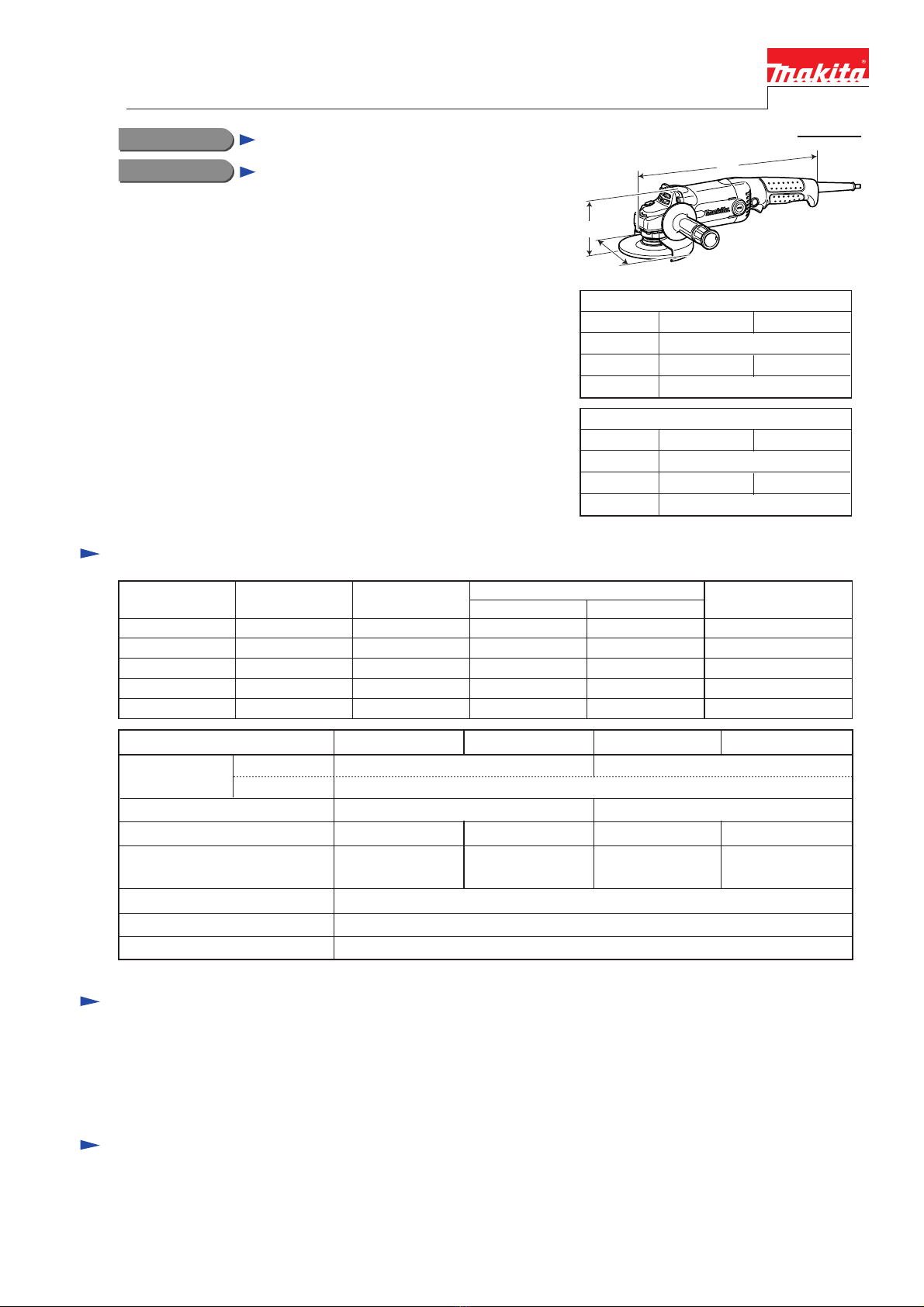
GA5020/ GA6020: Apply Makita Grease SG No.0 to the portions designated with the mark of . (Fig. 1)
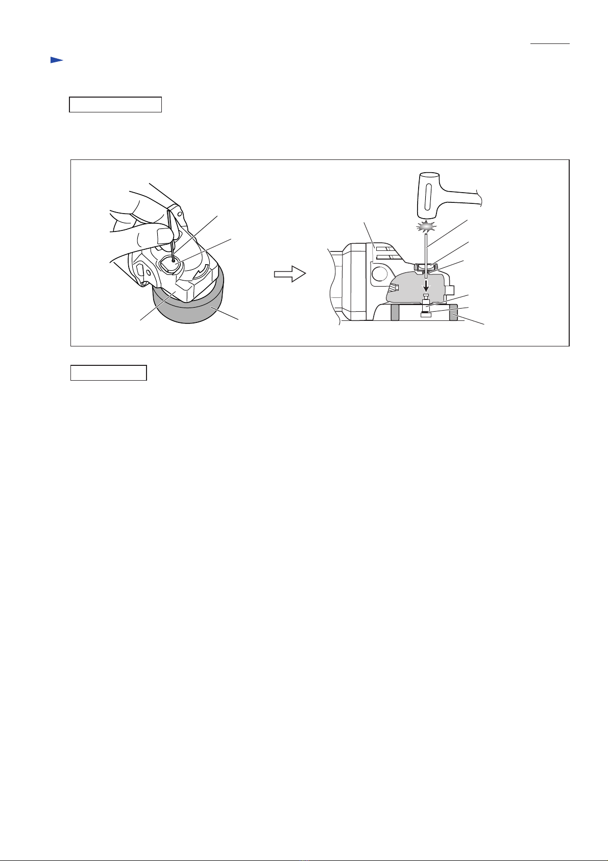
[3] DISASSEMBLY/ASSEMBLY
[1] NECESSARY REPAIRING TOOLS
[3] -1. Armature, Small spiral bevel gear*3, Ball bearing 6000DDW
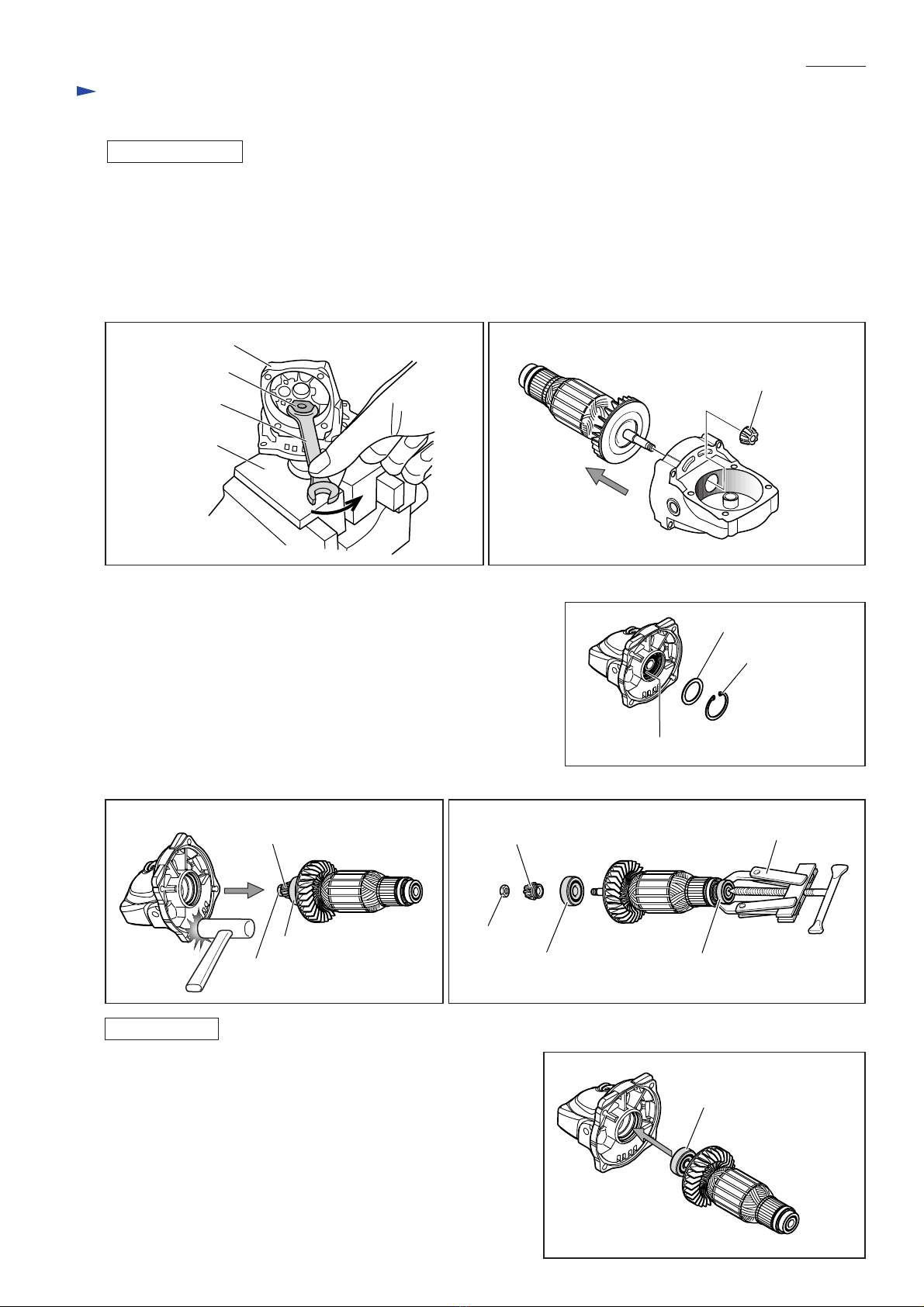
DISASSEMBLING Fig. 2
Pan head screw
M5x18 (4pcs)
Tapping screw
5x25 (4pcs)
1) After removing Carbon brush, separate Gear housing
together with Armature from Motor housing complete
by unscrewing four M5x18 Pan head screws. (Fig. 2)
2) Separate Bearing box from Gear housing by unscrewing
four 5x25 Tapping screws. (Fig. 2)
CAUTION: Unplug the machine and remove the wheel and the wheel cover from the machine
for safety before repair/ maintenance in accordance with the instruction manual!
Code No.
1R004
Description
Retaining ring pliers ST-2
[1R291 can be used instead of 1R004.]
Removal/installation of Ring spring 11 (GA5010/GA6010)
Removal/installation of Ring spring 7 (GA5020/GA6020)
1R005 Retaining ring pliers RT-2N Removing Retaining ring R-30
Installation of Large spiral bevel gear*1(GA5010/GA6010)
1R030 Bearing setting pipe 25-17.2
1R036 Bearing setting plate 17.2
Removal/installation of Hex nut M7
Removing Large spiral bevel gear (GA5010/GA6010)
Disassembling Shaft lock section
1R039 Armature holder 41.5 [one set required]
1R258 V block [2pcs required]
1R268 Spring pin extractor M3
1R269 Bearing extractor
Removing Lock sleeve and Lock spring 16--- Adjustable wrench
Removal/installation of Hex nut M7--- Wrench 11
Disassembling Shaft lock section1R350 Ring 60
Use for
Fig. 1
Large spiral bevel gear*2
Outside surface
Lock spring 1639
Surface that contacts Large spiral bevel gear*1
Spindle49
Item No. Description Portion to lubricate
39
49
Bearing box
Motor housing
complete
Gear housing
*2: Different spiral bevel gears are used
by different models as follows:
GA5020/ Spiral bevel gear 34B
GA6020/ Spiral bevel gear 35B
*3: Different spiral bevel gears are used
by different models as follows:
GA5010 and GA5020/ Spiral bevel gear 13
GA6010 and GA6020/ Spiral bevel gear 11
Removing Ball bearing 696ZZ
*1: Different spiral bevel gears are used by different models
as follows:
GA5010/ Spiral bevel gear 34A
GA6010/ Spiral bevel gear 35A

P 3 / 9
Repair
[3] -1. Armature, Small spiral bevel gear, Ball bearing 6000DDW (cont.)
DISASSEMBLING
ASSEMBLING Fig. 8
Ball bearing 6000DDW
1) Mount Ball bearing 6000DDW on Armature by hand, then insert
into the bearing installation hole of Gear housing, (Fig. 8)
Then pull off Armature.
2) Put Flat washer 22 on Ball bearing 6000DDW, and fasten them
with Retaining ring R-30 using 1R005.
3) Then do the reverse of the disassembling steps.
1R269
Ball bearing 608DDW
3) Attach one set of 1R039 to vise, then fix Armature in 1R039.
Remove Hex nut M7 from the drive-end of Armature shaft by turning it counterclockwise with Wrench 11. (Fig. 3)
4) Hold Small spiral bevel gear by hand, then pull off Armature from Gear housing. (Fig. 4)
Note: If it is difficult to pull off Armature by hand, do the following steps.
1. Lubricate the gear and Armature shaft with spray lubricant.
2. Wrap the gear with cloth to protect the gear teeth.
3.
Using water pump pliers or the like, firmly grip the gear wrapped with cloth, then turn the gear.
5) In order to remove Ball bearing 6000DDW from Gear housing,
first remove Retaining ring R-30 using 1R005, then remove
Flat washer 20 from Gear housing. (Fig. 5)
6) Reassemble Armature to Gear housing, then the spiral bevel gear
to Armature shaft. Tighten Hex nut M7 provisionally by turning
clockwise. (Refer to Figs. 4, 3)
7) By tapping the end surface of Gear housing with plastic hammer,
Ball bearing 6000DDW can be removed together with Armature.
(Fig. 6)
8) Remove Ball bearing 608DDW from Armature using 1R269. (Fig. 7)
Small spiral bevel gear
Fig. 3 Fig. 4
Hex nut M7 Small spiral bevel gear
Gear housing
Wrench 11
1R039
Fig. 6 Fig. 7
Hex nut M7
Ball bearing 600DDW
Ball bearing 6000DDW
Fig. 5
Retaining rig R-30
Flat washer 22
Ball bearing 6000DDW
Hex nut M7
Small spiral bevel gear

P 4 / 9
Repair
[3] -2. Large spiral bevel gear*3and Ball bearing in Bearing box*4
DISASSEMBLING
GA5010/ GA6010
All Models
Fig. 11 Fig. 12
Fig. 9 Fig. 10
3) Remove Ring spring 11 from Spindle by levering up with slotted screwdriver while expanding the ends of the spring
a little bit with 1R004 or 1R291. (Fig. 11)
4) As illustrated in Fig. 12, put 1R258 (2 pcs) on the table of arbor press, then fix Bearing box in 1R258; at this time,
make sure that 1R258 is securely supporting all of the three raised portions on the flanged end of Bearing retainer.
Remove Large spiral bevel gear by pressing down the end surface of Spindle using arbor press.
1) Separate Bearing box from Gear housing first by unscrewing four M5x18 Pan head screws then by tapping the end of
Gear housing with plastic hammer as illustrated in Fig. 9. It is not necessary to remove Carbon brushes.
2) Remove Ball bearing 6000ZZ using 1R269. (Fig. 10)
[Regarding steps 3) and 4), do the alternative steps depending on the models as described below.]
Note: The gear and the ball bearing can be replaced without disassembling the Motor section.
1R269
Ball bearing 696ZZ
Bearing box
Large spiral bevel gear
*3: Different spiral bevel gears are used by different models as follows:
GA5010/ Spiral bevel gear 34A, GA5020/ Spiral bevel gear 34B
GA6010/ Spiral bevel gear 35A, GA6020/ Spiral bevel gear 35B
*4: Different ball bearings are used by different models as follows:
GA5010 and GA6010/ Ball bearing 6202DDW
GA5020 and GA6020/ Ball bearing 6002DDW
Gear housing
Bearing box
1R004
Ring spring 11 Spindle
Slotted screwdriver
Bearing box,
viewed from bottom
raised portion
on the flanged end
1R258
Bearing box
Spindle Large spiral bevel gear

P 5 / 9
Repair
[3] -2. Large spiral bevel gear and Ball bearing in Bearing box (cont.)
DISASSEMBLING
GA5020/ GA6020
Fig. 13 Fig. 14
3) Remove Ring spring 7 from Spindle by levering up with slotted screwdriver while expanding the ends of the spring
a little bit with 1R004 or 1R291. (Refer to Fig. 11 on page 4.) Then remove Flat washer 8 and Lock washer.
4)-1. By striking the end surface of Spindle against workbench, Large spiral bevel gear can be removed from Spindle
together with Lock sleeve and Lock spring 16. (Fig. 13)
4)-2. Hold Large spiral bevel gear securely by hand, and pull off Lock sleeve with adjustable wrench while turning it
counterclockwise. Then remove Lock spring 16 the same way as you removed Lock sleeve. (Fig. 14)
Fig. 16 Fig. 17
Ball bearing
in Bearing box
5) After removing Large spiral bevel gear, separate Bearing retainer 39
by removing three M3x6 Pan head screws. (Fig. 15)
6) Remove Ball bearing in Bearing box by hitting Bearing box straight
down against flat surface of work-bench. (Fig. 16)
If cannot be removed, use arbor press and a round bar for arbor of
an appropriate size as illustrated in Fig. 17.
Fig. 15
Pan head screw
M3x6 (3 pcs)
Bearing retainer 39
Round bar for arbor
Bearing box
Spindle
Large spiral
bevel gear
All Models
Large spiral bevel gear
Lock sleeve
Lock spring 16

P 6 / 9
Repair
[3] -2. Large spiral bevel gear and Ball bearing in Bearing box (cont.)
ASSEMBLING
GA5020/ GA6020
Large spiral bevel gear
Lock spring 16
Fig. 18
Fig. 19
GA5010/ GA6010
Note 1: Ball bearing 6202DDW is damaged whenever Large spiral bevel gear is removed from Spindle.
Be sure to replace the Ball bearing with new one.
Note 2: If Ring spring 11 gets loose, be sure to replace with new one.
Note 3: Use 1R036, 1R030 and arbor press when assembling Large spiral bevel gear to Spindle. (Fig. 18)
Note 1: Ring spring 7 inevitably loses its elasticity when removed from Spindle. This will also happen to new one when
it is assembled to Spindle. Therefore, reuse removed Ring spring 7 if it is not damaged.
Do not forget to fasten Ring spring 7 securely to Spindle using pliers whether it is removed one or new one.
Note 2: Do as described in Fig. 19 when assembling Lock spring 16 and Lock sleeve to Large spiral bevel gear.
Do the reverse of the disassembling steps.
1R036
Bearing box
Spindle
Large spiral
bevel gear
1R030 arbor press
Put Lock spring 16 on the hole of Large spiral bevel gear,
then tap the top of the spring with plastic hammer
while gradually moving the impact point counterclockwise
until the spring does not move any further.
Put Lock sleeve over Lock spring 16, then tap the top
of the sleeve with plastic hammer as illustrated below
while gradually moving the impact point clockwise
until the sleeve does not move any further.
Lock sleeve

P 7 / 9
Repair
[3] -3. Shaft lock section
1) Remove Bearing box from Gear housing. (Fig.9on page 4)
2) Shoulder pin 5 can be removed from Gear housing using 1R268, 1R350 and plastic hammer as illustrated in Fig. 20.
DISASSEMBLING
Do the reverse of the disassembling steps.
Note: Do not reinstall removed Pin cap because removal of Shoulder pin 5 damages the inside surface of Pin cap.
Be sure to remove plastic dust of Pin cap from Shoulder pin 5 and to install it onto new Pin cap.
ASSEMBLING
Fig. 20
Pin cap
Gear housing
Shoulder pin 5
Compression spring 8
1R350
1R268
Pin cap
Gear housing
O ring 7
1R268
1R350

P 8 / 9
Circuit diagram
Field
*Noise suppressor is not used for some country.
Switch
Color index of lead wires' sheath
When Terminal block is used
Fig. D-1
When Terminal block is not used
Fig. D-2
Fig. D-3
Black
Power supply cord
Field
Switch
Power supply cord
Terminal block
White
Orange
Yellow
Color index of lead wires' sheath
Black
Noise suppressor*
Wiring diagram
[1] Motor housing
Route Field lead wires as illustrated below. (Fig. D-3)
Field lead wire
(yellow/orange
or black/white)
Lead wire from
Brush holder
(if used)
Motor housing

P 9 / 9
Switch
Fig. D-4
Fig. D-5
Terminal block
Noise suppressor
(if used)
Wiring diagram
[2] Handle
When Terminal block is used
When Terminal block is not used
Put Noise suppressor
in this portion if used.
Fix the following lead wires with Lead wire holder:
*two Field lead wires (yellow, orange)
*one Lead wire (black) from Brush holder
Bend Insulated terminals on the Lead wires
connected to Switch in order to prevent them
from touching the inside wall of Handle.
Put Terminal block
in this portion.
Lead wire holder
Insulated terminal
Insulated terminal Handle
Switch
Fix the following lead wires with Lead wire holder:
*two Field lead wires (black, white)
*two Lead wires (white) of Noise suppressor (if used)
Bend Insulated terminals on the Lead wires
connected to Switch in order to prevent them
from touching the inside wall of Handle.
Lead wire holder
Insulated terminal
Insulated terminal Handle
Other manuals for GA5010
5
This manual suits for next models
3
Table of contents
Other Makita Grinder manuals

Makita
Makita DGA406 User manual

Makita
Makita GA5041RZ User manual

Makita
Makita 9556HP User manual

Makita
Makita DGA419 User manual

Makita
Makita GA7030R User manual

Makita
Makita GA4030 Setup guide

Makita
Makita GA5080 User manual

Makita
Makita DGD800Z User manual

Makita
Makita GE0600 Quick start guide

Makita
Makita GA5020C User manual

Makita
Makita GA7060R User manual

Makita
Makita DGA700 User manual

Makita
Makita GD0601 User manual

Makita
Makita GS5000 User manual

Makita
Makita M0910B Operating instructions

Makita
Makita 9558HN User manual

Makita
Makita DGA402 User manual

Makita
Makita GA038G User manual

Makita
Makita GA4030 User manual

Makita
Makita BGA402 User manual