manuals.online logo
Brands
  1. Home
  2. •
  3. Brands
  4. •
  5. Makita
  6. •
  7. Impact Driver
  8. •
  9. Makita DTD148 User manual

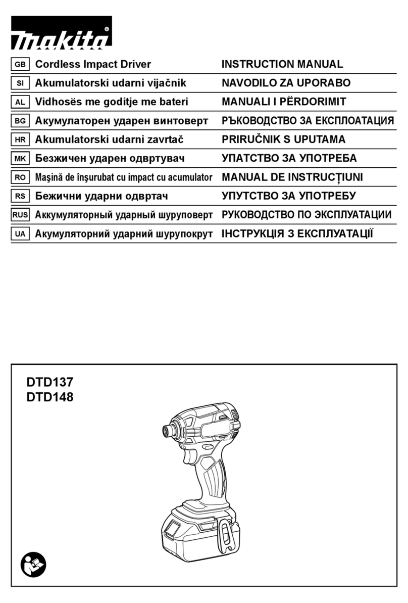
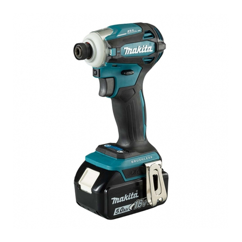
Makita DTD148 User manual

Dimensions: mm (")
Width (W)
Height (H)
Length (L) 119 (4-11/16)
79 (3-1/8)
220 (8-5/8)*1
238 (9-3/8)*2
*1 With Battery BL1815, BL1815N
or BL1820
*2 With Battery BL1830, BL1840
or BL1850
W
H
L
PRODUCT
TECHNICAL INFORMATION
Model No.
Description
P 1/ 14
DTD148
Cordless Impact Driver
CONCEPT AND MAIN APPLICATIONS
Specification
Standard equipment
Optional accessories
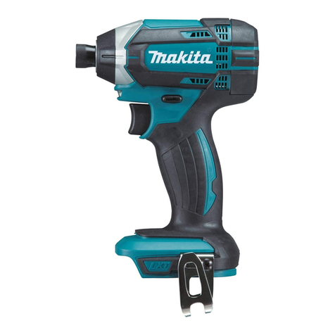
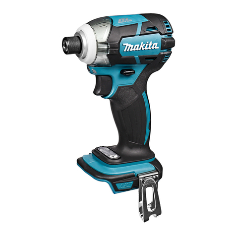
Model DTD148 Cordless Impact Driver is an advanced version
of the current model DTD147.
It features more compact body (overall length: 119mm) and
higher power than DTD147 while having the following same
benefits as the current model:
• Brushless motor
• Electronic 3-stage impact power selection
with variable power control in each range
• XPT (eXtreme Protection Technology) for use in outdoor
applications or harsh environments
• T-mode (Tightening mode for self-drilling screw)
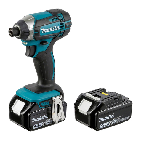
This product is compatible with 18V- 1.3Ah, 1.5Ah, 2.0Ah, 3.0Ah, 4.0Ah or
5.0Ah Li-ion batteries
BL1815, BL1815N, BL1820, BL1830, BL1840 or BL1850.
Battery
No load speed: min.ˉ¹=rpm
Impacts per min.: min.ˉ¹=ipm
Max. tightening torque*3: N.m [kgf.cm] (in.lbs)
Charging time (approx.): min.
Capacities
Electric brake
Reverse switch
Weight according to EPTA-Procedure 01/2003: kg (lbs)
Variable speed control by trigger
Capacity: Ah
Cell
Voltage: V 18V
0 - 3,600/ 2,100/ 1,100
0 - 3,800/ 2,600/ 1,100
175 [1,780] (1,550)
Standard bolt
High tensile bolt
Machine screw
Driving shank
M5 - M16 (3/16 - 5/8")
M5 - M14 (3/16 - 9/16")
Coarse-thread 22 - 125mm (7/8 - 4-7/8")
M4 - M8 (5/32 - 5/16")
Yes
Yes
Yes
LED job light Yes
1.2 (2.8)*4/ 1.5 (3.3)*5
1.3, 1.5, 2.0, 3.0, 4.0, 5.0
Energy capacity: Wh 24, 27, 36, 54, 72, 90
Li-ion
290
15, 15, 24, 22, 36, 45 with DC18RC
6.35mm (1/4") Hex
Max output (W)
*3 Tightening torque at 3 seconds after seating, when tightening M16 (grade 10.9) high strength bolt.
*4 With Battery BL1815,BL1815N or BL1820
*5 With Battery BL1830,BL1840 or BL1850
Phillips bits
Socket bits
Drill chucks
Drill bits with 6.35mm Hex shank
Hole saws for impact driver
Bit piece
Stopper for impact driver
Hook set (Belt clip)
Tool catcher set
Battery protectors
Li-ion Battery BL1850
Li-ion Battery BL1840
Li-ion Battery BL1830
Li-ion Battery BL1820
Li-ion Battery BL1815N
Li-ion Battery BL1815
Charger DC18SD
Charger DC24SC
Fast charger DC18RC
Automotive charger DC18SE
Four port multi charger DC18SF
Impact power selection Electronic 3 stage (Hard/ Medium/ Soft)
+ Teks screw mode
Hard/ Medium/ Soft
Hard/ Medium/ Soft
Belt clip
Battery*6, Battery cover*7
Charger*6, Plastic carrying case Note: The standard equipment may vary by country or model variation.
*6 Battery and charger are not supplied with “Z” model
*7 Supplied with the same quantity of extra Battery
OFFICIAL USE
for ASC & Sales Shop
PI / SC / NP 海外営業管理承認
Repair
[1] NECESSARY REPAIRING TOOLS
CAUTION: Repair the machine in accordance with “Instruction manual” or “Safety instructions”.
[2] LUBRICATION
Apply Makita grease FA. No.2 to the following portions designated with the black triangle to protect
parts and product from unusual abrasion.
Fig. 1
Item No.
21
27
19
Description
Nylon washer 24
Hammer
Flat washer 24*
(1mm thickness/ Heat treated plate)
Flat washer 24*
(0.5mm thickness)
*They have the same inner diameter and outer diameter.
Spur gear 22
Compression spring 25
Hammer case complete
AmountPortion to lubricate
25
19 Anvil a little
a little
a little
approx. 2 g
21 Steel ball 3.5
Steel ball 5.6
In the accepting hole for Rotor
Drum portion
whole portion
whole portion
Spindle
25
27
In the accepting hole for 27 Spindle
b
a
b
a
Code No. Description Use for
1R041 Holding Socket 32-50 when disassembling Hammer case
1R045 Disassembling/assembling Hammer section
1R223
1R224 Disassembling Hammer case (Use with 1R223.)
1R232 Holding Anvil when disassembling Bit holder section
1R288
1R291
134847-1 Disassembling/assembling Hammer case
134848-9 Disassembling/assembling Hammer case
P 2/ 14
Disassembling Hammer caseTorque wrench shaft 20-90 N·m
Gear extractor
Vise plate
Ratchet head 12.7
Pipe 30
Magnetizing a screwdriver for easy removal of steel ballsScrewdriver magnetizer
Removing Ring spring 11 of Bit holder sectionRetaining ring S & R Pliers
Socket 30-78
Socket 32-50
[3] DISASSEMBLY/ASSEMBLY
[3] -1. Hammer case complete
2. Remove Hammer case cover from Hammer case complete
by detaching the claws of Hammer case cover from the grooves
of Hammer case complete with thin slotted screwdriver.
3. Remove Rear cover by unscrewing two 3x16 Tapping screws.
And then, remove Housing set R by unscrewing eight 3x16
Tapping screws.
4. Remove the entire of Motor section and
Hammer case section from Housing set L.
5. Pull out Hammer case section
from Rotor shaft.
1. Remove Bumper with a thin slotted
screwdriver.
Fig. 2
Bumper Thin slotted
screwdriver
3x16 Tapping screw (2 pcs.)
Bumper
(1) Pull out Hammer case section from Rotor shaft as drawn in Fig. 2.
DISASSEMBLING
Thin slotted screwdriver
Hammer case cover Hammer case cover
Rear cover
Housing set R
Hammer case
complete
Motor section
Hammer
case section
Hammer
case section
Rotor shaft
Repair
P 3/ 14
3x16 Tapping screw
(8 pcs.)
[3] DISASSEMBLY/ASSEMBLY
[3] -1. Hammer case complete (cont.)
Fig. 3
(2) Disassemble Hammer case section. (Fig. 3)
Bearing box complete
Socket 32-50
(134848-9)
Socket 30-78
(134847-1)
1R041
Vise
Hammer case complete
1R224
1. Fit the hexagonal
portion into that of
Socket 32-50
(134848-9).
2. Fit Socket 30-78 (134847-1) to
the hexagonal portion of Hammer
case complete.
4. Now, Hammer case section is disassembled as drawn below.
1R223
3. Turn 1R223 clockwise.
Hammer case complete
Hammering mechanism
Internal gear 51
O ring 40
Bearing box
complete
DISASSEMBLING
Repair
P 4/ 14
[3] DISASSEMBLY/ASSEMBLY
[3] -1. Hammer case complete (cont.)
ASSEMBLING
(1) Assemble Hammer case section. (Figs. 4, 5, 6 and 7 )
(2) Mount Hammer case section to Housing in the reverse order of disassembly. (Fig. 2)
(3) Assemble Bumper to the machine. (Fig. 8)
groove of
Bearing box complete
Socket 32-50
(134848-9)
Bearing box
complete
Hammer
section
Hammer case
complete
Spur gear 22
stopper portion
1. While engaging Spur gear 22
with Internal gear 51,
set Hammer section in place.
Fig. 4
Fig. 6 Fig. 7
Fig. 8
Fig. 5
Hammer case complete,
viewed from bottom
Internal gear 51
stopper portion
Hammer case
complete
Socket 32-50
(134848-9)
Turn 1R223 counterclockwise.
Note: The fastening torque must
be 45 to 55 N·m.
(460 ~ 560 kgfcm)
Projection of Internal gear 51
Bearing box complete
1R224
Hammer case complete
Socket 30-78 (134847-1)
1. Put O ring 40 into the groove
of Bearing box complete.
2. Align the stopper portion of
Hammer case complete with
either one of the 4 projections
of Internal Gear 51, then put
Hammer case complete over
Bearing box complete.
Inner projection
Hammer case cover
Inner projection
Inner notch
Hole
Hole
claw
Bumper
Mount Bumper to Hammer case cover by
engaging four inner projections with four
corresponding holes, and two inner notches
with two corresponding claws.
Claw
2. Put the small diameter
portion of Internal gear 51
on O ring 40 in Bearing
box complete.
Repair
P 5/ 14
[3] DISASSEMBLY/ASSEMBLY
[3] -2. Rotor
Fig. 9
1. Put the Motor section on a workbench so that the drive end of Rotor touches the workbench.
Then separate Stator complete from Rotor by pulling it down towards the workbench.
Stator complete
Rotor
(1) Remove Bumper and Hammer case cover. Then, after removing Housing (R), separate Motor section from Hammer
case section. (Fig. 2)
(2) Rotor can give damage on the coil of Stator complete when pulling it off from Stator complete because Rotor attracts
Stator complete with its very strong magnetic force.
Therefore, Rotor must be removed from Stator complete as drawn in Fig. 9 to protect Stator complete from damage.
DISASSEMBLING
Caution for Handling of Rotor
When handling or storing multiple Rotors, be sure to keep a proper distance between Rotors as shown in Fig. 10.
Because Rotor is a strong magnet, failure to follow this instruction could result in:
Finger injury caused by pinching between Rotors pulling each other
Magnetic loss of Rotors or damage on the magnet portion of Rotor. (Fig. 11)
Fig. 10 Fig. 11
Wrong
* Magnetic loss of Rotors
* Damage on the magnet portion of Rotor
Repair
P 6/ 14
[3] DISASSEMBLY/ASSEMBLY
[3] -2. Rotor (cont.)
ASSEMBLING
(1) Assemble Rotor as drawn in Fig. 12
.
Fig. 12
Rotor
Stator complete
(2) Mount Motor section to Hammer case section. (Fig. 13)
Before pushing Motor section fully
in Hammer case section, make sure
that Rotor’ gear engages with the
two planet gears (Spur gear 22) of
Hammer case section to rotate
Spindle smoothly.
Fig. 13
Hammer case section
Motor section
2. When the drive end of Rotor
reaches workbench, lift up
Stator complete slowly.
1. Holding Stator complete on
workbench, slowly insert Rotor
in Stator complete until Rotor’s
drive end reaches workbench.
Repair
P 7/ 14
[3] DISASSEMBLY/ASSEMBLY
[3]-2. Bit Holder Section and Anvil
DISASSEMBLING
(1) Disassemble Hammer case section from the machine as drawn in Fig. 2.
(2) Disassemble Bearing box from Hammer case complete, then take out Internal gear 51 and Hammering mechanism
as drawn in Fig. 3.
(3) Disassemble Bit holder section and Anvil as drawn in Figs. 14, 15 and 16.
Steel ball 3.5 (2 pcs.)
Compression spring 13
Flat washer 12
Sleeve
Hammer case complete
Nylon washer 14 Anvil
Anvil
Sleeve
Hammer case
complete
Anvil
Use 1R232 for holding Sleeve firmly
for easy removal of Ring spring 11.
1R232
Ring spring 11
1R232
Fig. 14 Fig. 15
Fig. 16
Ring spring 11
Sleeve
Raise this side (opposite to the expanded side) with index finger
when removing Ring spring 11.
Press the top of Sleeve with
thumb so as not to allow
Compression spring 13 to
pop out and away.
Expand the end gap of
Ring spring 11 with 1R291.
Flat washer 12, Compression spring 13 and
Sleeve can now be removed from Anvil.
Anvil and Nylon washer 14 can now be removed from
Hammer case complete.
Be careful not to lose two Steel balls 3.5.
Repair
P 8/ 14
[3] DISASSEMBLY/ASSEMBLY
[3] -4. Mounting Hammer case section, Motor section and Switch to Housing (L)
1. Assemble F/R change lever to Switch by fitting the prong of
F/R change lever to the projection of Switch.
2. Set Switch to Housing set L straight and carefully so that the seal
of Switch does not move from the proper position.
ASSEMBLING
(1) Assemble Stator unit and Hammer case complete to Housing set L as drawn in Fig. 17.
(2) Assemble Switch, F/R change lever and Switch plate complete as drawn in Fig. 18.
Fig. 17
Fig. 18
Fit two depressions of Stator unit to two projections of Housing set L, and fit
the projection of Hammer case complete to the depression of Housing set L.
Two depressions of Stator unit
Two projections of Housing set L
Projection of Hammer case complete
Depression of Housing set L
Face the stopper of Hammer case complete toward Switch side.
Prong of
F/R change
lever
Switch plate
complete
Face the round mark side of
Switch plate complete to
Housing set L.
Housing set L
Projection
of Switch round mark
Repair
P 9/ 14
Stopper of Hammer case complete
The other projection of Hammer case complete and
the other depressions of Stator complete should be
fit to Housing set R.
[3] DISASSEMBLY/ASSEMBLY
[3]-5. Hammer section
DISASSEMBLING
(1) Disassemble Hammer case section from the machine as drawn in Fig. 2.
(2) Disassemble Bearing box from Hammer case complete, then take out Internal gear 51 and Hammering mechanism
as drawn in Fig. 3.
(3) The Hammering mechanism can be disassembled as drawn in Figs. 19, 20, 21 and 22.
Pin 5
Spindle
Hammer
Flat washer 24
Compression
spring 25
Flat washer 24
Steel ball 3.5
(24 pcs.)
Spindle section
Hammer section can now be disassembled as shown below. After removing Flat washer 24,
Steel balls 3.5 can be removed
from Hammer.
Fig. 19
Fig. 21 Fig. 22
Fig. 20
Hammer
1. Pull Hammer downwards using 1R045 to align
the opening for Steel ball insertion with the top of
the cam grooving on Spindle, and then remove
Steel balls 5.6 from Spindle.
Thin washer 15
Spur gear 22
Repair
P 10/ 14
2. Hold Hammer section as shown below in Fig. 20R,
and then release it from 1R045.
Caution: Do not hold Hammer section as shown below in
Fig. 20F when releasing Hammer section from
1R045. Failure to follow this instruction could
cause Steel balls 3.5 to fall out from Hammer.
Fig. 20R Fig. 20F
top of
cam groove
on Spindle
Spindle
Steel ball 5.6 (2pcs.)
Hammer
1R045
opening for
Steel ball
insertion
Circuit diagram
Fig. D-1
P 11/ 14
Blue
Yellow
White
Orange
Purple
Gray
Color index of lead wires' sheath
Black
Red
AS
Switch
Connector
Connector
LED circuit
Stator
Terminal
Fuse
Heat shrink tube
This Lead wire isThis Lead wire is red for some countries,
instead of white.
Controller
Wiring diagram
P 12/ 14
Fig. D-2
Wiring in Housing set L
Section A
Stopper of Hammer
case complete
Caution 1: Be careful not to pinch Lead wires of LED light circuit between
Stopper of Hammer case complete and Housing set.
After assembling Hammer case to Housing set L, set the Lead wires
of LED light circuit in place. Be careful about Cautions 1 and 2,
and the lead wires of LED light circuit will be put without being
pinched between Stopper of Hammer case complete and Housing set,
and between Rib E and Hammer case.
Caution 2: Be careful not to put
Lead wires of LED light circuit
between Rib E and Hammer case.
Slacking of Lead wires from Stator
unit should be placed
in this space.
Route Lead wires between
Rib C and Rib D.
Place Lead wires of LED light
circuit under Lead wires from
Stator unit.
Sponge attached to the Lead wires must
be placed so that it comes on the dotted
line as drawn above.
Do not put any Lead wires on these Ribs.
Route Lead wires from Terminal over the projection of Controller
on Housing L side.
Fixing Lead wires from Terminal
in this lead wire holder is allowed
if necessary.
Lead
wires
Rib E
Pass Lead wires of LED light circuit between Rib A and Boss,
between stopper of Hammer case and Rib B, and between Hammer
case and F/R change lever.
Stator unit
Rib C
Projection of Controller
Rib B
Rib A
Switch
F/R Change
lever
This dotted line means
the extension of the borderline
between Seal and Switch.
Do not move the seal from
the proper position.
(Refer to Fig. 18.)
Rib D
Hammer case
Stopper of
Hammer
case complete
Section A
Seal
LED light
circuit
Boss
Trouble shooting
Whenever you find any trouble in your machine, first, refer to this list to check the machine for solution.
(1) Use the full charged battery which has the star mark. (Fig. D-3)
(2) When Housing is disassembled, check the conditions of the electrical parts
(Connectors, Lead wires, Switches, etc.), Armature, Stator unit, Gear section, etc.
(3) Do the running test in Low speed mode (when the trigger is being pulled just a little)
to check the following functions by repeating 10 times;
• F/R change lever • Operation mode change ring • High/Low speed change lever
• Variable speed control trigger
Note in Repairing
Check List for Trouble Shooting
Motor runs when the machine
is switched on (in forward and
reverse mode;10 times each)
In case of running inconstantly,
go to “No”.
LED indicator lamps are on.
LED job light are on.
The machine does not
have any trouble.
Symptom Cause Corrective action
Rotation speed can be changed.
Forward/ Reverse rotation are OK.
Controller is broken. Replace Stator unit.
(See the next page.)
Connect it firmly.
Check Lead wires,
or replace it.
LED indicator lamps
are on.
Switch is broken.
Yes
Yes
Yes
Yes
Yes
No
No
No
No
No
Controller is broken.
Rotor is broken.
Stator unit is broken.
Replace Stator unit.
(See the next page.)
No
Controller is broken.
Connectors are in incomplete
connection.
Lead wires are broken.
Replace Stator unit
Check the items from the top of the following list. (Description of the item is referred to Circuit diagram in Fig. D-1.)
Change Stator unit if your problem cannot be solved although its corrective action has been carried out.
Check Terminal,
or replace it.
Replace Switch.
Replace Rotor.
Replace Stator unit.
Switch is broken. Replace Switch.
Connect it firmly.
Check Lead wires,
or replace it.
LED circuit is broken.
Connectors are in incomplete
connection.
Lead wires are broken.
Replace LED circuit.
Switch is broken. Replace Switch.
LED job light are on.
Rotor is rubbed to
Stator.
Yes
Yes
No
Connect it firmly.
Check Lead wires,
or replace it.
Connectors are in incomplete
connection.
Lead wires are broken.
Switch is broken. Replace Switch.
LED is broken. Replace LED.
Terminal is broken.
Star mark
Fig. D-3
P 13/ 14
Fig. D-4
Trouble shooting
Fig. D-4
Fig. D-6Fig. D-5
Test for recognizing the trouble on FET (Field effect transistor) in Controller
Set Digital tester (1R402) in the diode mode ( mark on the tester: Refer to Fig. D-4.)
Do the following steps.
Test 1: Attach Black tester bar to the plus pole of Terminal.
Attach Red tester bar to one of UVW terminal connected with Red, White, Blue lead wires.
Check the figure in the tester. (Fig. D-5)
Test 2: Attach Red tester bar to minus pole of Terminal.
Attach Black tester bar to one of UVW terminal connected with Red, White, Blue lead wires. (Fig. D-6)
There is no fault on FET of Controller if the tester indicates within 0.39V - 0.41V in both Test 1 and Test 2.
If either Test 1 or Test 2 results in the improper figure, Controller is broken. Change Stator unit.
P 14/ 14
Controller
UVW terminal
Stator
Terminal
1R402
1R402
Stator
Controller
UVW terminal
Terminal
Attach Tester bar (red) to any of UVW terminals
of Stator unit.
Attach Tester bar (black) to any of UVW terminals
of Stator unit.
Attach Tester bar (black) to Connector of
plus pole of Terminal.
Attach Tester bar (red) to Connector of
minus pole of Terminal.

Other manuals for DTD148

1

Other Makita Impact Driver manuals

Makita 6910 User manual

Makita

Makita 6910 User manual

Makita TD111DY1J User manual

Makita

Makita TD111DY1J User manual

Makita 6935FDWDE User manual

Makita

Makita 6935FDWDE User manual

Makita DTD152 User manual

Makita

Makita DTD152 User manual

Makita DTD170 User manual

Makita

Makita DTD170 User manual

Makita TD0101 User manual

Makita

Makita TD0101 User manual

Makita TD112D User manual

Makita

Makita TD112D User manual

Makita 6905B Quick start guide

Makita

Makita 6905B Quick start guide

Makita DTD134 User manual

Makita

Makita DTD134 User manual

Makita DTD154 User manual

Makita

Makita DTD154 User manual

Makita TD110D User manual

Makita

Makita TD110D User manual

Makita BTL060 User manual

Makita

Makita BTL060 User manual

Makita TD002G User manual

Makita

Makita TD002G User manual

Makita TW0200 User manual

Makita

Makita TW0200 User manual

Makita DTDA040 Series User manual

Makita

Makita DTDA040 Series User manual

Makita 6980FD User manual

Makita

Makita 6980FD User manual

Makita 6904VH User manual

Makita

Makita 6904VH User manual

Makita 6904VH User manual

Makita

Makita 6904VH User manual

Makita BTL062 User manual

Makita

Makita BTL062 User manual

Makita DTP141Z User manual

Makita

Makita DTP141Z User manual

Makita CX200RB User manual

Makita

Makita CX200RB User manual

Makita BTD141 Manual

Makita

Makita BTD141 Manual

Makita 6940D User manual

Makita

Makita 6940D User manual

Makita DT01 User manual

Makita

Makita DT01 User manual

Popular Impact Driver manuals by other brands

Skil PWRCORE 20 ID6739B-00 manual

Skil

Skil PWRCORE 20 ID6739B-00 manual

Facom NS.1010 instruction manual

Facom

Facom NS.1010 instruction manual

P.I.T. PIW1050-C Operation manual

P.I.T.

P.I.T. PIW1050-C Operation manual

King Canada 8044 Service manual

King Canada

King Canada 8044 Service manual

Jet JAT-126 Operations & parts manual

Jet

Jet JAT-126 Operations & parts manual

Chicago Pneumatic RP9582 instruction manual

Chicago Pneumatic

Chicago Pneumatic RP9582 instruction manual

Chicago Pneumatic CP772H-6 Operator's manual

Chicago Pneumatic

Chicago Pneumatic CP772H-6 Operator's manual

Ozito ZLIDS-012 instruction manual

Ozito

Ozito ZLIDS-012 instruction manual

Universal Tool UT8355-R Operator instructions

Universal Tool

Universal Tool UT8355-R Operator instructions

Chicago Pneumatic CP9540-B Series Operator's manual

Chicago Pneumatic

Chicago Pneumatic CP9540-B Series Operator's manual

Clarke CAT117 Operating & maintenance instructions

Clarke

Clarke CAT117 Operating & maintenance instructions

Paoli Avvitatori DP 176 Operating and maintenance manual

Paoli Avvitatori

Paoli Avvitatori DP 176 Operating and maintenance manual

SGS SAT110K owner's manual

SGS

SGS SAT110K owner's manual

Mammooth MMT A170 703 manual

Mammooth

Mammooth MMT A170 703 manual

Milwaukee M18 FMTIW2P12 Original instructions

Milwaukee

Milwaukee M18 FMTIW2P12 Original instructions

Black & Decker 5106173-00 instruction manual

Black & Decker

Black & Decker 5106173-00 instruction manual

Cornwell Tools bluePOWER CAT4282 operating manual

Cornwell Tools

Cornwell Tools bluePOWER CAT4282 operating manual

Black & Decker Fire Storm FS1202ID instruction manual

Black & Decker

Black & Decker Fire Storm FS1202ID instruction manual

manuals.online logo
manuals.online logoBrands
  • About & Mission
  • Contact us
  • Privacy Policy
  • Terms and Conditions

Copyright 2025 Manuals.Online. All Rights Reserved.