manuals.online logo
Brands
  1. Home
  2. •
  3. Brands
  4. •
  5. Makita
  6. •
  7. Nail Gun
  8. •
  9. Makita AN942 Manual

Makita AN942 Manual

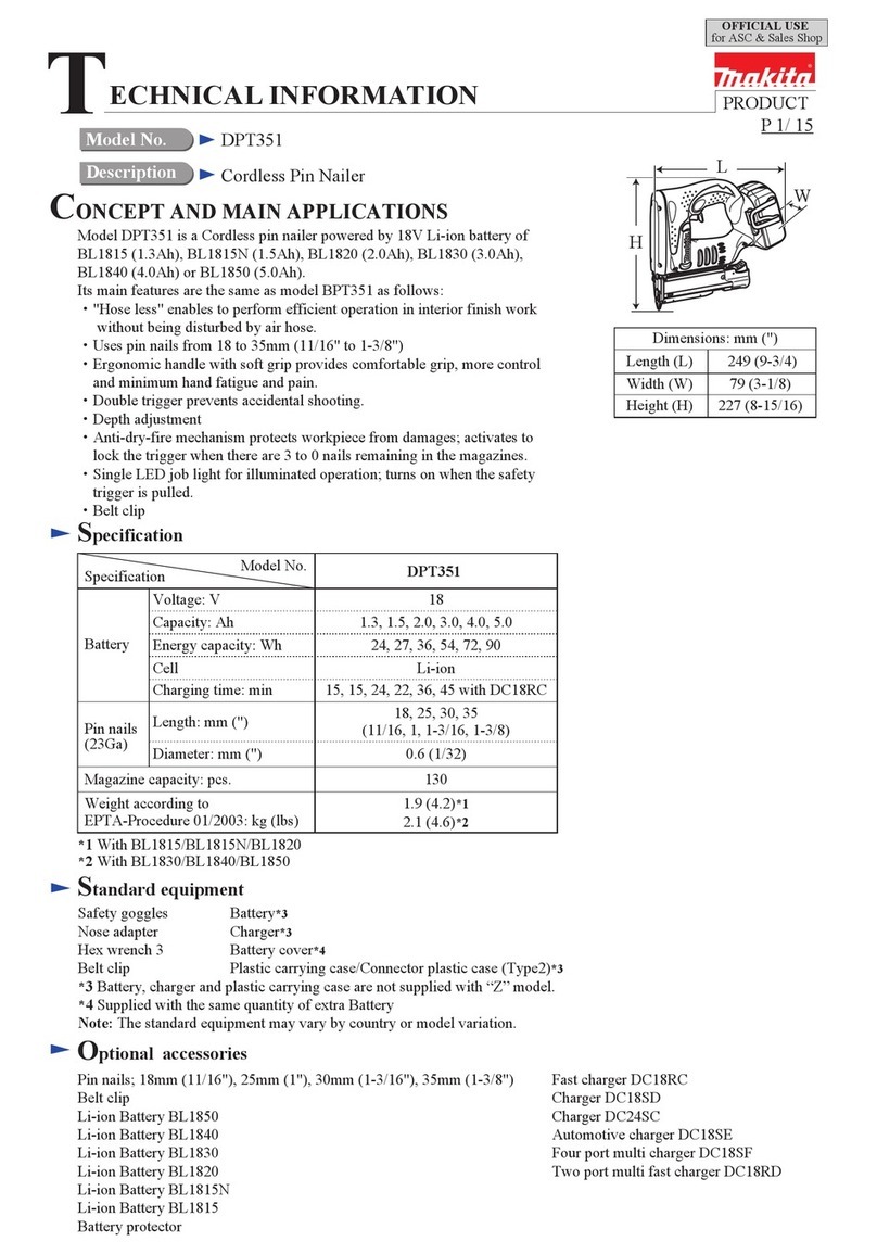
This model was developed as the more durable for
2 x 4 construction method.
Operating air pressure 0.44-0.83MPa ( 4.5 to 8.5 kgf/cm2G 65-120 PSIG)
Nail size 4.1mm in diameter and 90 mm in length
Nail capacities
Net Weight(kg)
Oiler (containing #90 turbine oil: 30cc)
Nose adaptor
Safety goggles
Specifications
Standard equipment
Optional accessories
CONCEPTION AND MAIN APPLICATIONS
Models No.
Product
TECHNICAL INFORMATION
Description
376mm (14-3/4")
446mm (17-1/2")
108mm (4-1/4")
AN942
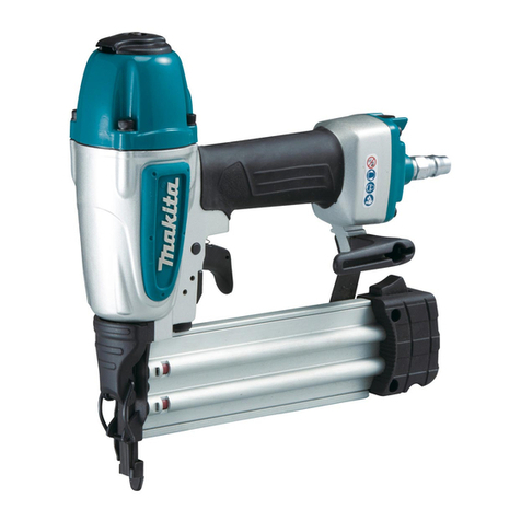
Makita Pneumatic construction nailer
The standard equipment for the tools shown may differ from country to country.
2.9mm in diameter and 50 mm in length
(0.113" in diameter and 2" in length)
60 - 84 nails
3.8 kg (8.4lbs)
(0.131" in diameter and 3/1/2" in length)
P 1 / 7
Repair
< 1 > General instruction.
< 2 > Disassembling head bulb section.
< 3> Assembling the head bulb section.
< 4 > Disassembling trigger section.
< 5 > Assembling magazine section.
< 6 > Attaching of driver complete.
< 7 > Repair to stop the leaking air.
Please refer to the following matters on the repair.
< 1> General instruction
I. O rings and O ring part which contacts the sliding parts, have to be coated
with turbine oil (standard equipment), or grease (Isolex NB52), when the machine is
mounted.
II. Please refer to the following parts name.
Exhaust cover
Top cap
Housing
Driver guide
Contact arm Pusher lever
Magazine
Joint
Inlet cap
Trigger
III. The bolts have to be fastened as follows.
Bolt and Bolt size Fastening section Fastening torque
Hex socket head bolt M6 x 25
Hex socket head bolt M5 x 30
Hex socket head bolt M8 x 25
Housing - Top cap
Housing - Inlet cap
Housing - Driver guide
9 - 13 Nm
(90 - 130 Kgf.cm)
5 - 7 Nm
(50 - 75 Kgf.cm)
20 - 30 Nm
(200 - 300 Kgf.cm)
IV. Confirm the following matters after mounting of the parts.
* Pusher can slide smoothly.
* Contact arm and trigger can move smoothly.
* Singly by pressing the trigger or contact arm, the machine does not start.
P 2 / 7
Repair P 3 / 7
< 2 > Disassembling head bulb section.
( 1 ) Unscrew 4 pcs. of hex socket head bolts M6x25 and separate top cap and top cap gasket from housing. See Fig. 1
( 2 ) Unscrew 3 pcs. of hex socket head bolts M5x10 and separate exhaust cover from top cap. See Fig. 1.
( 3 ) Strike the thin bar inserted in to the hole of top cap, then the following parts can be removed from top cap
as illustrated in Fig. 2.
* Head valve with valve seat, O ring 40 and O ring 56
* Cushion R with washer 34
* Compression spring 5
* Driver complete with O ring 49
( 4 ) Remove valve seat from head valve. See Fig. 3.
Fig. 1
Hex socket head
bolts M6x25 ( 4 pcs.)
Hex socket head
bolts M5x10 ( 3 pcs.)
Top cap
Top cap
Exhaust cover
Fig. 2
Head valve with
valve seat,
O ring 40 and
O ring 56
Compression
spring 5
Cushion R
with washer 34
Top cap gasket
For removing, lever up valve seat
with flat head screwdriver.
Head valve
Valve seat
Fig. 3
Fig. 4
Fig. 5
< 3 > Assembling the head bulb section.
( 1 ) Put washer 34 and cushion R into head valve. See Fig. 4.
( 2 ) Mount compression spring 50 and head valve section
to top cap. See Fig. 5.
Head valve Cushion R
Washer 34 Top cap
Compression
spring 50
Head valve section
assembled in Fig.4
(It has to be pushed into
head cap until the boss of cushion R
is engaged firmly with head cap.)
Boss of
cushion R
Repair P 4 / 7
< 4 > Disassembling the trigger section.
< 5 > Assembling the magazine section.
( 1 ) Remove spring pin 3-28 of No.1 and then, the same of No.2. See Fig. 6.
( 2 ) Remove the following parts from housing. See Fig. 6.
* Trigger valve case
* Trigger valve stem
* Compression spring 3
* Pilot valve
( 3 ) Unscrew 4 pcs. of hex socket head bolts M6x25 and separate top cap and top cap gasket from housing.
And then, remove trigger valve guide as illustrated in Fig. 7.
No.1 Spring
pin 3-28
No.2 Spring
pins 3-28
Trigger
Fig. 6 Fig. 7
Fig. 8
Trigger valve case
Trigger valve stem
Compression spring 3
Pilot valve
Hex socket head
bolts M6x25
Top cap
Trigger valve guide
Thin bar
Top cap
gasket
Pusher lever Magazine
( 1 ) Mount pusher lever to magazine. Push pusher lever in the direction shown with the black arrow,
and insert a bar into the hole of magazine to hold the pusher lever for easy assemble of
the magazine section. See Fig. 8.
a Bar
Repair P 5 / 7
( 2 ) Mount contact arm to driver guide. And the, mount magazine to housing. See Fig. 9.n
( 3 ) The hex socket head bolt for joint has to be fastened loosely at the first. Finally it has to be
tightened firmly.
Fig. 9
Fig. 10
Contact arm
Driver guide
Magazine section
< 6 > Mounting driver complete
Pass driver complete through driver guide with aligning. See Fig. 10.
Driver guide
Hole's figure
of driver guide Figure of
driver complete's rod
Driver complete
Fig. 12
Repair P 6 / 7
< 7 > Repair to stop the leaking air.
If the air leaks out from the portion shown in Fig. 11, when you connect the product with an air compressor, check or
replace the joint portion and sealing material ( O rings, gaskets etc.).
A
B
C
D
E
Fig. 11
Fig. 15
Fig. 16
Fig. 17
Fig. 18
Fig. 19
Fig. 20
A) Leaking from the exhaust
Check or replace the following parts.
See Fig. 12
* Valve seat
* O ring 40
C) Leaking from the trigger section
Check or replace the following parts.
See Fig. 14
* O ring 3 * O ring 12
* O ring 8 * O ring 18
D) Leaking from the joint of inlet cap and housing
Check or replace the following parts.
See Fig. 15
* Inlet cap gasket
* Hex socket head bolt M5x30
B) Leaking from the joint of housing and top cap
Check or replace the following parts.
See Fig. 13
* Top cap gasket
* Hex socket head bolt M6x25
Valve seat
O ring 40 Top cap
gasket
Hex socket
head bolts M6x25
(Fasten it firmly
if it is loose.)
Fig. 13
Fig. 14
O ring 3
O ring 12
O ring 8
O ring 18 Hex socket
head bolts M5x30
(Fasten it firmly
if it is loose.)
Inlet cap gasket
Repair P 7 / 7
A
B
C
D
E
Fig. 11
Fig. 16
O ring 87
O ring 60
E) Leaking from the top of driver guide
See Fig. 16
* O ring 87 on cylinder separator
* O ring 60 on cylinder
Cylinder separator
Cylinder

Other manuals for AN942

3

Other Makita Nail Gun manuals

Makita GF600 User manual

Makita

Makita GF600 User manual

Makita AN451 User manual

Makita

Makita AN451 User manual

Makita DBN500 User manual

Makita

Makita DBN500 User manual

Makita AN923 Quick start guide

Makita

Makita AN923 Quick start guide

Makita PT354D User manual

Makita

Makita PT354D User manual

Makita DPT353 User manual

Makita

Makita DPT353 User manual

Makita AN250HC User manual

Makita

Makita AN250HC User manual

Makita XNB01 User manual

Makita

Makita XNB01 User manual

Makita AN611 User manual

Makita

Makita AN611 User manual

Makita AN610H User manual

Makita

Makita AN610H User manual

Makita FN001G User manual

Makita

Makita FN001G User manual

Makita AN901 User manual

Makita

Makita AN901 User manual

Makita GN900 User manual

Makita

Makita GN900 User manual

Makita AN911H User manual

Makita

Makita AN911H User manual

Makita LXTP01 1 Series Manual

Makita

Makita LXTP01 1 Series Manual

Makita GF600 User manual

Makita

Makita GF600 User manual

Makita PT354D User manual

Makita

Makita PT354D User manual

Makita DBN500 User manual

Makita

Makita DBN500 User manual

Makita DBN500 User manual

Makita

Makita DBN500 User manual

Makita Gas nailer GN900SE User manual

Makita

Makita Gas nailer GN900SE User manual

Makita AN510H User manual

Makita

Makita AN510H User manual

Makita AN923 User manual

Makita

Makita AN923 User manual
Makita AF601 User manual

Makita

Makita AF601 User manual

Makita AN923 User manual

Makita

Makita AN923 User manual

Popular Nail Gun manuals by other brands
Parkside PET 25 B1 Operation and safety notes

Parkside

Parkside PET 25 B1 Operation and safety notes
Metabo HPT NR 83A5 Instruction and safety manual

Metabo HPT

Metabo HPT NR 83A5 Instruction and safety manual

Unimac LXG3000 user manual

Unimac

Unimac LXG3000 user manual

Meec tools 071015 operating instructions

Meec tools

Meec tools 071015 operating instructions

DeWalt D51238 manual

DeWalt

DeWalt D51238 manual

Parkside PAT 20-Li A1 Translation of the original instructions

Parkside

Parkside PAT 20-Li A1 Translation of the original instructions

Paslode IM250 II operating manual

Paslode

Paslode IM250 II operating manual

DeWalt DCN660 Original instructions

DeWalt

DeWalt DCN660 Original instructions

DeWalt D51180 instruction manual

DeWalt

DeWalt D51180 instruction manual

Bosch FNS250-16 Operating/safety instructions

Bosch

Bosch FNS250-16 Operating/safety instructions

JDV WG400 quick start guide

JDV

JDV WG400 quick start guide

Hitachi NP 18DSAL Instruction and safety manual

Hitachi

Hitachi NP 18DSAL Instruction and safety manual

Milwaukee M18 FN15GA Operator's manual

Milwaukee

Milwaukee M18 FN15GA Operator's manual

Grizzly T27338 owner's manual

Grizzly

Grizzly T27338 owner's manual

North American Tool Industries 7564 Important operating instructions

North American Tool Industries

North American Tool Industries 7564 Important operating instructions

Milwaukee M12 2458-20 Operator's manual

Milwaukee

Milwaukee M12 2458-20 Operator's manual

Parkside PHET 15 A1 Translation of the original instructions

Parkside

Parkside PHET 15 A1 Translation of the original instructions

Bostitch EHF1838K Operating and maintenance manual

Bostitch

Bostitch EHF1838K Operating and maintenance manual

manuals.online logo
manuals.online logoBrands
  • About & Mission
  • Contact us
  • Privacy Policy
  • Terms and Conditions

Copyright 2025 Manuals.Online. All Rights Reserved.