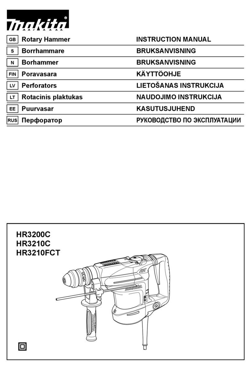
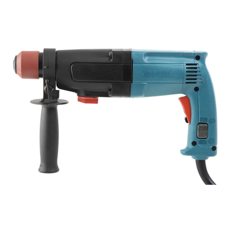
Makita HR2300 User manual

1
INSTRUCTION MANUAL
MANUEL D'INSTRUCTION
MANUAL DE INSTRUCCIONES
DOUBLE INSULATION
DOUBLE ISOLATION
DOBLE AISLAMIENTO
IMPORTANT: Read Before Using.
IMPORTANT: Lire avant usage.
IMPORTANTE: Leer antes de usar.
Rotary Hammer /
Combination Hammer
Marteau Perforateur /
Marteau Combi
Martillo Rotativo /
Martillo Rotativo Combinado
HR2300
HR2600
HR2610
HR2610T
HR2611F
HR2611FT
010712

2
ENGLISH (Original instructions)
SPECIFICATIONS
Model HR2300 HR2600 HR2610 HR2610T HR2611F HR2611FT
Concrete 23 mm (7/8") 26 mm (1")
Core bit
68 mm (2-11/16")
68 mm (2-11/16")
Steel 13 mm (1/2") 13 mm (1/2")
Capacities
Wood
32 mm (1-1/4")
32 mm (1-1/4")
No load speed (RPM) 0 - 1,200/min.
Blows per minute 0 - 4,600
Overall length
356 mm (14") 361 mm (14-1/4") 361 mm (14-1/4") 385 mm (15-1/8") 361 mm (14-1/4") 385 mm (15-1/8")
Net weight
2.7 kg (5.9 lbs) 2.8 kg (6.2 lbs) 2.8 kg (6.1 lbs) 2.9 kg (6.4 lbs) 2.9 kg (6.4 lbs) 3.0 kg (6.6 lbs)
• Due to our continuing program of research and development, the specifications herein are subject to change without notice.
• Specifications may differ from country to country.
• Weight according to EPTA-Procedure 01/2003
GEA008-1
General Power Tool Safety
Warnings
WARNING Read all safety warnings and all
instructions. Failure to follow the warnings and
instructions may result in electric shock, fire and/or
serious injury.
Save all warnings and
instructions for future reference.
The term "power tool" in the warnings refers to your
mains-operated (corded) power tool or battery-operated
(cordless) power tool.
Work area safety
1. Keep work area clean and well lit. Cluttered or
dark areas invite accidents.
2. Do not operate power tools in explosive
atmospheres, such as in the presence of
flammable liquids, gases or dust. Power tools
create sparks which may ignite the dust or fumes.
3. Keep children and bystanders away while
operating a power tool. Distractions can cause
you to lose control.
Electrical Safety
4. Power tool plugs must match the outlet. Never
modify the plug in any way. Do not use any
adapter plugs with earthed (grounded) power
tools. Unmodified plugs and matching outlets will
reduce risk of electric shock.
5. Avoid body contact with earthed or grounded
surfaces such as pipes, radiators, ranges and
refrigerators. There is an increased risk of
electric shock if your body is earthed or grounded.
6. Do not expose power tools to rain or wet
conditions. Water entering a power tool will
increase the risk of electric shock.
7. Do not abuse the cord. Never use the cord for
carrying, pulling or unplugging the power tool.
Keep cord away from heat, oil, sharp edges or
moving parts. Damaged or entangled cords
increase the risk of electric shock.
8. When operating a power tool outdoors, use an
extension cord suitable for outdoor use. Use of
a cord suitable for outdoor use reduces the risk of
electric shock.
9. If operating a power tool in a damp location is
unavoidable, use a ground fault circuit
interrupter (GFCI) protected supply. Use of an
GFCI reduces the risk of electric shock.
Personal Safety
10. Stay alert, watch what you are doing and use
common sense when operating a power tool.
Do not use a power tool while you are tired or
under the influence of drugs, alcohol or
medication. A moment of inattention while
operating power tools may result in serious
personal injury.
11. Use personal protective equipment. Always
wear eye protection. Protective equipment such
as dust mask, non-skid safety shoes, hard hat, or
hearing protection used for appropriate conditions
will reduce personal injuries.
12. Prevent unintentional starting. Ensure the
switch is in the off-position before connecting
to power source and/or battery pack, picking
up or carrying the tool. . Carrying power tools
with your finger on the switch or energising power
tools that have the switch on invites accidents.
13. Remove any adjusting key or wrench before
turning the power tool on. A wrench or a key left
attached to a rotating part of the power tool may
result in personal injury.
3
14. Do not overreach. Keep proper footing and
balance at all times. This enables better control
of the power tool in unexpected situations.
15. Dress properly. Do not wear loose clothing or
jewellery. Keep your hair, clothing, and gloves
away from moving parts. Loose clothes,
jewellery or long hair can be caught in moving
parts.
16.
If devices are provided for the connection of
dust extraction and collection facilities, ensure
these are connected and properly used.
Use of
dust collection can reduce dust-related hazards.
Power tool use and care
17. Do not force the power tool. Use the correct
power tool for your application. The correct
power tool will do the job better and safer at the
rate for which it was designed.
18. Do not use the power tool if the switch does
not turn it on and off. Any power tool that cannot
be controlled with the switch is dangerous and
must be repaired.
19. Disconnect the plug from the power source
and/or the battery pack from the power tool
before making any adjustments, changing
accessories, or storing power tools. Such
preventive safety measures reduce the risk of
starting the power tool accidentally.
20. Store idle power tools out of the reach of
children and do not allow persons unfamiliar
with the power tool or these instructions to
operate the power tool. Power tools are
dangerous in the hands of untrained users.
21. Maintain power tools. Check for misalignment
or binding of moving parts, breakage of parts
and any other condition that may affect the
power tool’s operation. If damaged, have the
power tool repaired before use. Many accidents
are caused by poorly maintained power tools.
22. Keep cutting tools sharp and clean. Properly
maintained cutting tools with sharp cutting edges
are less likely to bind and are easier to control.
23. Use the power tool, accessories and tool bits
etc. in accordance with these instructions,
taking into account the working conditions
and the work to be performed. Use of the power
tool for operations different from those intended
could result in a hazardous situation.
Service
24. Have your power tool serviced by a qualified
repair person using only identical replacement
parts. This will ensure that the safety of the power
tool is maintained.
25. Follow instruction for lubricating and
changing accessories.
26. Keep handles dry, clean and free from oil and
grease.
USE PROPER EXTENSION CORD. Make sure your
extension cord is in good condition. When using an
extension cord, be sure to use one heavy enough to
carry the current your product will draw. An undersized
cord will cause a drop in line voltage resulting in loss of
power and overheating. Table 1 shows the correct size
to use depending on cord length and nameplate ampere
rating. If in doubt, use the next heavier gage. The
smaller the gage number, the heavier the cord.
Table 1: Minimum gage for cord
Ampere Rating Volts Total length of cord in feet
120 V 25 ft. 50 ft. 100 ft. 150 ft.
More Than Not More Than AWG
0 6 18 16 16 14
18 16 14 12610
10 12 16 16 14 12
12 16 14 12 Not Recommended
000173

4
GEB007-7
ROTARY HAMMER SAFETY
WARNINGS
1. Wear ear protectors. Exposure to noise can
cause hearing loss.
2. Use auxiliary handle(s), if supplied with the
tool. Loss of control can cause personal injury.
3. Hold power tool by insulated gripping
surfaces, when performing an operation
where the cutting accessory may contact
hidden wiring or its own cord. Cutting
accessory contacting a "live" wire may make
exposed metal parts of the power tool "live" and
could give the operator an electric shock.
4. Wear a hard hat (safety helmet), safety glasses
and/or face shield. Ordinary eye or sun
glasses are NOT safety glasses. It is also
highly recommended that you wear a dust
mask and thickly padded gloves.
5. Be sure the bit is secured in place before
operation.
6. Under normal operation, the tool is designed
to produce vibration. The screws can come
loose easily, causing a breakdown or accident.
Check tightness of screws carefully before
operation.
7. In cold weather or when the tool has not been
used for a long time, let the tool warm up for a
while by operating it under no load. This will
loosen up the lubrication. Without proper
warm-up, hammering operation is difficult.
8. Always be sure you have a firm footing.
Be sure no one is below when using the tool in
high locations.
9. Hold the tool firmly with both hands.
10. Keep hands away from moving parts.
11. Do not leave the tool running. Operate the tool
only when hand-held.
12. Do not point the tool at any one in the area
when operating. The bit could fly out and
injure someone seriously.
13. Do not touch the bit or parts close to the bit
immediately after operation; they may be
extremely hot and could burn your skin.
14. Some material contains chemicals which may
be toxic. Take caution to prevent dust
inhalation and skin contact. Follow material
supplier safety data.
SAVE THESE INSTRUCTIONS.
WARNING:
DO NOT let comfort or familiarity with product
(gained from repeated use) replace strict adherence
to safety rules for the subject product. MISUSE or
failure to follow the safety rules stated in this
instruction manual may cause serious personal
injury.
USD202-2
Symbols
The followings show the symbols used for tool.
・volts
・amperes
・hertz
・alternating current
・no load speed
・Class II Construction
・revolutions or reciprocation per minute
・number of blow

5
FUNCTIONAL DESCRIPTION
CAUTION:
• Always be sure that the tool is switched off and
unplugged before adjusting or checking function on
the tool.
Switch action
1
2
010720
CAUTION:
• Before plugging in the tool, always check to see
that the switch trigger actuates properly and
returns to the "OFF" position when released.
To start the tool, simply pull the switch trigger. Tool
speed is increased by increasing pressure on the switch
trigger. Release the switch trigger to stop. For
continuous operation, pull the switch trigger, push in the
lock button and then release the switch trigger. To stop
the tool from the locked position, pull the switch trigger
fully, then release it.
Lighting up the lamps
For Models HR2611F, HR2611FT
1
010721
CAUTION:
• Do not look in the light or see the source of light
directly.
To turn on the lamp, pull the trigger. Release the trigger
to turn it off.
NOTE:
• Use a dry cloth to wipe the dirt off the lens of lamp.
Be careful not to scratch the lens of lamp, or it may
lower the illumination.
• Do not use thinner or gasoline to clean the lamp.
Such solvents may damage it.
Reversing switch action
B
A
1
010722
CAUTION:
• Always check the direction of rotation before
operation.
• Use the reversing switch only after the tool comes
to a complete stop. Changing the direction of
rotation before the tool stops may damage the tool.
• If the switch trigger can not be depressed, check to
see that the reversing switch is fully set to
position (A side) or (B side).
This tool has a reversing switch to change the direction
of rotation. Move the reversing switch lever to
the position (A side) for clockwise rotation or
the position (B side) for counterclockwise rotation.
Changing the quick change chuck for
SDS-plus
For Model HR2610T,HR2611FT only
The quick change chuck for SDS-plus can be easily
exchanged for the quick change drill chuck.
Removing the quick change chuck for SDS-plus
1
23
011561
CAUTION:
• Before removing the quick change chuck for
SDS-plus, always remove the bit.
Grasp the change cover of the quick change chuck for
SDS-plus and turn in the direction of the arrow until the
change cover line moves from the symbol to the
symbol. Pull forcefully in the direction of the arrow.
1. Quick change
chuck for
SDS-plus
2. Change cover
line
3. Change cover
1. Reversing
switch lever
1. Lamp
1. Switch trigger
2. Lock button

6
Attaching the quick change drill chuck
1
2
34
011562
Check the line of the quick change drill chuck shows the
symbol. Grasp the change cover of the quick change
drill chuck and set the line to the symbol.
Place the quick change drill chuck on the spindle of the
tool.
Grasp the change cover of the quick change drill chuck
and turn the change cover line to the symbol until a
click can clearly be heard.
Selecting the action mode
For Models HR2300, HR2600
1
23
010723
This tool employs an action mode changing knob. Select
one of the two modes suitable for your work needs by
using this knob.
For rotation only, turn the knob so that the arrow on the
knob points toward the symbol on the tool body.
For rotation with hammering, turn the knob so that the
arrow on the knob points toward the symbol on the tool
body.
CAUTION:
• Always set the knob fully to your desired mode
symbol. If you operate the tool with the knob
positioned halfway between the mode symbols, the
tool may be damaged.
• Use the knob after the tool comes to a complete
stop.
For Models HR2610,HR2610T, HR2611F, HR2611FT
Rotation with hammering
1
2
010724
For drilling in concrete, masonry, etc., rotate the action
mode changing knob to the symbol. Use a
tungsten-carbide tipped bit.
Rotation only
1
010726
For drilling in wood, metal or plastic materials, rotate the
action mode changing knob to the symbol. Use a
twist drill bit or wood bit.
Hammering only
1
010725
For chipping, scaling or demolition operations, rotate the
action mode changing knob to the symbol. Use a
bull point, cold chisel, scaling chisel, etc.
CAUTION:
• Do not rotate the action mode changing knob when
the tool is running under load. The tool will be
damaged.
• To avoid rapid wear on the mode change
mechanism, be sure that the action mode
changing knob is always positively located in one
of the three action mode positions.
• Do not force the action mode change knob or do
not move it from symbol mode to symbol
mode (or vise versa) at once. It may damage the
1. Hammering only
1. Rotation only
1. Rotation with
hammering
2. Action mode
changing knob
1. Rotation with
hammering
2. Rotation only
3. Action mode
changing knob
1. Spindle
2. Quick change
drill chuck
3. Change cover
line
4. Change cover

7
tool. When turning the knob from symbol mode
to symbol mode (or vise versa), stop it at
symbol mode once. And rotate the chuck clockwise
(looking from the chuck side) half turn or until it
clicks. Then turn the knob to the desired mode. If it
is still difficult to turn the knob, rotate the chuck
again.
Torque limiter
The torque limiter will actuate when a certain torque
level is reached. The motor will disengage from the
output shaft. When this happens, the bit will stop turning.
CAUTION:
• As soon as the torque limiter actuates, switch off
the tool immediately. This will help prevent
premature wear of the tool.
• Bits such as hole saw, which tend to pinch or catch
easily in the hole, are not appropriate for this tool.
This is because they will cause the torque limiter to
actuate too frequently.
ASSEMBLY
CAUTION:
•
Always be sure that the tool is switched off and
unplugged before carrying out any work on the tool.
Side grip (auxiliary handle)
1
2
010713
CAUTION:
•
Always use the side grip to ensure operating safety.
Install the side grip so that the protrusions on the grip fit
in between the grooves on the tool barrel. Then tighten
the grip by turning clockwise at the desired position. It
may be swung 360° so as to be secured at any position.
Bit grease
Coat the bit shank head beforehand with a small amount
of bit grease (about 0.5 - 1 g).
This chuck lubrication assures smooth action and longer
service life.
Installing or removing the bit
2
1
003150
Clean the bit shank and apply bit grease before installing
the bit.
1
010714
Insert the bit into the tool. Turn the bit and push it in until
it engages.
After installing, always make sure that the bit is securely
held in place by trying to pull it out.
To remove the bit, pull the chuck cover down all the way
and pull the bit out.
1
2
010715
Bit angle (when chipping, scaling or
demolishing)
For Models HR2610, HR2610T,HR2611F, HR2611FT
1
010727
The bit can be secured at the desired angle. To change
the bit angle, rotate the action mode changing knob to
1. Action mode
changing knob
1. Bit
2. Chuck cover
1. Bit
1. Bit shank
2. Bit grease
1. Protrusions
2. Grooves

8
the Osymbol. Turn the bit to the desired angle.
Rotate the action mode changing knob to the symbol.
Then make sure that the bit is securely held in place by
turning it slightly.
010728
Depth gauge
The depth gauge is convenient for drilling holes of
uniform depth.
12
3
010716
Press the lock button on the grip base in the direction of
arrow shown in the figure and with the lock button being
pressed insert the depth gauge into the hex. hole in the
grip base
2
1
010717
At this time, the depth gauge needs to be inserted so
that its toothed side is directed to the toothed side of hex
hole marking on the grip base as shown in the figure.
1
010718
Adjust the depth gauge to the desired depth by moving it
back and forth while pressing the lock button. After the
adjustment, release the lock button to lock the depth
gauge.
1
2
010719
NOTE:
• Inserting the depth gauge with its toothed side not
directed to the toothed side of hex hole marking on
the grip base as shown in the figure does not allow
the depth gauge to be locked.
Dust cup
1
010731
Use the dust cup to prevent dust from falling over the
tool and on yourself when performing overhead drilling
operations. Attach the dust cup to the bit as shown in the
figure. The size of bits which the dust cup can be
attached to is as follows.
Bit diameter
Dust cup 5 6 mm (1/4") - 14.5 mm (9/16")
Dust cup 9 12 mm (15/32") - 16 mm (5/8")
006386
There is another type of dust cup (accessory) which
helps you prevent dust from falling over the tool and on
yourself when performing overhead drilling operations.
Installing or removing the dust cup
12
3
011506
1. symbol
2. Grooves
3. Dust cup
1. Dust cup
1. Toothed side of
hex hole
marking on the
grip base
2. Toothed side of
the depth gauge
1. Lock button
1. Toothed side of
hex hole
marking on the
grip base
2. Toothed side of
the depth gauge
1. Grip base
2. Lock button
3. Depth gauge

9
Before installing the dust cup, remove the bit from the
tool if installed on the tool. Install the dust cup
(accessory) on the tool so that the symbol on the
dust cup is aligned with the grooves in the tool.
1
2
010733
To remove the dust cup, pull the chuck cover in the
direction as shown in the figure and with the chuck cover
pulled take the bit out of the tool.
1
010734
And then grab the attachment at the foot of dust cup and
take it out.
1
2
011507
1
23
4
5
012895
1
2
012896
NOTE:
•
When installing or removing the dust cup, the cap
may come off the dust cup. At that time, proceed as
follows. Remove the bellows from the attachment
and fit the cap from the side shown in the figure with
its carved side facing upward so that the groove in
the cap fits in the inside periphery of the attachment.
Finally, mount the bellows that has been removed.
011505
NOTE:
• If you connect a vacuum cleaner to your hammer,
cleaner operations can be performed. Dust cap
needs to be removed from the dust cup before the
connection.
OPERATION
Always use the side grip (auxiliary handle) and firmly
hold the tool by both side grip and switch handle during
operations.
Hammer drilling operation
010729
Set the action mode changing knob to the symbol.
Position the bit at the desired location for the hole, then
pull the switch trigger. Do not force the tool. Light
pressure gives best results. Keep the tool in position and
prevent it from slipping away from the hole.
1. Cap
2. Attachment
1. Inside periphery
2. Carved side
3. Attachment
4. Cap
5. Groove
1. Bellows
2. Attachment
1. Attachment at
the foot of dust
cup
1. Bit
2. Chuck cover

10
Do not apply more pressure when the hole becomes
clogged with chips or particles. Instead, run the tool at
an idle, then remove the bit partially from the hole. By
repeating this several times, the hole will be cleaned out
and normal drilling may be resumed.
Set the action mode changing knob to the symbol.
CAUTION:
• There is a tremendous and sudden twisting force
exerted on the tool/bit at the time of hole
break-through, when the hole becomes clogged
with chips and particles, or when striking
reinforcing rods embedded in the concrete. Always
use the side grip (auxiliary handle) and firmly hold
the tool by both side grip and switch handle during
operations. Failure to do so may result in the loss
of control of the tool and potentially severe injury.
NOTE:
Eccentricity in the bit rotation may occur while operating
the tool with no load. The tool automatically centers itself
during operation. This does not affect the drilling
precision.
Blow-out bulb (optional accessory)
1
002449
After drilling the hole, use the blow-out bulb to clean the
dust out of the hole.
Chipping/Scaling/Demolition
For Models HR2610, HR2610T,HR2611F, HR2611FT
011564
Set the action mode changing knob to the symbol.
Hold the tool firmly with both hands. Turn the tool on and
apply slight pressure on the tool so that the tool will not
bounce around, uncontrolled. Pressing very hard on the
tool will not increase the efficiency.
Drilling in wood or metal
For Models HR2300, HR2600, HR2610, HR2611F
1
2
011560
Use the optional drill chuck assembly. When installing it,
refer to "Installing or removing the bit" described on the
previous page.
For Model HR2610T,HR2611FT only
1
23
011561
1
2
34
011562
Use the quick change drill chuck as standard equipment.
When installing it, refer to "changing the quick change
chuck for SDS-plus " described on the previous page.
1
23
011563
Hold the ring and turn the sleeve counterclockwise to
open the chuck jaws. Place the bit in the chuck as far as
it will go. Hold the ring firmly and turn the sleeve
clockwise to tighten the chuck. To remove the bit, hold
the ring and turn the sleeve counterclockwise.
Set the action mode changing knob to the symbol.
1. Sleeve
2. Ring
3. Quick change
drill chuck
1. Spindle
2. Quick change
drill chuck
3. Change cover
line
4. Change cover
1. Quick change
chuck for
SDS-plus
2. Change cover
line
3. Change cover
1. Chuck adapter
2. Keyless drill
chuck
1. Blow-out bulb

11
You can drill up to 13 mm diameter in metal and up to 32
mm diameter in wood.
CAUTION:
• Never use "rotation with hammering" when the
quick change drill chuck is installed on the tool.
The quick change drill chuck may be damaged.
Also, the drill chuck will come off when reversing
the tool.
• Pressing excessively on the tool will not speed up
the drilling. In fact, this excessive pressure will only
serve to damage the tip of your bit, decrease the
tool performance and shorten the service life of the
tool.
• There is a tremendous twisting force exerted on
the tool/bit at the time of hole breakthrough. Hold
the tool firmly and exert care when the bit begins to
break through the workpiece.
• A stuck bit can be removed simply by setting the
reversing switch to reverse rotation in order to back
out. However, the tool may back out abruptly if you
do not hold it firmly.
• Always secure small workpieces in a vise or similar
hold-down device.
Diamond core drilling
When performing diamond core drilling operations,
always set the change lever to the position to use
"rotation only" action.
CAUTION:
• If performing diamond core drilling operations
using "rotation with hammering" action, the
diamond core bit may be damaged.
Operation when using the dust cup
(accessory)
1
010736
Operate the tool with the dust cup against the ceiling
surface.
NOTE:
• The dust cup (accessory) is intended only for
drilling in the ceramic workpiece such as concrete
and mortar. Do not use the tool with the dust cup
when drilling in metal or similar. Using the dust cup
for drilling in the metal may damage the dust cup
due to the heat produced by small metal dust or
similar.
• Empty the dust cup before removing a drill bit.
• When using the dust cup, make sure that the dust
cap is mounted on it securely.
MAINTENANCE
CAUTION:
• Always be sure that the tool is switched off and
unplugged before attempting to perform inspection
or maintenance.
• Never use gasoline, benzine, thinner, alcohol or
the like. Discoloration, deformation or cracks may
result.
To maintain product SAFETY and RELIABILITY, repairs,
carbon brush inspection and replacement, any other
maintenance or adjustment should be performed by
Makita Authorized or Factory Service Centers, always
using Makita replacement parts.
OPTIONAL ACCESSORIES
CAUTION:
• These accessories or attachments are
recommended for use with your Makita tool
specified in this manual. The use of any other
accessories or attachments might present a risk of
injury to persons. Only use accessory or
attachment for its stated purpose.
If you need any assistance for more details regarding
these accessories, ask your local Makita Service Center.
• SDS-Plus Carbide-tipped bits
• Bull point
• Cold chisel
• Scaling chisel
• Grooving chisel
• Drill chuck assembly
• Drill chuck S13
• Chuck adapter
• Chuck key S13
• Bit grease
• Side grip
• Depth gauge
• Blow-out bulb
• Dust cup
• Dust extractor attachment
• Safety goggles
• Plastic carrying case
• Keyless drill chuck
1. Dust cap

12
NOTE:
• Some items in the list may be included in the tool
package as standard accessories. They may differ
from country to country.
MAKITA LIMITED ONE YEAR WARRANTY
Warranty Policy
Every Makita tool is thoroughly inspected and tested
before leaving the factory. It is warranted to be free of
defects from workmanship and materials for the period
of ONE YEAR from the date of original purchase.

Should any trouble develop during this one year period,
return the COMPLETE tool, freight prepaid, to one of
Makita’s Factory or Authorized Service Centers. If
inspection shows the trouble is caused by defective
workmanship or material, Makita will repair (or at our
option, replace) without charge.
This Warranty does not apply where:
IN NO EVENT SHALL MAKITA BE LIABLE FOR ANY
INDIRECT, INCIDENTAL OR CONSEQUENTIAL
DAMAGES FROM THE SALE OR USE OF THE
PRODUCT. THIS DISCLAIMER APPLIES BOTH
DURING AND AFTER THE TERM OF THIS
WARRANTY.
MAKITA DISCLAIMS LIABILITY FOR ANY IMPLIED
WARRANTIES, INCLUDING IMPLIED WARRANTIES
OF "MERCHANTABILITY" AND "FITNESS FOR A
SPECIFIC PURPOSE," AFTER THE ONE YEAR TERM
OF THIS WARRANTY.
This Warranty gives you specific legal rights, and you
may also have other rights which vary from state to
state. Some states do not allow the exclusion or
limitation of incidental or consequential damages, so
the above limitation or exclusion may not apply to you.
Some states do not allow limitation on how long an
implied warranty lasts, so the above limitation may not
apply to you.
repairs have been made or attempted by others:
repairs are required because of normal wear and
tear:
the tool has been abused, misused or improperly
maintained:
alterations have been made to the tool.
EN0006-1

13
FRANÇAIS (Mode d’emploi original)
SPÉCIFICATIONS
Modèle HR2300 HR2600 HR2610 HR2610T HR2611F HR2611FT
Béton 23 mm (7/8") 26 mm (1")
Trépan
68 mm (2-11/16")
68 mm (2-11/16")
Acier 13 mm (1/2") 13 mm (1/2")
Capacités
Bois
32 mm (1-1/4")
32 mm (1-1/4")
Vitesse à vide (T/MIN) 0 - 1 200 /min.
Nombre de frappes par minute 0 - 4 600
Longueur totale
356 mm (14") 361 mm (14-1/4") 361 mm (14-1/4") 385 mm (15-1/8") 361 mm (14-1/4") 385 mm (15-1/8")
Poids net
2,7 kg (5,9 lbs) 2,8 kg (6,2 lbs) 2,8 kg (6,1 lbs) 2,9 kg (6,4 lbs) 2,9 kg (6,4 lbs) 3,0 kg (6,6 lbs)
• Étant donné l'évolution constante de notre programme de recherche et de développement, les spécifications contenues dans ce
manuel sont sujettes à modification sans préavis.
• Les spécifications peuvent varier suivant les pays.
• Poids conforme à la procédure EPTA du 01/2003
GEA008-1
Consignes de sécurité générales
pour outils électriques
MISE EN GARDE Veuillez lire toutes les mises en
garde de sécurité et toutes les instructions.
L'ignorance des mises en garde et des instructions
comporte un risque de choc électrique, d'incendie et/ou
de blessure grave.
Conservez toutes les mises en
garde et instructions pour
référence future.
Le terme ≪outil électrique ≫qui figure dans les
avertissements fait référence à un outil électrique
branché sur une prise de courant (par un cordon
d'alimentation) ou alimenté par batterie (sans fil).
Sécurité de la zone de travail
1. Maintenez la zone de travail propre et bien
éclairée. Les zones de travail encombrées ou
sombres ouvrent grande la porte aux accidents.
2. N'utilisez pas les outils électriques dans les
atmosphères explosives, par exemple en
présence de liquides, gaz ou poussières
inflammables. Les outils électriques produisent
des étincelles au contact desquelles la poussière
ou les vapeurs peuvent s'enflammer.
3. Assurez-vous qu'aucun enfant ou curieux ne
s'approche pendant que vous utilisez un outil
électrique. Vous risquez de perdre la maîtrise de
l'outil si votre attention est détournée.
Sécurité en matière d'électricité
4. Les fiches d'outil électrique sont conçues
pour s'adapter parfaitement aux prises de
courant. Ne modifiez jamais la fiche de
quelque façon que ce soit. N'utilisez aucun
adaptateur de fiche sur les outils électriques
avec mise à la terre. En ne modifiant pas les
fiches et en les insérant dans des prises de
courant pour lesquelles elles ont été conçues
vous réduirez les risques de choc électrique.
5. Évitez tout contact corporel avec les surfaces
mises à la terre, telles que les tuyaux,
radiateurs, cuisinières et réfrigérateurs. Le
risque de choc électrique est plus élevé si votre
corps se trouve mis à la terre.
6. N'exposez pas les outils électriques à la pluie
ou à l'eau. La présence d'eau dans un outil
électrique augmente le risque de choc électrique.
7.
Ne maltraitez pas le cordon. N'utilisez jamais le
cordon pour transporter, tirer ou débrancher
l'outil électrique. Maintenez le cordon à l'écart
des sources de chaleur, de l'huile, des objets à
bords tranchants et des pièces en mouvement.
Le risque de choc électrique est plus élevé lorsque
les cordons sont endommagés ou enchevêtrés.
8. Lorsque vous utilisez un outil électrique à
l'extérieur, utilisez un cordon prolongateur
prévu à cette fin. Les risques de choc électrique
sont moindres lorsqu'un cordon conçu pour
l'extérieur est utilisé.
9. Si vous devez utiliser un outil électrique dans
un endroit humide, utilisez une source
d'alimentation protégée par un disjoncteur de
fuite à la terre. L'utilisation d'un disjoncteur de
fuite à la terre réduit le risque de choc électrique.

14
Sécurité personnelle
10.
Restez alerte, attentif à vos mouvements et
faites preuve de bon sens lorsque vous utilisez
un outil électrique. Évitez d'utiliser un outil
électrique si vous êtes fatigué ou si vous avez
pris une drogue, de l'alcool ou un médicament.
Un moment d'inattention pendant l'utilisation d'un
outil électrique peut entraîner une grave blessure.
11. Portez des dispositifs de protection
personnelle. Portez toujours un protecteur
pour la vue. Les risques de blessure seront
moins élevés si vous utilisez des dispositifs de
protection tels qu'un masque antipoussières, des
chaussures à semelle antidérapante, une coiffure
résistante ou une protection d'oreilles.
12. Évitez les démarrages accidentels.
Assurez-vous que l'interrupteur est en
position d'arrêt avant de brancher l'outil et/ou
d'insérer la batterie, ainsi qu'avant de saisir ou
de transporter l'outil. . Vous ouvrez la porte aux
accidents si vous transportez les outils électriques
avec le doigt sur l'interrupteur ou laissez
l'interrupteur en position de marche avant de
mettre l'outil sous tension.
13. Retirez toute clé de réglage ou de serrage
avant de mettre l'outil sous tension. Toute clé
laissée en place sur une pièce rotative de l'outil
électrique peut entraîner une blessure.
14. Maintenez une bonne position. Assurez-vous
d'une bonne prise au sol et d'une bonne
position d'équilibre en tout temps. Cela vous
permettra d'avoir une meilleure maîtrise de l'outil
dans les situations imprévues.
15. Portez des vêtements adéquats. Ne portez ni
vêtements amples ni bijoux. Vous devez
maintenir cheveux, vêtements et gants à
l'écart des pièces en mouvement. Les pièces
en mouvement peuvent happer les vêtements
amples, les bijoux et les cheveux longs.
16. Si des accessoires sont fournis pour
raccorder un appareil d'aspiration et de
collecte de la poussière, assurez-vous qu'ils
sont correctement raccordés et qu'ils sont
utilisés de manière adéquate. L'utilisation d'un
appareil d'aspiration permet de réduire les risques
liés à la présence de poussière dans l'air.
Utilisation et entretien des outils électriques
17. Ne forcez pas l'outil électrique. Utilisez l'outil
électrique adéquat suivant le type de travail à
effectuer. Si vous utilisez l'outil électrique
adéquat et respectez le régime pour lequel il a été
conçu, il effectuera un travail de meilleure qualité
et de façon plus sécuritaire.
18. N'utilisez pas l'outil électrique s'il n'est pas
possible de mettre sa gâchette en position de
marche et d'arrêt. Un outil électrique dont
l'interrupteur est défectueux représente un danger
et doit être réparé.
19.
Débranchez la fiche de la source d'alimentation
et/ou retirez le bloc-piles de l'outil électrique
avant d'effectuer tout réglage, de changer un
accessoire ou de ranger l'outil électrique.
De
telles mesures préventives réduisent les risques
de démarrage accidentel de l'outil électrique.
20. Après l'utilisation d'un outil électrique,
rangez-le hors de portée des enfants et ne
laissez aucune personne l'utiliser si elle n'est
pas familiarisée avec l'outil électrique ou les
présentes instructions d'utilisation. Les outils
électriques représentent un danger entre les
mains de personnes qui n'en connaissent pas le
mode d'utilisation.
21. Veillez à l’entretien des outils électriques.
Assurez-vous que les pièces mobiles ne sont
pas désalignées ou coincées, qu’aucune pièce
n’est cassée et que l’outil électrique n’a subi
aucun dommage affectant son bon
fonctionnement. Le cas échéant, faites réparer
l'outil électrique avant de l'utiliser. De
nombreux accidents sont causés par des outils
électriques mal entretenus.
22. Maintenez les outils tranchants bien aiguisés
et propres. Un outil tranchant dont l'entretien est
effectué correctement et dont les bords sont bien
aiguisés risquera moins de se coincer et sera plus
facile à maîtriser.
23. Utilisez l'outil électrique, ses accessoires, ses
embouts, etc., en respectant les présentes
instructions, en tenant compte des conditions
de travail et du type de travail à effectuer.
L'utilisation d'un outil électrique à des fins autres
que celles prévues peut entraîner une situation
dangereuse.
Réparation
24. Faites réparer votre outil électrique par un
réparateur qualifié qui utilise des pièces de
rechange identiques aux pièces d'origine. Le
maintien de la sûreté de l'outil électrique sera
ainsi assuré.
25. Suivez les instructions de lubrification et de
changement des accessoires.
26. Maintenez les poignées de l'outil sèches,
propres et exemptes d'huile ou de graisse.
UTILISEZ UN CORDON PROLONGATEUR
APPROPRIÉ. Assurez-vous que votre cordon
prolongateur est en bonne condition. Lorsque vous
utilisez un cordon prolongateur, assurez-vous qu'il est
assez robuste pour transporter le courant exigé par le
produit. Un cordon qui est trop petit entraînera une
baisse dans la tension composée, ce qui causera une

15
perte d'énergie et un surchauffage. Le tableau 1 indique
la dimension de cordon à utiliser, en fonction de la
longueur du cordon et de l'intensité nominale figurant
sur la plaque signalétique. En cas de doute, utilisez un
cordon plus robuste. Plus le numéro de calibre est bas,
plus le cordon est robuste.
Tableau 1. Gabarit minimum du cordon
Intensité nominale Volts Longueur totale du cordon en pieds
120 V 25 pi 50 pi 100 pi 150 pi
Plus de Pas plus de Calibre américain des fils
0 6 18 16 16 14
18 16 14 12610
10 12 16 16 14 12
12 16 14 12 Non recommandé
000173
GEB007-7
CONSIGNES DE SÉCURITÉ
POUR MARTEAU ROTATIF
1. Portez des protections d'oreilles. L'exposition
au bruit peut entraîner des lésions de l'ouïe.
2. Utilisez la ou les poignées auxiliaires si elles
sont fournies avec l'outil. Toute perte de
maîtrise comporte un risque de blessure.
3. Saisissez l'outil électrique par ses surfaces de
poigne isolées lorsque vous effectuez une
opération au cours de laquelle l'accessoire
tranchant peut entrer en contact avec des fils
cachés ou avec le cordon de l'outil. Tout
contact d'un accessoire avec un fil sous tension
mettra sous tension les parties métalliques
exposées de l'outil électrique et pourra causer un
choc électrique à l'utilisateur.
4. Portez un casque rigide (casque de sécurité)
ainsi que des lunettes de sécurité et/ou un
écran facial. Les lunettes ordinaires et les
lunettes de soleil ne constituent PAS des
lunettes de sécurité. Le port d'un masque à
poussière et de gants épais est également
fortement recommandé.
5. Assurez-vous que le foret est bien serré avant
d'utiliser l'outil.
6.
Même dans des conditions d'utilisation
ordinaires, l'outil produit des vibrations. Les
vis peuvent ainsi se relâcher facilement et
risquent d'entraîner une rupture de pièce ou de
causer un accident. Avant l'utilisation, vérifiez
avec précaution que les vis sont bien serrées.
7. Par temps froid ou lorsque l'outil est resté
inutilisé pendant une longue période, faites-le
réchauffer pendant quelques minutes en le
faisant fonctionner à vide. Cela réchauffera le
lubrifiant. Sans un réchauffement adéquat, le
martelage s'effectue difficilement.
8. Adoptez toujours une position de travail vous
assurant d'un bon équilibre.
Assurez-vous qu'il n'y a personne plus bas
lorsque vous utilisez l'outil en position élevée.
9. Tenez l'outil fermement à deux mains.
10. Gardez vos mains éloignées des pièces
mobiles.
11. N'abandonnez pas l'outil alors qu'il tourne. Ne
faites fonctionner l'outil qu'une fois que vous
l'avez bien en main.
12. Pendant l'utilisation de l'outil, ne le pointez
vers personne dans la zone de travail. Vous
risqueriez de blesser gravement quelqu'un en
cas d'éjection du foret.
13. Ne touchez pas le foret ou les parties situées
près du foret immédiatement après
l'utilisation ; ils peuvent être extrêmement
chauds et brûler votre peau.
14. Certains matériaux contiennent des produits
chimiques qui peuvent être toxiques. Prenez
les précautions nécessaires pour éviter
l'inhalation de ces poussières ou leur contact
avec la peau. Conformez-vous aux consignes
de sécurité du fournisseur du matériau.
CONSERVEZ CE MODE
D'EMPLOI.
AVERTISSEMENT:
NE VOUS LAISSEZ PAS tromper (au fil d'une
utilisation répétée) par un sentiment d'aisance ou de
familiarité avec le produit en négligeant les
consignes de sécurité qui accompagnent le produit.
L’utilisation non sécuritaire ou incorrecte de cet
outil comporte un risque de blessure grave.

16
USD202-2
Symboles
Les symboles utilisés pour l'outil sont indiqués
ci-dessous.
・volts
・ampères
・hertz
・courant alternatif
・vitesse à vide
・construction, catégorie II
・tours ou alternances par minute
・nombre de frappes
DESCRIPTION DU
FONCTIONNEMENT
ATTENTION:
• Assurez-vous toujours que l'outil est hors tension
et débranché avant de l'ajuster ou de vérifier son
fonctionnement.
Interrupteur
1
2
010720
ATTENTION:
• Avant de brancher l'outil, assurez-vous toujours
que la gâchette fonctionne correctement et revient
en position d'arrêt une fois relâchée.
Pour faire démarrer l'outil, appuyez simplement sur la
gâchette. La vitesse de l'outil augmente à mesure que
vous augmentez la pression sur la gâchette. Pour
arrêter l'outil, relâchez la gâchette. Pour un
fonctionnement en continu, appuyez sur la gâchette,
enfoncez le bouton de verrouillage et relâchez la
gâchette. Pour arrêter l'outil à partir de la position
verrouillée, pressez la gâchette à fond, puis relâchez-la.
Allumage de la lampe
Pour les modèles HR2611F et HR2611FT
1
010721
ATTENTION:
• Evitez de regarder directement le faisceau
lumineux ou sa source.
Pour allumer la lampe, appuyez sur la gâchette. Pour
l'éteindre, relâchez la gâchette.
NOTE:
• Utilisez un chiffon sec pour essuyer la saleté qui
recouvre la lentille de la lampe. Prenez garde de
rayer la lentille de la lampe, pour éviter une
1. Lampe
1. Gâchette
2. Bouton de
verrouillage

17
diminution de l'éclairage.
• Ne pas utiliser de diluant ou d'essence pour
nettoyer la lampe. De tels produits solvants
risqueraient de l'endommager.
Inverseur
B
A
1
010722
ATTENTION:
• Vérifiez toujours le sens de rotation avant de
mettre l'outil en marche.
• N'actionnez l'inverseur qu'une fois que l'outil est
complètement arrêté. Si vous changez le sens de
rotation avant l'arrêt de l'outil, vous risquez de
l'endommager.
• S'il n'est pas possible d'enfoncer la gâchette,
assurez-vous que l'inverseur est parfaitement
placé sur la position (côté A) ou (côté B).
Cet outil est équipé d'un inverseur pour changer le sens
de rotation. Déplacez le levier de l'inverseur sur la
position (côté A) pour une rotation dans le sens des
aiguilles d'une montre, ou sur la position (côté B)
pour une rotation dans le sens contraire des aiguilles
d'une montre.
Changer le mandrin à adaptateur rapide pour
SDS-plus
Pour le modèle HR2610T,HR2611FT seulement
Il est facile de remplacer le mandrin à adaptateur rapide
pour SDS-plus par le mandrin à adaptateur rapide.
Retirer le mandrin à adaptateur rapide pour SDS-plus
1
23
011561
ATTENTION:
• Avant de retirer le mandrin à adaptateur rapide
pour SDS-plus, retirez toujours le foret.
Saisissez le couvercle adaptateur du mandrin à
adaptateur rapide pour SDS-plus et tournez-le dans le
sens de la flèche jusqu'à ce que la ligne du couvercle
adaptateur passe du symbole au symbole . Tirez
avec force dans le sens de la flèche.
Fixer le mandrin à adaptateur rapide
1
2
34
011562
Vérifiez que la ligne du mandrin à adaptateur rapide
indique le symbole . Saisissez le couvercle adaptateur
du mandrin à adaptateur rapide et placez la ligne sur le
symbole .
Placez le mandrin à adaptateur rapide sur l'axe de l'outil.
Saisissez le couvercle adaptateur du mandrin à
adaptateur rapide et tournez la ligne du couvercle
adaptateur vers le symbole jusqu'à ce que vous
entendiez clairement un bruit de déclic.
Sélection du mode de fonctionnement
Pour les modèles HR2300 et HR2600
1
23
010723
L'outil possède un bouton de changement de mode.
Sélectionnez l'un des deux modes en fonction de la
nature du support.
Pour la rotation uniquement, tournez le bouton de sorte
que la flèche du bouton pointe vers le symbole sur
le bâti de l'outil.
Pour une rotation avec martelage, tournez le bouton de
sorte que la flèche du bouton pointe vers le symbole
sur le bâti de l'outil.
ATTENTION:
•
Placez toujours le bouton parfaitement sur le
symbole du mode désiré. Vous risquez
d'endommager l'outil si vous l'utilisez avec le bouton
placé à mi-chemin entre les symboles de mode.
• Ne déplacez le bouton qu'une fois l'outil
complètement arrêté.
1. Rotation avec
martelage
2. Rotation
seulement
3. Bouton de
changement de
mode
1. Axe
2. Mandrin à
adaptateur
rapide
3. Ligne du
couvercle
adaptateur
4. Couvercle
adaptateur
1. Mandrin à
adaptateur
rapide pour
SDS-plus
2. Ligne du
couvercle
adaptateur
3. Couvercle
adaptateur
1. Levier inverseur

18
Pour les modèles HR2610,HR2610T, HR2611F et
HR2611FT
Rotation avec martelage
1
2
010724
Pour percer un trou dans le béton, la maçonnerie, etc.
faites pivoter le bouton de changement de mode sur le
symbole . Utilisez un foret à pointe en carbure de
tungstène.
Rotation seulement
1
010726
Pour percer un trou dans le bois, le métal ou les
matériaux plastiques, faites pivoter le bouton de
changement de mode sur le symbole . Utilisez un
foret hélicoïdal ou à bois.
Martelage seulement
1
010725
Pour un burinage, un écaillage, ou des travaux de
démolition, faites pivoter le bouton de changement de
mode sur le symbole . Utilisez une pointe à béton, un
ciseau à froid, un ciseau à écailler, etc.
ATTENTION:
• Ne tournez pas le bouton de changement de mode
lorsque l'outil est en fonctionnement : vous risquez
de l'endommager.
• Pour éviter toute usure prématurée du mécanisme
de changement de mode, veillez à ce que le
bouton de changement de mode soit toujours bien
réglé sur l'un des trois modes.
• Ne forcez pas le bouton de changement de mode
et évitez de le faire passer directement du symbole
de mode au symbole de mode (ou vice
versa). Cela risque d’endommager l’outil. Lorsque
vous tournez le bouton pour le faire passer du
symbole de mode au symbole de mode
(ou vice versa), faites une pause au symbole de
mode . Tournez le mandrin d’un demi-tour dans
le sens des aiguilles d’une montre (vue du
mandrin) ou jusqu’au déclic. Tournez ensuite le
bouton au mode désiré. S’il est encore difficile de
tourner le bouton, faites encore tourner le mandrin.
Limiteur de couple
Le limiteur de couple se déclenche lorsqu'un certain
niveau de couple est atteint. Le moteur se désaccouple
du porte-outil. Dans ce cas, le foret cesse de tourner.
ATTENTION:
• Coupez le contact dès que le limiteur de couple se
déclenche. Ceci permettra d'éviter toute usure
prématurée de l'outil.
• Les forets tels que les scies cloches qui ont
tendance à se bloquer dans le trou ne sont pas
appropriés pour cet outil. Elles déclenchent trop
fréquemment le limiteur de couple.
ASSEMBLAGE
ATTENTION:
• Avant d'effectuer toute intervention sur l'outil,
assurez-vous toujours qu'il est hors tension et
débranché.
Poignée latérale (poignée auxiliaire)
1
2
010713
ATTENTION:
• Utilisez toujours la poignée latérale pour assurer
votre sécurité.
Installez la poignée latérale de sorte que les parties
saillantes de la poignée pénètrent entre les rainures du
barillet de l’outil. Serrez ensuite la poignée sur la
position désirée en tournant dans le sens des aiguilles
d’une montre. Elle doit être tournée à 360° afin de rester
fixe dans toutes les positions.
1. Saillies
2. Rainures
1. Martelage
seulement
1. Rotation
seulement
1. Rotation avec
martelage
2. Bouton de
changement de
mode

19
Graisse rose
Avant de procéder, enduisez la queue du foret d'une
légère couche de graisse (environ 0,5 - 1 g).
Cette lubrification du porte-outil assurera un
fonctionnement en douceur et une longue durée de
service.
Installation et retrait du embout
2
1
003150
Nettoyez la queue du foret et enduisez-la de graisse à
foret avant d'installer le foret.
1
010714
Insérez le foret dans l'outil. Tournez le foret puis
enfoncez-le jusqu'à ce qu'il soit engagé.
Après l'installation, vérifiez toujours que le foret est
solidement fixé en essayant de le sortir.
Pour retirer le foret, tirez le couvercle du mandrin à fond
vers le bas puis dégagez le foret.
1
2
010715
Orientation du foret (lors d'un burinage, d'un
écaillage, ou de travaux de démolition)
Pour les modèles HR2610,HR2610T, HR2611F et
HR2611FT
1
010727
Le foret peut être fixé à l’angle désiré. Pour changer
l’orientation du foret, faites pivoter le bouton de
changement de mode sur le symbole O. Orientez le foret
à l’angle désiré.
Faites pivoter le bouton de changement de mode sur le
symbole . Vérifiez que le foret est solidement fixé en
le tournant légèrement.
010728
Gabarit de profondeur
La jauge de profondeur est pratique pour percer des
trous d’une même profondeur.
12
3
010716
Appuyez sur le bouton de verrouillage à la base de la
poignée dans le sens de la flèche indiqué sur le schéma,
et, tout en le maintenant enfoncé, insérez la jauge de
profondeur dans l’orifice hexagonal à la base de la
poignée.
1. Base de la
poignée
2. Bouton de
verrouillage
3. Jauge de
profondeur
1. Bouton de
changement de
mode
1. Embout
2. Couvercle du
mandrin
1. Embout
1. Queue du foret
2. Graisse à foret

20
2
1
010717
À ce moment-là, la jauge de profondeur doit être insérée
de telle sorte que son côté cranté soit dirigé vers le
marquage du côté cranté de l'orifice sur la base de la
poignée comme indiqué sur le schéma.
1
010718
Réglez la jauge de profondeur à la profondeur souhaitée
en la tirant ou en la poussant tout en appuyant sur le
bouton de verrouillage. Une fois le réglage effectué,
relâchez le bouton de verrouillage pour verrouiller la
jauge de profondeur.
1
2
010719
NOTE:
• Si la jauge de profondeur est insérée sans que son
côté cranté ne soit dirigé vers le marquage du côté
cranté de l’orifice hexagonal à la base de la
poignée comme indiqué sur le schéma, alors elle
ne pourra pas être verrouillée.
Collecteur de poussières
1
010731
Pour éviter que la poussière qui s'échappe du trou ne
tombe sur vous lors d'un travail au-dessus de la tête,
utilisez le collecteur de poussières. Engagez le collecteur
sur le foret comme indiqué sur la figure. La taille de forets
qu'il est possible de fixer au collecteur est comme suit.
Diamètre du foret
Collecteur de poussières 5 6 mm (1/4") - 14,5 mm (9/16")
Collecteur de poussières 9 12 mm (15/32") - 16 mm (5/8")
006386
Il existe un autre type de collecteur de poussières
(accessoire) qui permet d’empêcher la poussière de
tomber sur vous et sur l’outil lorsque vous percez un trou
au-dessus de votre tête.
Installer ou retirer le collecteur de poussières
12
3
011506
Avant d'installer le collecteur de poussières, retirez le
foret de l'outil s'il y en a un. Installez le collecteur de
poussières (accessoire) sur l'outil de manière à ce que
le symbole sur le collecteur de poussières soit
aligné avec les rainures de l'outil.
1
2
010733
Pour retirer le collecteur de poussières, tirez la protection
du mandrin dans la direction indiquée sur le schéma, et,
tout en la maintenant tirée, retirez le foret de l’outil.
1. Embout
2. Couvercle du
mandrin
1. symbole
2. Rainures
3. Collecteur de
poussières
1. Collecteur de
poussières
1.
Marquage du côté
cranté de l’orifice
hexagonal sur la
base de la poignée
2. Côté cranté de
la jauge de
profondeur
1. Bouton de
verrouillage
1.
Marquage du côté
cranté de l’orifice
hexagonal sur la
base de la poignée
2. Côté cranté de
la jauge de
profondeur
Other manuals for HR2300
11
This manual suits for next models
5
Table of contents
Languages:
Other Makita Rotary Hammer manuals

Makita
Makita HK0500 User manual

Makita
Makita HR2010 User manual

Makita
Makita HR2010 User manual

Makita
Makita HR2455 Quick start guide

Makita
Makita HR1840 User manual

Makita
Makita HR4002 User manual

Makita
Makita BHR162 User manual

Makita
Makita HR5001C User manual

Makita
Makita HR2010 User manual

Makita
Makita HR4001C User manual

Makita
Makita HR4041C User manual

Makita
Makita HK1820 User manual

Makita
Makita XRH06 User manual

Makita
Makita HR2230 User manual

Makita
Makita HR2800 User manual

Makita
Makita DHR165 Manual

Makita
Makita DHR183RTJ User manual

Makita
Makita HR2800 User manual

Makita
Makita HR2010 User manual

Makita
Makita BHR200 User manual