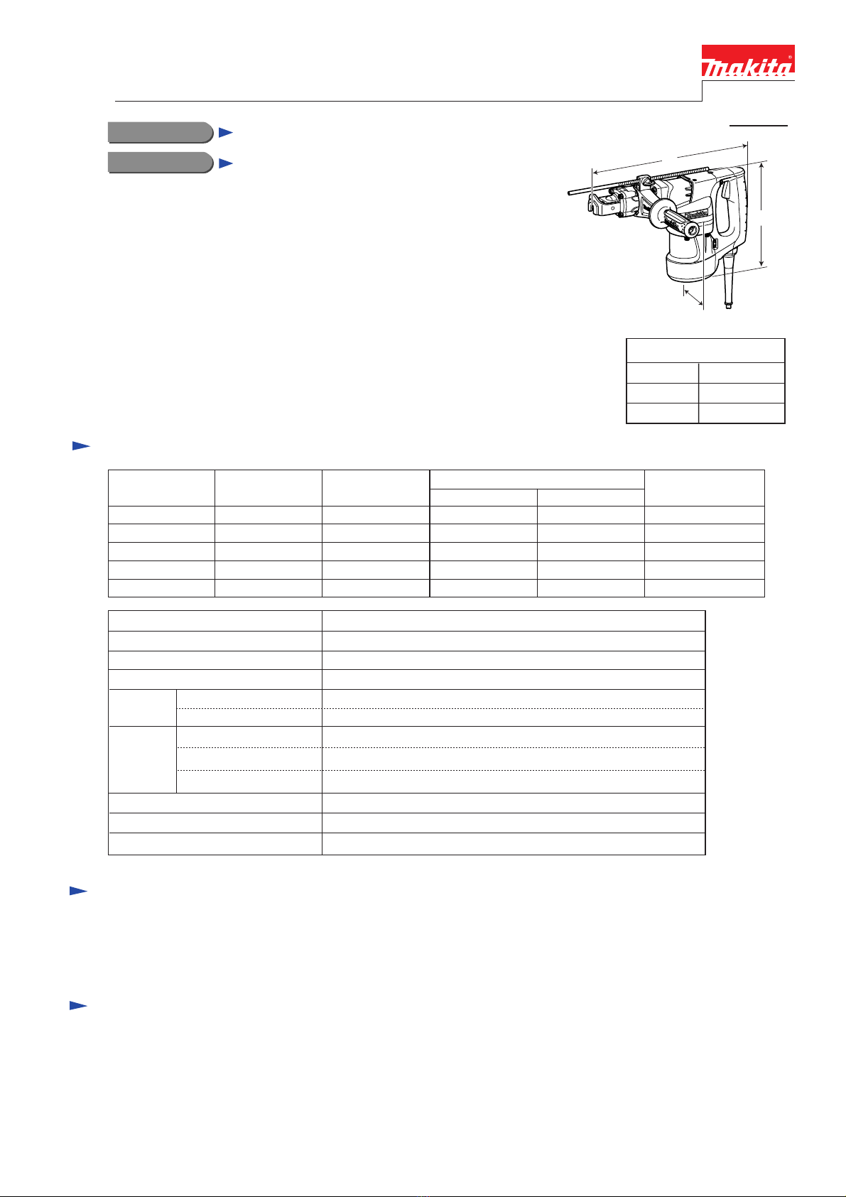
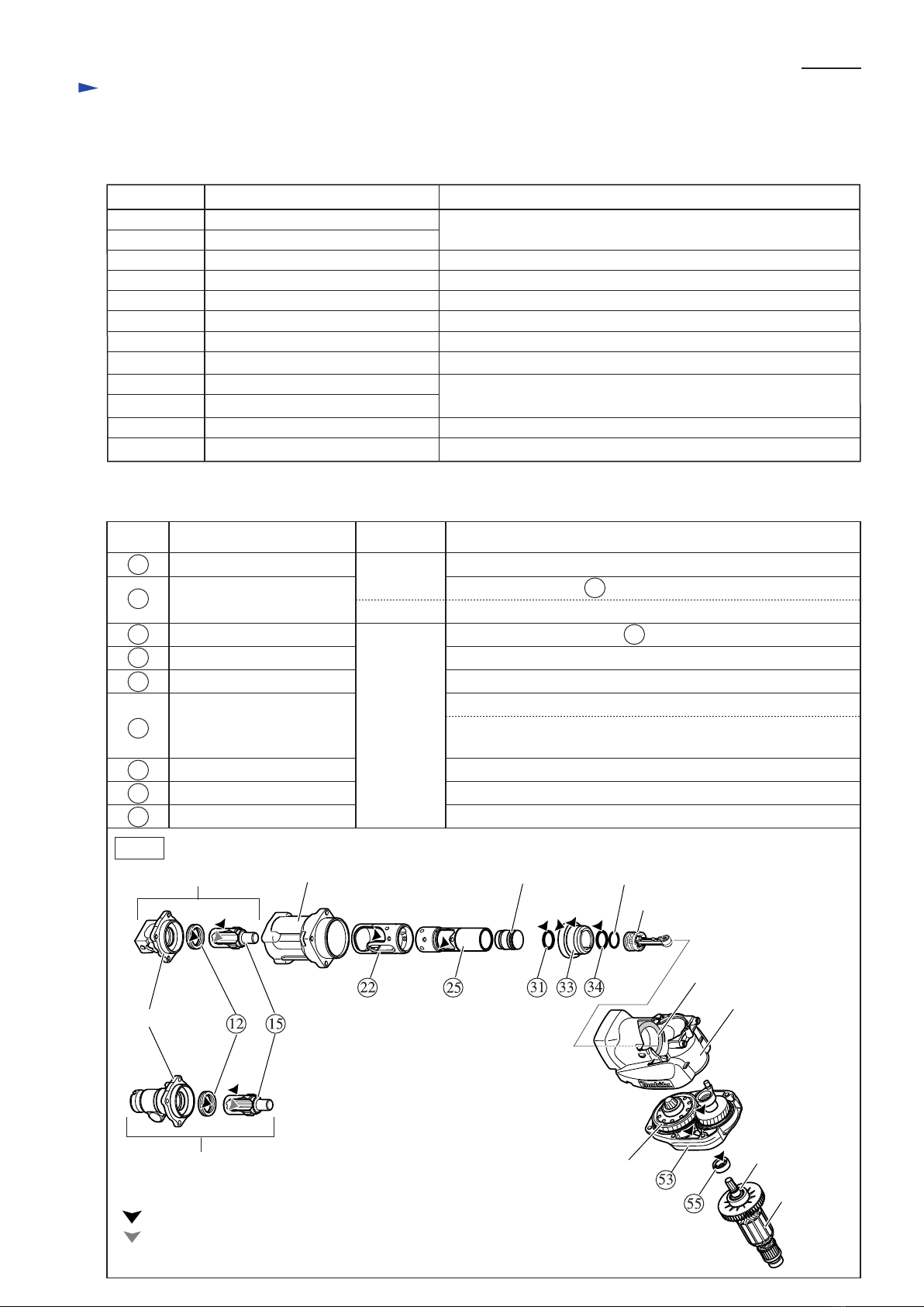
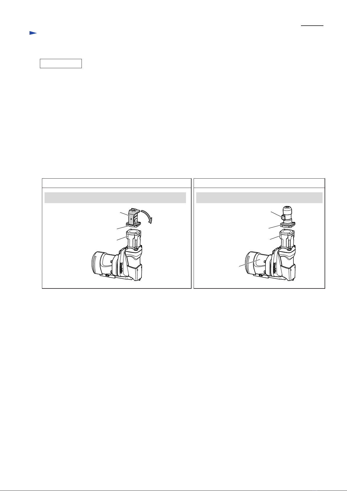
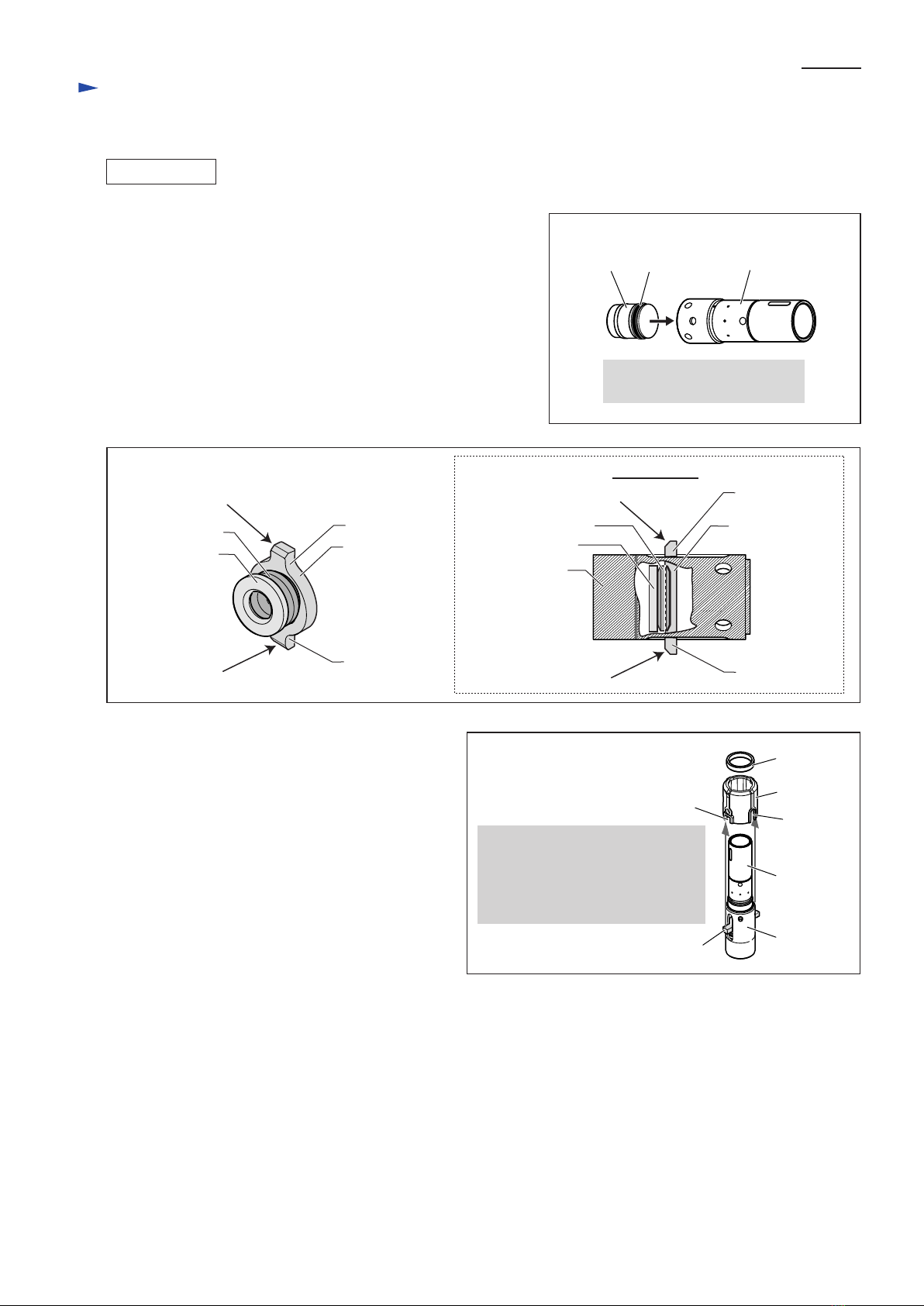
Makita HR4030C Manual

Model No.
Description
PRODUCT
CONCEPT AND MAIN APPLICATIONS
Specification
Standard equipment
Note: The standard equipment for the tool shown may differ from country to country.
P 1 /13
Dimensions: mm (")
Width (W)
Height (H)
Length (L) 413 (16-1/4)
107 (4-1/4)
247 (9-3/4)
Shank type: mm (")
Yes (by dial)
Europe: 4.0 (13.1), Brazil: 2.0 (6.6), other countries: 5.0 (16.4)
Yes
230 - 460
1,300 - 2,600
17 (11/16) Hex
1,100
6.2 (13.7)
Impacts per minute: min -1= ipm
No load speed: min -1= rpm
HR4030C
Rotary Hammer 40mm (1-9/16")
Model HR4030C 40mm Hex Rotary Hammer has been developed
as the successor model of HR3850 and HR3811 to compete with
Model H1 and H2 of the competitor H.
Ensures work efficiency higher than the competing models,
but still featuring lightweight, slim and compact tool design.
Continuous rating input: W
Double insulation
Net weight: kg (lbs)
Plastic carrying case .........1 pc
Depth gauge ................... 1 pc
Side handle ...................... 1 pc
Power supply cord: m (ft)
Variable speed control
Yes
YesConstant speed control
40 (1-9/16)Max TCT bit diameter
118 (4-5/8)Max Core bit diameter
Capacity:
mm (")
Optional accessories
TCT bits (hex shank),TCT bits (straight shank), Bull points, TCT bits (taper shank), Cold chisels, Taper shank adapter,
Scaling chisels, Cotter, Core bits, Grooving chisels, Clay spade, Center bit, Rammer, Core bit adapter,
Bushing tool, Chemical anchor adapter, Shank (for Rammer and Bushing tool),
Blow-out bulb, Ground rod adapter, Hammer service kit, Hammer grease, Bit grease
W
L
H
TECHNICAL INFORMATION
Continuous Rating (W)
Voltage (V) Cycle (Hz) Input Output Max. Output (W)
110
120
220
230
240
12.0
11.0
6.2
6.2
6.2
50/ 60
50/ 60
50/ 60
50/ 60
50/ 60
1,100
---
1,100
1,100
1,100
500
500
550
550
550
1,200
1,200
1,500
1,500
1,500
Current (A)
Electronic
features Soft start

P 2 /13
[2] LUBRICATION
Apply the following grease to the portions designated with the triangles to protect parts and product from unusual abrasion.
[1] NECESSARY REPAIRING TOOLS
CAUTION: Disconnect the machine, and remove the hammer bit for safety
before repair/ maintenance, in accordance with the instruction manual!
Repair
Fig. 1
Tool holder
Striker O ring 21
Plane bearing
(factory-assembled part)
Piston
Crank housing
complete
Armature
Sleeve 12
Barrel complete
Model 4041C
Model 4030C
12 X Ring 28 Lip portion
Lip portion
Inside surface that contacts 15 Impact bolt
5g to the inside surface that contacts Striker and Piston
1-2g to the hole where hammer bit is inserted
Surface that contacts 12 X ring 28
Impact bolt
Cylinder A
Cylinder B
O Ring 22 Whole surface
Whole surface
30g each to Gear portion and Crank portion
O ring 22
Oil seal 15
Gear housing complete
Spiral bevel gear 27
Teeth portion that engages with Torque limiter
Cylindrical portion that contacts Plane bearing of
Crank housing complete
22
25
31
33
34
53
55
15
Torque limiter
1R045 Gear extractor (large) Removing Armature
1R269 Bearing extractor Removing Helical gear 38
1R346 Center attachment for 1R045
1R228 1/4" Hex shank bit for M4 Removing/fastening M4 size Hex socket head bolts
1R291 Retaining ring S and R pliers Removing/installing Retaining ring S-20
1R311 Retaining ring pliers Removing/installing Ring spring 32
1R230 1/4" Hex shank bit for M6 Removing/fastening M6 size Hex socket head bolts
1R288 Screwdriver magnetizer Magnetizing tools for removing small steel parts
1R239 Round bar for arbor 10-100 Removing Crank shaft from Crank housing complete
1R350 Ring 60 Supporting Crank housing complete when removing Crank shaft
--- Hex wrench 5 Removing Tool holder from Barrel complete, and Barrel complete
from Crank housing complete--- Steel pipe
DescriptionCode No. Use for
Item No. Description Portion to lubricateGrease type
R.No.00
R.No.00
N.No.2
:Makita grease R.No.00
:Makita grease N.No.2 (= Makita bit grease)

P 3 /13
[3] DISASSEMBLY/ASSEMBLY
[3] -1. Tool Retainer
Repair
Cut-off wheel
Model 4030C
Assemble Tool retainer to Tool holder using arbor press as illustrated in Fig. 3.
Model 4041C
1) Mount Tool retainer on Tool holder. (Fig. 2A)
2) Fasten M8x12 Hex bolt securely to Tool retainer through Compression spring 5. (Fig. 2A)
Note: Be sure to apply threadlocker to the threaded portion of M8x12 Hex bolt.
The recommended threadlocker is Loctite 603 or Threebond 1303B.
3) Assemble Cap to Tool holder while fitting the two projections on Cap in the notch of Tool holder. (Fig. 3A)
Angle grinder
Tool retainer
Tool holder
center line of
the two holes
Tool holder Tool holder
work bench
Tool retainer
Fig. 2 Fig. 2A
Model 4030C
Damaged Tool retainer can be disassembled from Tool holder by cutting it into two using Angle grinder or the like
as illustrated in Fig. 2.
Model 4041C
1) Remove Cap from Tool holder by hand. (Fig. 2A)
2) By unscrewing M8x12 Hex bolt, Tool retainer and Compression spring 15 can be disassembled from Tool holder.
(Fig. 2A)
Note: Threadlocker is applied to the thread portion of M8x12 Hex bolt.
Tool retainer
Hex bolt M8x12
Compression spring 15
Cap Tool holder
projection
notch
Cap
ASSEMBLING
DISASSEMBLING
HR4030C HR4041C
Fig. 3 Fig. 3A
HR4030C HR4041C
arbor press
Be sure to place the side nearer
to the centerline of the two holes
on work bench.

P 4 /13
[3] DISASSEMBLY/ASSEMBLY
[3] -2. Handle Section, Tool Holder, Barrel Complete, Piston, Connecting Rod
Repair
1) Remove two M6x20 Hex socket head bolts and two 5x25 Tapping screws, and disconnect Lead unit from Controller.
Handle section can now be removed. (Fig. 4)
2) Put the machine on work bench as illustrated in Fig. 5, and disassemble Tool holder from Barrel complete by removing
four M6x25 Hex socket head bolts with Impact driver and 1R230. (Note: The tool image in Fig. 5 is Model HR4030C.)
Important: Be sure to loosen four M6x25 Hex socket head bolts a little using Hex wrench 5 and steel pipe before
unscrewing them with Impact driver and 1R230. Using Impact driver and 1R230 from the start will
result in breakage of 1R230.
The following four parts can now be taken out from Barrel complete: Nylon washer 29, Flat washer 29, Impact bolt,
O ring 48. (Fig. 5) X ring 28 can be removed from Tool holder using small slotted screwdriver. (Fig. 5A)
3) Disassemble Barrel complete from Crank housing complete by unscrewing four M6x30 Hex socket head bolts in the
same way as described above in the step 2), then pull out Cylinder section from Crank housing complete. (Fig. 6)
4) Disconnect Connecting rod from Crank shaft in Crank housing complete, then take out Connecting rod and Piston
from Crank housing complete. O ring 22 can now be replaced. (Fig. 7)
Hex socket head
bolt M6x25 (4 pcs)
Tool holder
X ring 28
Nylon washer 29
Impact driver
1R230
Flat washer 29
Impact bolt
Barrel complete
Barrel complete
Cylinder section
Key 4 (2 pcs)
O ring 48
Crank housing
complete
Crank housing complete
O ring 22
Piston
Connecting rod
Fig. 4 Fig. 5
Fig. 6
Fig. 7
DISASSEMBLING
Handle section
Flat washer 6 (2 pcs)
Hex socket head
bolt M6x20 (2 pcs)
Tapping screw 5x25
(2 pcs)
Lead unit
Controller
Hex wrench 5
*Attach an appropriate
steel pipe as extension
bar.
*steel pipe
Remove four M6x25
Hex socket head bolts by:
first loosening a little
using Hex wrench 5
and steel pipe,
then unscrewing with
Impact driver and
1R230.
Fig. 5A
Tool holder
Impact driver
1R230
Hex wrench 5
*Attach an appropriate
steel pipe as extension
bar.
*steel pipe
Remove four M6x30
Hex socket head bolts by:
first loosening a little
using Hex wrench 5
and steel pipe,
then unscrewing with
Impact driver and
1R230.
Hex socket head
bolt M6x30 (4 pcs)

P 5 /13
[3] DISASSEMBLY/ASSEMBLY
[3] -2. Handle Section, Tool Holder, Barrel Complete, Piston, Connecting Rod (cont.)
Repair
1) Assemble O ring 22 to Piston, then connect Connecting rod with Crank shaft in Crank housing complete.
(Fig. 7 in page 4)
2) Put Cylinder section into Crank housing complete, and insert Piston into Cylinder section.
Align each Key 4 on Cylinder section with the corresponding groove on the inside surface of Spiral bevel gear 27,
then insert Cylinder section into Spiral bevel gear 27 until it stops. (Fig. 6 in page 4)
3) Do the reverse of 2) and 1) of the disassembling steps. (Figs. 5, 4 in page 4)
Note:
1. Tool holder is not reversible when assembled to Barrel complete.
Be sure to assemble as illustrated in Figs. 8, 8A.
2. Do not forget to place O ring 48 between Tool holder and Barrel complete.
3. Do not confuse M6x30 Hex socket bolts that fasten Barrel complete to Crank housing with M6x25 that fasten
Tool holder to Barrel complete.
4. Be careful not to twist X ring 28 when assembling it to Tool holder. Lubricate the lip portion of X ring 28
with reference to [2] Lubrication in page 2 when Impact bolt is inserted.
ASSEMBLING
Tool retainer must swivel in the direction of the gray arrow. Tool retainer must be placed on Motor housing side.
Tool holder
Barrel complete
Tool retainer
HR4030C HR4041C
Fig. 8AFig. 8
Barrel complete
Tool holder
Tool retainer
Motor housing

P 6 /13
[3] DISASSEMBLY/ASSEMBLY
[3] -3. Cylinder Section
Repair
1) Remove Tool holder and Barrel complete from the machine, and take out Cylinder section from Crank housing complete.
(Figs. 4, 5, 6 in page 4)
2) Disassemble Cylinder B from Cylinder section as illustrated in Fig. 9 to Fig. 14.
Note: When removing Pin 6, it is recommended to use a screwdriver magnetized with 1R288 in advance.
Fig. 10
Fig. 13 Fig. 14
Flat washer 34
Pin 6 (4 pcs)
Cylinder BCylinder A
Put Cylinder section
on work bench with
Cylinder B side up.
Then remove Ring
spring 32 using 1R311
while pressing down
Flat washer 34.
Disassemble Cylinder B from Cylinder A
by removing Pin 6 (4 pcs).
Push out Striker from Cylinder B.
Remove O ring 22 from Striker.
Ring spring 32
Cylinder B
1R311
Fig. 11
Remove Flat washer 34 and
Compression spring 35.
Flat washer 34
Compression
spring 35
Fig. 12
Ring 34
Slide sleeve
Fig. 9
Cylinder section
Key 4 (2 pcs)
Remove Key 4 (2 pcs) from
Cylinder B using pliers.
Cylinder B
Cylinder A
DISASSEMBLING
Remove Ring 34 and Slide sleeve.
O ring 22Striker

P 7 /13
Repair
Slide plateRubber ring 18Washer 17
Cylinder A
(viewed from X)
The structure of Cylinder A
Removing Rubber Ring 18
Removing Slide Plate
Removing Washer 17
Cylinder A
Fig. 15
Fig. 17 Fig. 18
Fig. 19
Fig. 16
First, slide Slide plate in the direction of the arrow
until it stops to make a space for removing
Rubber ring 18, Flat washer 17 and Slide plate itself.
Turn Rubber ring 18 so that
it can be seen through the
elliptic hole of Cylinder A
as illustrated below.
Washer 17 can be removed in the same way
as you did in Removing Rubber Ring 18.
Now can be removed
through the hole.
Rubber ring 18 Rubber ring 18
Tilt Slide plate in the direction of
the arrow until it stops.
Slide plate
4) Disassemble Cylinder A as illustrated in Fig. 15 to Fig. 19.
[3] DISASSEMBLY/ASSEMBLY
[3] -3. Cylinder Section (cont.)
DISASSEMBLING
X
Slide plate
Washer 17Washer 17
Slide plate can now be removed in the same way
as you did in Removing Rubber Ring 18.

P 8/13
[3] DISASSEMBLY/ASSEMBLY
[3] -3. Cylinder Section
Repair
1) Assemble O ring 22 to Striker, then insert Striker into Cylinder B
as illustrated in Fig. 20.
2) Assemble Slide plate, Rubber ring 18 and Washer 17 to Cylinder A
by doing the reverse of the disassembling step 4) in page 7.
(Figs. 19 to 15)
Note: Slide plate is not reversible when assembled to Cylinder A.
The beveled side of the two protrusions of Slide plate must
face towards Tool holder side as illustrated in Fig. 21.
3) Assemble Cylinder B to Cylinder A. (Fig. 13 in page 6)
4) Assemble Slide sleeve and Ring 34 to the assembly
of Cylinder A and Cylinder B. (Fig. 22)
5) Do the reverse of the disassembling steps.
(Figs. 11 to 4 in pages 4, 5, 6)
Fig. 21
Cylinder A
Rubber ring 18 Slide plate
Washer 17
ASSEMBLING
[Tool holder side]
[Cylinder B side]
[Tool holder side]
[Cylinder B side]
Fig. 20
O Ring 22
O ring 22 must be placed on
Crank housing complete side.
Cylinder BStriker
[Cylinder A side]
[Crank housing complete side]
Cross section
Rubber ring 18
Washer 17 Slide plate
beveled side
beveled side
beveled side beveled side
protrusion
protrusion
protrusion
protrusion
Ring 34
Note:
Be sure to fit the two protrusions
of Slide plate in the corresponding
small notches, not large ones,
of Slide sleeve.
protrusion of Slide plate
small notch
Fig. 22
Slide sleeve
Cylinder A
Cylinder B
large notch

P 9/13
[3] DISASSEMBLY/ASSEMBLY
[3] -4. Armature, Crank Section
Repair
Hex socket head bolt
M6x60 (4 pcs)
Hex socket head bolt
M6x20 (2 pcs)
1R045
1R346
Flat washer 6
(4 pcs)
Crank housing
complete
Crank housing
complete
Gear housing
complete
Gear housing
complete
Motor housing
Armature
1) Remove the following parts and sections from the machine (Fig. 4 to Fig. 7 in page 4):
Handle section, Tool holder, Barrel complete, Piston, Connecting rod
2) Remove Rear cover, then disconnect Carbon brushes from Armature commutator as illustrated in Fig. 23.
Note: No need to take out Carbon brush from Brush holder.
3) Remove Motor housing from Gear housing complete by unscrewing four M6x60 Hex socket head bolts. (Fig. 24)
4) Remove Crank housing complete from Gear housing complete. (Fig. 25)
Note: Crank section (including Crank shaft, Helical gear 38, etc) still remain in Crank housing complete in this step.
See page 10 for disassembling of Crank section.
5) Torque limiter assembly can be disassembled from Gear housing complete by tapping the end surface of
Gear housing complete with plastic hammer. (Fig. 26)
Important: Do not try to disassemble Torque limiter assembly because it cannot be reassembled once disassembled.
6) Armature can now be disassembled from Gear housing complete using 1R045 and 1R346. (Fig. 27)
Fig. 23 Fig. 24
Fig. 25 Fig. 26 Fig. 27
Torque limiter assembly
DISASSEMBLING
Rear cover
Tapping screw 4x18
(2 pcs)
Remove the end of Spiral spring from Carbon
brush using small slotted screwdriver or the like,
then pull Carbon brush a little to disconnect
from Armature commutator.
Disconnecting Carbon brush
from Armature commutator
Spiral spring of Brush holder is pushing in
Carbon brush to contact Armature commutator.
Carbon brush
Spiral spring
of Brush holder

P 10/13
[3] DISASSEMBLY/ASSEMBLY
[3] -4. Armature, Crank Section (cont.)
Repair
Fig. 31
Crank cap cover
Hex socket head bolt
M4x14 (3 pcs)
Crank cap
Flat washer 4 (3pcs)
Crank housing
complete
Fig. 28
1R269
Helical gear 38
Crank shaft
Retaining ring S-20
Ball bearing 6004LLU
1R291
7) Remove Crank cap cover and Crank cap by unscrewing three M4x14 Hex socket head bolts using 1R228 and
Impact driver. (Fig. 28) Crank section can now be seen in Crank housing complete. (Fig. 29)
8) Align Crank pin of Crank shaft with the notch in Crank housing complete as illustrated to right in Fig. 29.
9) Put Crank housing complete on 1R350, and apply 1R239 to the bottom center of Crank shaft.
Then disassemble Crank section from Crank housing complete by pressing down 1R239 using arbor press. (Fig. 30)
10) Crank section can be disassembled using 1R269 and 1R291 as illustrated in Fig. 31.
Crank housing complete,
viewed from Crank cap cover side
Fig. 29
Crank housing complete
Fig. 30
1R239
1R350
Crank shaft
Crank section
Flat washer 10
DISASSEMBLING
Crank pin of
Crank shaft
notch in Crank
housing complete
Disassembling Crank Section
Do the reverse of the disassembling steps.
Note:
Do not forget to mount O ring 50 and Filter on Crank cap. (Fig. 32)
ASSEMBLING
Crank cap
Filter
O ring 50
Fig. 32
Crank housing
complete

P 11/13
[3] DISASSEMBLY/ASSEMBLY
[3] -5. Replacing Electrical Parts in Handle Complete
Repair
Remove handle cover from Handle complete
by unscrewing one 4x18 Tapping screw. (Fig. 33)
The following electrical parts can now be replaced:
Switch, Power supply cord, Cord guard.
Tapping screw
4x18 (1 pc)
Strain relief
Handle cover
Handle complete
Switch
Fig. 33
Tapping screw
4x18 (1 pc)
Power supply cord
Cord guard

P 12 /13
[3] DISASSEMBLY/ASSEMBLY
[3] -6. Recommended Fastening Torque for Hex Socket Head Bolts
[4] PERIODICAL MAINTENANCE
Repair
M6x25 Fastening Tool holder to Barrel complete
Fastening Crank cap cover to Crank housing complete
Fastening Handle complete to Crank housing complete
Fastening Gear housing complete to Crank housing complete
Fastening Motor housing through Gear housing complete
to Crank housing complete
Fastening Barrel complete to Crank housing complete
Tool holder
Crank cap cover
Barrel complete
Crank housing complete
Gear housing complete
Motor housing
Flat washer 6 (4 pcs)
Flat washer 6 (2 pcs)
Flat washer 4 (3 pc)
Handle complete
8
Item No. Size
4
Q' ty Used for
7.8 - 12.0
7.8 - 12.0
7.8 - 12.0
7.8 - 12.0
3.9 - 5.9
2.9 - 4.9
Fastening
Torque: N.m
M6x3020 4
M6x2054 2
M6x2084 2
M6x6068 4
M4x1439 3
When replacing Carbon brushes normally worn out, it is recommended to;
1) Replace the four parts designated in Fig. 35 with new ones.
2) Completely remove old grease from Crank room (= the space between Crank housing complete and Gear housing
complete) and apply new lubricants to the parts designated in [2] LUBRICATION on page 2.
X ring 28
O ring 22
O ring 22
Oil Seal 15
Piston
Gear housing complete
Striker
Tool holder
Item No. Description
Fig. 34
Fig. 35

Circuit diagram
Wiring diagram
P 13/13
Field
Brush holder unit
Power supply cord
Switch
Handle section
Motor housing
Lead unit
Controller
Color index of lead wires' sheath
Black
White
Fig. 36
Fig. 37
Lead unit
Switch
Sponge sheet
Lead wire of Lead unit (white)
Lead wires must be tight
between Switch and Sponge sheet.
Lead wire of Lead unit (black)
Protective tube
Handle complete,
viewed from rear side
23
45
Route two Lead wires of Lead unit
from Motor housing side through
this opening.
Fix two Lead wires of Lead unit
with this groove of Sponge sheet.
Fix two Lead wires of
Power supply cord with
this groove of Sponge sheet.
Lead wire of Power supply cord
Other manuals for HR4030C
2
Table of contents
Other Makita Rotary Hammer manuals

Makita
Makita M8700G User manual

Makita
Makita HR2450 Series User manual

Makita
Makita HR006GD203 User manual

Makita
Makita BHR200 User manual

Makita
Makita HR4001C User manual

Makita
Makita XRH07 User manual

Makita
Makita HR166DZJ User manual

Makita
Makita HR1830 User manual

Makita
Makita HR4001C Manual

Makita
Makita HR4500C User manual

Makita
Makita HR4040C Manual

Makita
Makita HR4003C User manual

Makita
Makita HR3851 User manual

Makita
Makita HR4510C User manual

Makita
Makita HR4501C User manual

Makita
Makita HR5001C User manual

Makita
Makita HR4003C User manual

Makita
Makita HR4003C User manual

Makita
Makita HR2800 User manual

Makita
Makita DHR171RAJ User manual